

Page 1
I. PREPARING FOR INSTALLATION:
1. Review installation drawings and wiring diagram to familiarize yourself with the use
and wiring of the system.
NOTE: These instnx:tions apply to both the 2-Door and 4-Door Lock systems.
If installing the 2-Door system, ignore the section applicabie to the 4-Door system.
2. Determine where the CONTROL MODULE will be mounted. This will normally be
behind the dash near the fuse block to allow for connection of the 12 Volt Positive
and Ground Wires.
3. Examine the WIRING HARNESS. You will find two groups of 5 wires each (on 4-door
models you will also find two groups of 2 wires each). One of the 5-wire harnesses
will be shorter than the other. This short harness is to be routed to the front door
nearest the mounting location of the CONTROL MODULE.
4. Remove door panels on all doors.
II. CONTROL MODULE MOUNTING & WIRE ROUTING:
1. Select mounting location for CONTROL MODULE and secure with two self-tap 4 X
12 mm screws.
2. Plug wiring harness into control module.
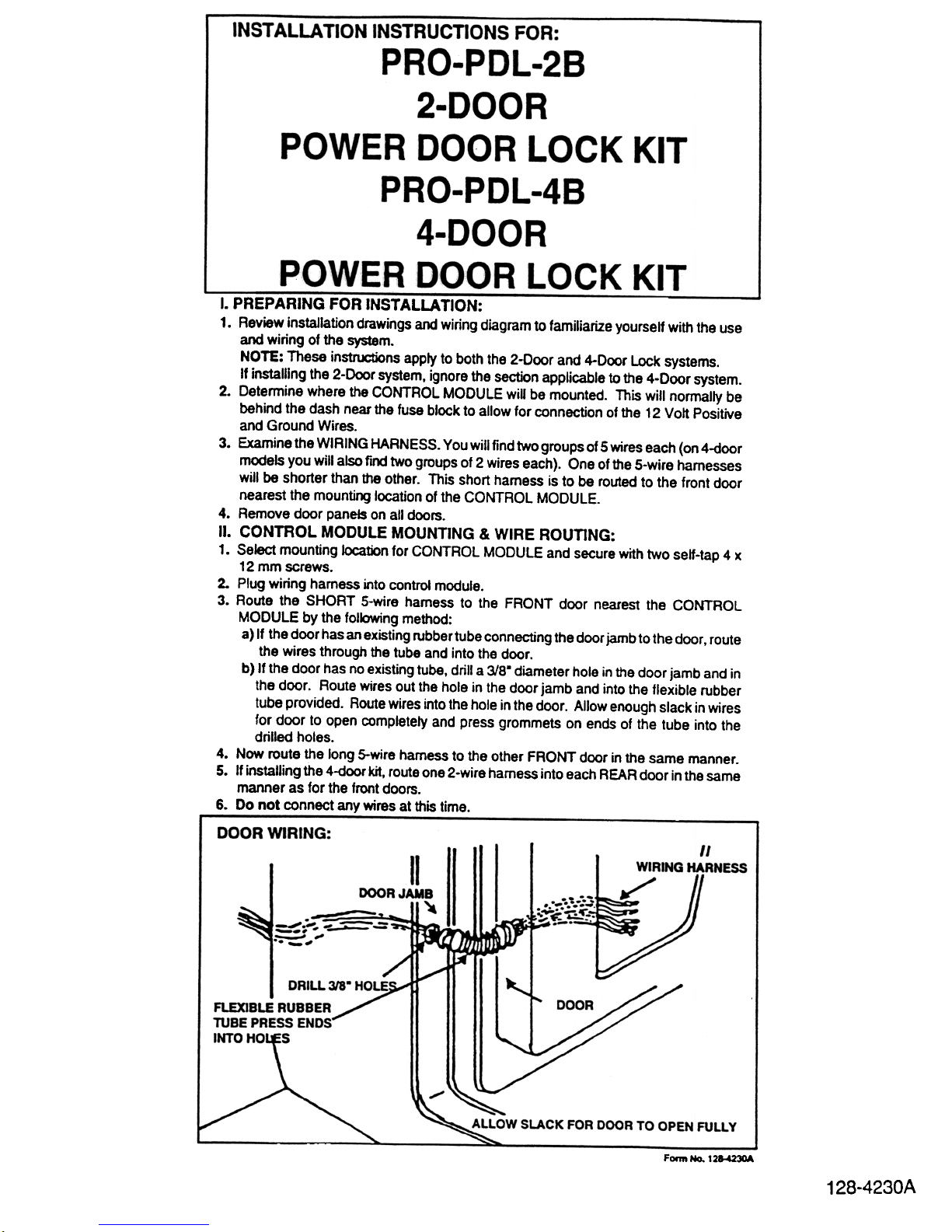
3. Route the SHORT 5-wire harness to the FRONT door nearest the CONTROL
MODULE by the folk)wing method:
a) If the door has an existing rubber tube connecting the door jamb to the door. route
the wires through the tube and into the door.
b) If the door has no existing tube, drill a 3/8. diameter hole in the door jamb and in
the door. Route wires out the hole in the door jamb and into the flexible rubber
tube provided. Route wires into the hole in the door. Allow enough slack in wires
for door to open completely and press grommets on ends of the tube into the
drilled holes.
4. Now route the long S-wire harness to the other FRONT door in the sarne manner.
5. If installing the 4-door kit, route one 2-wire harness into each REAR door in the same
manner as for the front doors.
6. Do not connect any wires at this time.
Form No. 12&-42~
128-4230A
Page 2
III. POWER LOCK MECHANISM MOUNTING:
1. Refer to mounting illustration for POWER LOCK MECHANISM.
2. Select mounting location insKje door that will not interfere with WINDOW.
WINDOW MOVEMENT, DOOR MECHANISM or any other part within the door.
3. Make certain thls location will enable connection of the POWER LOCK
MECHANISM to the existing door lock button mechanism as shown.
4. Once selected, use one of the two possible mounting methods shown (direct
mounting to door frame method or use of mounting support strap method).
5. Once the mounting method Is decided on, install the POWER LOCK MECHANISMS in each door using the hardware shown in the applicable drawing.
NOTE: Use 5-wire locks in front doors and 2-wire locks in rear doors.
IV. CONNECTION OF POWER DOOR LOCK MECHANISM TO DOOR
LOCK:
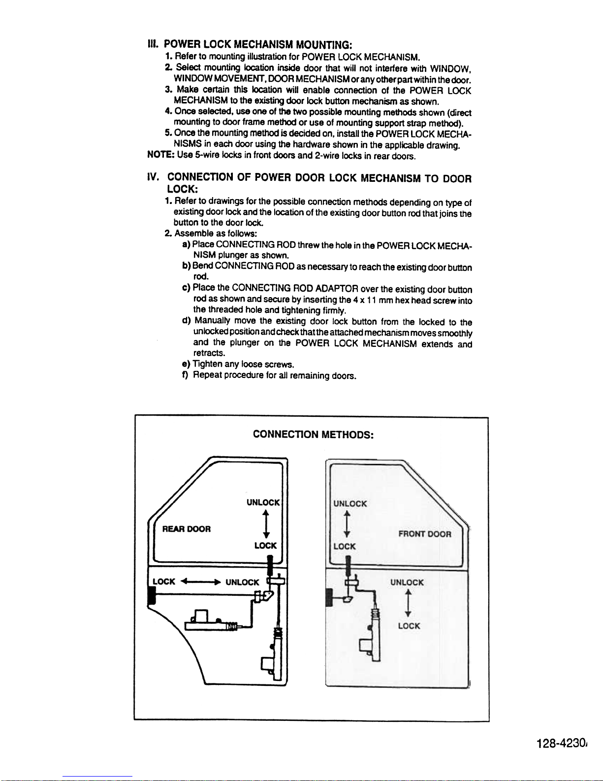
1. Refer to drawings for the possible connection methods depending on type of
existing door lock and the location of the existing door button rod that joins the
button to the door lock.
2. Assemble as follows:
a) Place CONNECTING ROD threw the hole in the POWER LOCK MECHA-
NISM plunger as shown.
b) Bend CONNECTING ROD as necessary to reach the existing door button
rod.
c) Place the CONNECTING ROD ADAPTOR over the existing door button
rod as shown and secure by inserting the 4 x 11 mm hex head screw into
the threaded hole and tightening firmly .
d) Manually move the existing door lock button tram the locked to the
unlocked position and check that the attached mechanism moves smoothly
and the plunger on the POWER LOCK MECHANISM extends and
retracts.
e) Tighten any loose screws.
f) Repeat procedure tor all remaining doors.
CONNECTION METHODS:
UNLOCK I I
REAR DOOR
LOCK
Ji
LOCK ~ ~ UNLOCK
~
I
c
128-4230J
Page 3

Page 4

v. WIRING:
1. Plug the fIVe wires in each front door into the matching color wires on the POWER
LOCK MECHANISMS.
2. Plug the two wires in each rear door into the matching color wires on the POWER
LOCK MECHANISMS.
3. Secure the BLACK wire on the CONTROL MODULE to a grounded metal part of
the vehIcle.
4. Splice the RED FUSEDWIRE on the CONTROL MODULE to a CONSTANT -ON
(always live) +12 volt battery source at the fuseblock that is rated for at least 20
amps.
VI. TESTING:
1. Close all doors except the driver's door. Check that all doors are unlocked.
2. Close the driver's door and lock it using the door lock key. All doors must lock
automatically at the same time.
3. Now unlock the driver's door using the key and check that all doors unlock at the
same time.
4. Now push the drivers door lock button down and check that all door buttons go
down.
5. Repeat steps 1.2 and 3 using the passenger's door.
NOTE: On the 4-door lock systems, only the two front doors control the system.
(Locking the rear doors will not lock the front doors but locking either front door will
lock all other doors).
6. Once the system is tested, replace the door panels and re-test the system.
VII. REVERSE WIRING FOR 2 DOORS & 4 DOORS
NOTE: When the power door locking mechanisms are wired as shown in the
manual, the plunger will extend when the door signals "UNLOCK" and will retract
when the door signals "LOCK".
In some installations it may be necessary to mount the plunger mechanism in such
a position that reversed actuation is required (see reversed wiring).
REVERSED WIRING
In order to make the plunger retract when the door signals "UNLOCK" and extend
when it signals "LOCK", reverse the wiring as follows:
1. For rear doors, reverse the "BLUE" and "GREEN" wires.
2. For front doors, reverse the "BLUE" with the .GREEN" wires: reverse the
"BROWN" with the .WHITE" wires. Connect "RED" in all cases.
NOTE: You do not have to reverse wire all the plungers, only one can be reversed
wired if desired.
VIII. REMOTE CONTROL INPUTS
a) Positive Trigger: Red/8lack twin lead
Black Wire: + Lock Input
Red Wire: + Unlock Input
b) Negative Trigger: Red/Green twin lead
Red Wire: -lock Input
Green Wire: -Unlock Input
Audiovox GOrp. 150 Marcus Blvd., Hauppauge, N. y .11788
Printed in Taiwan Form No. 128-4230A
1?R-J1?~nd
Page 5

STOP BLOCK ADJUST DET AIL:
I
I
I
~ ~ Q : , ,
.
CONNECTING ROD ADAPTOR 1
I ~
DOOR LOCK ROD --'
(EXIST1NG)
':
TO LOCKING MECHANISM
128-4230A
Page 6

 Loading...