

Page 1
Model :PRO-OE3
TRANSMITTER PROGRAMMING GUIDE
The transmitters included with the security system have been
pre-pro
specific function of the security system. Although the security system in the
vehicle has eithera3or4channel receiver, depending on the model, the
transmitters included with the system are capable of transmitting 7 distinct
signals. This allows you to program each transmitter to more than one vehicle
in two car families, and also allows you to change which button(s) control
certain functions of the system.
( Example: Transmitter channel 5 can be programmed to activate Receiver
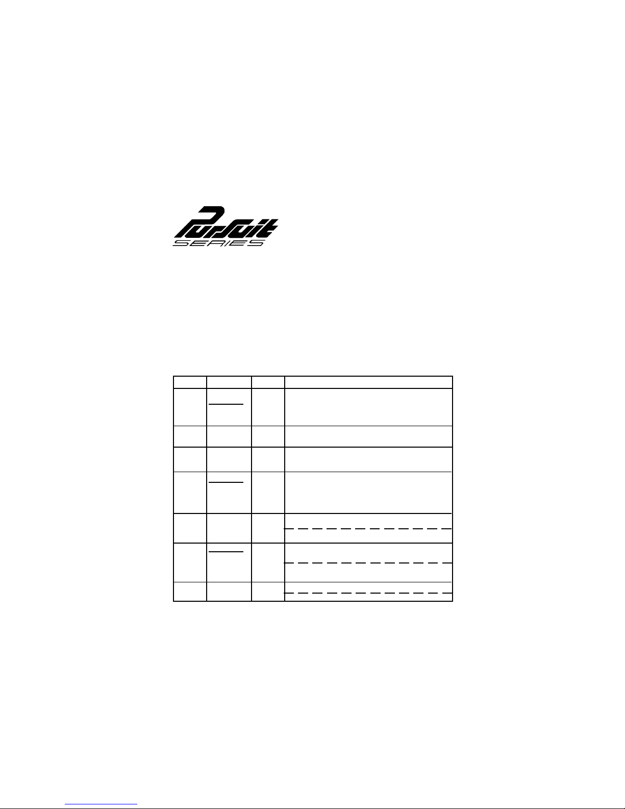
channel 2.) Refer to the chart below for access to each of the transmitter
channels, and for the standard factory button assignments.
TRANSMITTER SYSTEM RECEIVER
CHANNEL BUTTONS CHANNEL FUNCTION
grammed at the factory, with each button pre-assigned to control a
1 ARM 1 **Remote Arm & Disarm
DISARM **Remote Emergency Panic
Remote Door Lock & Unlock
2 OPTION 1 2 * Pulsed Output for Accessories
3 OPTION 2 3 * Switched Output for Accessories
ARM 4 * Switched Output for Accessories
DISARM
4&
OPTION 1
OPTION 1
5&
OPTION 2
ARM
DISARM
6&
OPTION 2
7 ALL 3
BUTTONS
Page 2

Some of the more common accessories for these additional channels
are;
In addition to the information provided above, the PRO-OE3 transmitter is
capable of utilizing different transmitter Icon pads. These replacement pads
may be used with your transmitter, depending on the specific options that
may have been installed or added to your security/keyless entry system.
(If your transmitter appears more like one of the units shown on page 4 of
this manual, use the text reference along side the specific transmitter for
programming your unit).
PROGRAMMINGTHETRANSMITTERS
It is important to remember that during programming, each individual step of
the procedure must be executed within 15 seconds of the previous step.
When the 15 second time limit is allowed to expire, the system will
automatically terminate the programming mode. This is indicated by a long
chirp from the siren.
Additionally, the system will store codes from up to four different
transmitters. If a 5th transmitter is programmed to any receiver channel,
then the first transmitter programmed to that channel will be erased from
the system's memory.
Non alarm models will flash the parking lights only to confirm the transmitter
code has been learned and stored.
Transmitter PD 10 is referenced during the program procedure listed below.
To Program replacement or additional transmitters:
1. Enter the vehicle, and turn the ignition key to the " on " position.
2. Flip the valet switch "on" - "off" - "on" - "off" - "on" - then "off".
3. The dash L.E.D. will flash one time, and the sounding device will beep
4. Press and hold the Arm/Disarm button for 4 seconds or until the sounding
5. If you have additional transmitters ( up to 4 ) that need to be programmed,
6. Flip the valet switch "on" then "off".
7. The dash L.E.D. will flash two times, and the sounding device will beep
8. Press and hold the Option 1 or Option 2 transmitter button(s)for4
*AS 9554 Remote Garage Door Interface
*AS 9075 Remote car starter
*AS 9153 Remote window roll up
*AS 9256 Remote trunk release relay
** Only Available With Remote Alarm Systems
one time, indicating the system is ready to accept programming for
receiver channel 1.
device emits a long beep, indicating the signal has been stored into
memory.
repeat step 4 for each transmitter.
two times, indicating the system is ready to accept programming for
receiver channel 2.
seconds or until the sounding device emits a long beep, indicating the
signal has been stored into memory.
2
Page 3

9. If you have additional transmitters ( up to 4 ) that need to be programmed,
repeat step 8 for each transmitter.
10. Flip the valet switch "on" then "off".
11. The dash L.E.D. will flash three times, and the sounding device will beep
three times, indicating the system is ready to accept programming for
receiver channel 3.
12. Press and hold the selected Option 1 or Option 2 transmitter button(s)for
4 seconds or until the sounding device emits a long beep, indicating the
signal has been stored into memory.
13. If you have additional transmitters ( up to 4 ) that need to be programmed,
repeat step 12 for each transmitter.
14. Flip the valet switch on then off.
15. The dash L.E.D. will flash four times, and the sounding device will beep four
times, indicating the system is ready to accept programming for receiver
channel 4.
16. Press and hold the remaining Option 1 or Option 2 transmitter button(s)
for 4 seconds or until the sounding device emits a long beep, indicating the
signal has been stored into memory.
17. If you have additional transmitters ( up to 4 ) that need to be programmed,
repeat step 16 for each transmitter.
18. Turn the ignition key off. The sounding device will emit one short beep
followed by one long beep indicating the system has terminated the program
mode.
You will notice a decrease in transmitter range as the battery condition
deteriorates. Transmitter battery replacement is recommended at least every
10 to 12 months, depending upon how frequently the transmitter is used.
TRANSMITTER BATTERY REPLACEMENT
The transmitter has a small red L.E.D. built into the case. This L.E.D. can be used
to indicate battery condition. If the L.E.D. does not illuminate, then the battery
is discharged, and must be replaced.
To replace the transmitter battery,
1. Remove the small phillips head screws
from the bottom cover of the transmitter.
2. Carefully unsnap the top cover of the
transmitter from the bottom cover.
3. Remove the discharged battery, making
note of the location of the + and - contacts,
and replace with a new type GP 27A 12
volt battery.
4. Replace the transmitter cover, taking care not to damage the L.E.D. or
switches on the circuit board, and secure with the small phillips head screw.
3
Page 4

TRANSMITTERPD #10:
If your transmitter appears as the unit shown on the left, All
programing information listed on the previous pages apply.
TRANSMITTERPD #11:
If your transmitter appears as the unit shown on the left, for
programming, you would substitute the Icon for the ARM/
DISARM reference on page 2 during step 4.
TRANSMITTERPD #12:
If your transmitter appears as the unit shown on the left, for
programming, you would substitute the Icon for the
ARM/DISARM reference on page 2 during step 4.
Substitute the Iconfor the OPTION reference on page 2 during
step 8.
TRANSMITTERPD #13:
If your transmitter appears as the unit shown on the left, for
programming, you would substitute the Icon for the ARM/
DISARM reference on page 2 during step 4.
Substitute the Icon for the OPTION reference on page 2 during
step 8. Substitute the Icon for the OPTION
reference on page 3 during step 12.
TRANSMITTERPD #14:
If your transmitter appears as the unit shown on the left, for
programming, you would substitute the Icon for the ARM/
DISARM reference on page 2 during step 4.
Substitute the Icon for the OPTION reference on page 2 during
step 8. Substitute the Icon for the OPTION
reference on page 3 during step 12.
4
Page 5

ORDER FORM FOR 3 BUTTON TRANSMITTER
MODEL NO. PRO OE3
IMPORTANT : To help us expedite your order, please print all of the information
legibly, and mail this form and your payment according to the instructions
below.
1. Name : ____________________________________________________
Address : _____________________________________________________
City : _____________________ State : _______ Zip Code : ____________
2. Telephone Number : ( _______ ) _________________________________
3. Enter the total number of transmitters required here : ________________
4. List model number of your actual transmitter pad as shown on page
4 of this manual:
5. The cost per transmitter is $ 65.00.
6. Enter the total amount enclosed here : ____________________________
( New York state residents must include the appropriate sales tax.)
7. Method of payment; check one of the boxes below.
Mastercard Visa Check or money order*(donotsend cash )
* Make checks payable to Audiovox Corporation
8. Credit Card Number : ________________________________________
9. Credit Card Expiration Date : _____________________
Credit card purchasers can order additional or replacement
transmitters by phone. Simply dial 1 - 800 - 645 - 4994, and follow
the instructions from the operator interface.
10. Mail this form, and your check, to ;
150 MARCUS BLVD. HAUPPAUGE, N.Y. 11788
AUDIOVOX CORPORATION
Attn: Transmitter Ordering Department
Form No. 128-5309B
 Loading...