

Page 1

INSTALLATION GUIDE FOR:
PRO-O412/C
3-12 BAR COPPER ELEMENT DEFOGGER
WITH TIMER AND ON-OFF PANEL SWITCH
ADD PRO-OO20 FOR GRIDS NEEDING MORE BARS
Printed in U.S.A.
FORM NO.128-3881
Fig.2
IMPORTANT NEW INSTRUCTIONS
REVISED DEFOGGER GRID LAYOUTS AND WIRING METHODS
TO INSURE PROPER OPERA TION OF THIS DEFOGGER. THE FOLLOWING NEW INSTRUCTIONS MUST BE EXACTLY FOLLOWED.
1. Total grid current must not be less than 6 AMPS (the window will
not heat properly if it is below this).
2. Total grid current must not be more than 19 AMPS (the timer or
grid may fail or operate incorrectly if you exceed 19 AMPS).
3. Usethegrid examples provided in this manual as a guide butjfin
doubt, use the formula provided to calculate the actual grid
current your car will use.
=~4.This kit contains sufficiel1t ~aterials to make a grid upto 12bars
'{:Jc cby 5 feet wide. If your grid will exceed this. youiequiieaPRb-
~-'7!:0020accessory k!l -:'::~-,e;c-"';;"
HOW To SET-UP THE GRID PATTERN :
1- Measure your window to determine how many grid lines
(horizontal heating bars) your vehicle requires by the following
method (see Fig. 1 ).
A. Measure the height of the window at the edge of the window
since this is usually the smallest dimension (H).
B. Measurethe width of the window at the top and at the bottom
(W1 and W2).
C. Add W1 and W2 and divide by (2). This is the average width of
your window. -c c
Fig. 1
3. Determining the grid grouping required to achieve the idea[
current range of 6 AMPS to 19 AMPS.
A In our example we want 13 bars that will each be 38'c wide.
B. The formula to determine the current of this grid is:
a. ,012times the width (38") divided by the number ofbars in
each group (1) times the number of groups (13). This is
then divided into 13.2 volts (the average voltage of most
cars).
./ b. .012 (x) 38 = .456 (divided by) 1 = .456 (x) 13 = 5.9 (13.2
divided by 5.9 =2.2 AMPS)
As you can see this is way below the 6 AMP minimum,
c. Therefore. we cannot use 13 bars. So we now have a
choice, we can either delete one bar and make if a 12 bar
grid or we can close-up the spacing between bars by
overlapping the clear carrier tape and make it a 14 bar
grid.
d. For our example we will cfose-upthespacing and make it
a 14 bar grid. Now we can group the bars into groups of 2
bars each (14 is evenly divisible by 2). This will give us 7
groups of 2 bars each. (It is not divisible by 3 or 4.)
e. Using the formula we get
.012 (x) 38 (divided by) 2 (x) 7 = 1.59. We divide this into
13.2 and get 8.3 AMPS. This is within our 6 to 19 AMP
range.So our grid willfook like Fig. 3.
NOTE:
In our example the window is 18" high and W1 is 36" and
W2 is 40". So we add W1 (36") to W2 (40'1 and divide by (2)
36 + 40 = 76" divided by 2 = 38" "
Our average width is 38".
Our height is 18".
FIG. 3
2. Determine how many horizontal grid lines you require by the
following method (See Fig. 2).
A. The normal spacing between bars is 1%" (1.3751.
B. You must allow 5/a" clearance at the top and bottom of the
grid.
C. Therefore. divide the height of your window by 1 %" (1.375).
NOTE: In our example the height is 18". Divided by 1 %" we
get 13 lines.
D. Actually, we can fit 14 bars in 18" of height, but the top and
bottom bars would almost be touching the edges of the glass
area and this is not acceptable.
E. Now we want 13 bars but is this suitable for resistance
grouping to ~chieve the ideal current range of 6AMPS to 19
AMPS? For grouping, the number of lines must be evenly
divisible by 2, 3 or 4. As you can see, (13) is not evenly
divisible by any of these. Therefore. we can only use 13 bars
as single line groups provided it meets the current range of 6
AMPS to 19 AMPS. How we determine this will be explained
next
NOTE:
We have provided typical groupings for most windows on
the following pages. You will only need to use the formula
if your window doesn't work with one of the pictured
examples.
Page 2
Page 3
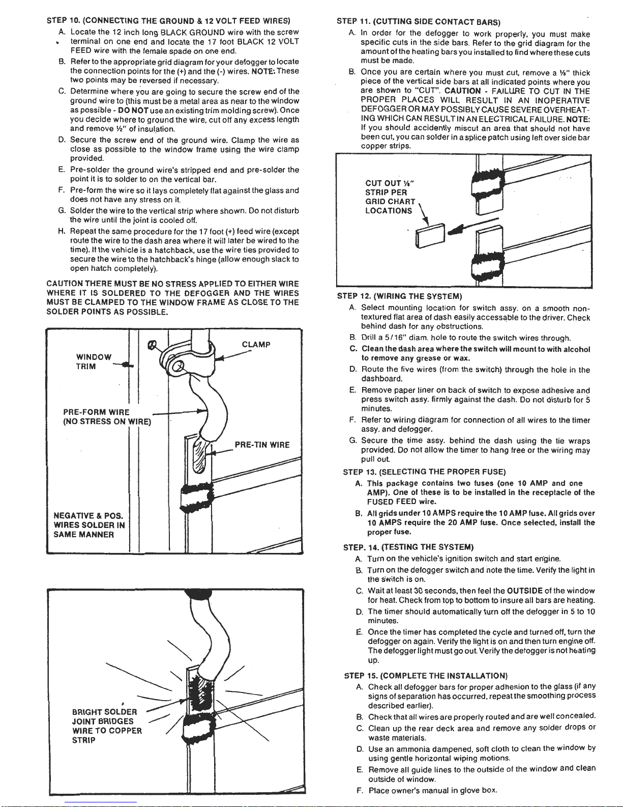
STEP 11. (CUTTING SIDE CONTACT BARS)
A. In order for the defogger to work properly. you must make
specific cuts in the side bars. Refer to the grid diagram for the
amount of the heating bars you installed to find where these cuts
must be made.
B. Once you are certain where you must cut, remove a Y." thick
piece of the vertical side bars at all indicated points where you
are shown to .'CUT". CAUTION -FAILURE TO CUT IN THE
PROPER PLACES WILL RESULT IN AN INOPERATIVE
DEFOGGER OR MA y POSSIBLY CAUSE SEVERE OVERHEAT ING WHICH CAN RESULT IN AN ELECTRICAL FAILURE. NOTE:
Jf you should accidently miscut an area that should not have
been cut, you can solder in a splice patch using left over side bar
copper strips.
STEP 10. (CONNECTING THE GROUND & 12 VOLT FEED WIRES)
A. Locate the 12 inch long BLACK GROUND wire with the screw
terminal on one end and locate the 17 foot BLACK 12 VOL T
FEED wire with the female spade on one end.
B. Refer to the appropriate grid diagram for your defoggerto locate
the connection points for the (+) and the (-) wires. NOTE: These
two points may be reversed if necessary.
C. Determine where you are going to secure the screw end of the
ground wire to (this must be a metal area as near to the window
as possible -DO NOT use an existing trim molding screw). Once
you decide where to ground the wire. cut off any excess length
and remove V2' of insul.ation.
D. Secure the screw end of the ground wire. Clamp the wire as
close as possible to the window frame using the wire clamp
provided.
E. Pre-solder the ground wire's stripped end and pre-solder the
point it is to solder to on the vertical bar.
F. Pre-form the wire so it lays completely flat against the glass and
does not have any stress on it.
G. Solder the wire to the vertical strip where shown. Do not disturb
1he wire until the joint is cooled off.
H. Repeat the same procedure for the 17 foot (+) feed wire (except
route the wire to the dash area where it will later be wired to the
time). If the vehicle is a hatchback, use the wire ties provided to
secure the wire to the hatchback's hinge (allow enough slack to
open hatch completely).
CAUTION THERE MUST BE NO STRESS APPLIED TO EITHER WIRE
WHERE IT IS SOLDERED TO THE DEFOGGER AND THE WIRES
MUST BE CLAMPED TO THE WINDOW FRAME AS CLOSE TO THE
SOLDER POINTS AS POSSIBLE.
~
CLAMP
WINDOW
TRIM
-
PRE-FORM WIRE
(NO STRESS ON WIRE)
PRE- TIN WIRE
NEGATIVE & POS.
WIRES SOLDER IN
SAME MANNER
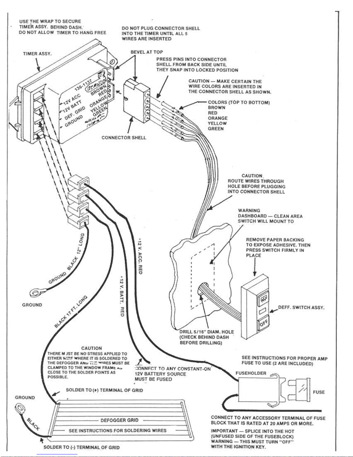
STEP 12. (WIRING THE SYSTEM)
A. Select mounting location for switch assy. on a smooth non-
textured flat area of dash easily accessable to the driver. Check
behind dash for any obstructions. .
B. Drill a 5/16" diam. hole to route the switch wires through.
C. Clean the dash area where the switch will mount to with alcohol
to remove any grease or wax.
D. Route the five wires (from the switch) through the hole in the
dashboard.
E. Remove paper liner on backotswitch to expose adhesive and
press switch assy. firmly against the dash. Do not disturb torS
minutes.
F. Refer to wiring diagram for connection of all wires to the timer
assy. and defogger.
G. Secure the time assy. behind the dash using the tie wraps
provided. Do not allow the timer to hang free or the wiring may
pull out
STEP 13. (SELECTING THE PROPER FUSE)
A. This package contains two fuses (one 10 AMP and one
AMP). One of these is to be installed in the receptacle of the
FUSED FEED wire.
B. All grids under 10 AMPS require the 10 AMP fuse. All grids over
10 AMPS require the 20 AMP fuse. Once selected, install the
proper fuse.
STEP. 14. (TESTING THE SYSTEM)
A. Turn on the vehicle's ignition switch and start en.gine.
B. Turn on the defogger switch and note the time. Verify the light in
the s.witch is on.
C. Wait at least 30 seconds, then feel the OUTSIDE of the window
for heat. Check from top to bottom to insure all bars are heating.
D. The timer should automatically turn off the defogger in 5 to 10
minutes.
E. Once the timer has completed the cycle and turned off, turn the
defogger on again. Verify the light is on and then turn engine off.
The defogger light must go out Verify the defogger is not h&ating
up.
STEP 15. (COMPLETE THE INSTALLATION)
A. Check all defogger bars for proper adhe!;ion to the glass (if any
signs of separation has occurred, repeat the smoothing process
described earlier).
B. Check that all wires are properly routed and are well concealed.
C. Clean up the rear deck area and remove any solder drops or
waste materials.
D. Use an ammonia dampened, soft cloth to clean the window by
using gentle horizontal wiping motions.
E. Remove all guide lines to the outside of the window and clean
outside of window.
F. Place owner's manual in glove box.
Page 4

STEP 6. (SMOOTHING THE HEATING BARS)
Proper adhesion of the heating bars to the glass is critical. Therefore,
before proceeding, you must re-smooth the heating bars by starting in
.the center of each bar and firmly pressing out each strip toward the
edges. Check the outside of the window to insure all lines appear as an
unbroken, solid dark line with no air bubbles or light spots.
STEP 7. (APPLYING THE VERTICAL CONTACT STRIPS)
Locate the small roll of the 318" wide copper contact strips.
A. Unroll a length that will overlap the top and bottom horizontal
bars by 1" (one inch) on each end. Cut the strip off the roll.
B. Using the vertical guideline for alignment, carefully peel away
the paper liner on the back of the copper strip (DO NOT REMOVE
IT COMPLETELY). The dark side applies to the glass.
C. Starting at the top corner, apply the strip to the window and
smooth it as you gradually remove the remainder of the paper
liner as you progress downward.
D. Repeat tilese steps for the other side of the window.
E Smooth out both strips in the same manner as the horizontal
bars.
STEP 9. (SOLDERING THE HORIZONTAL BARS TO THE VERTICAL
BARS)
A F,rst place a heayy drop cloth (not plastic) on the rear deck to
catch any possible solder drops. Use a standard 50 to 60 watt
electric soldering iron for all work.
B. You will be soldering each point where a horizontal bar overlaps
the vertical bar.
C. Use the following standard soldering techniques:
a.) Use 60/40 rosen core solder only -do not use acid core.
b.) The tip of the soldering iron must be clean and bright
c.) Test the iron for proper heat by touching a piece of solder to it
It must melt immediately.
d.) A good solder joint is made in the following manner:
m1.)Touch the tip of the iron to the point being soldered and
hold it there while you count to three slowly (one. ..two. ..
three. ..).
2.) TouCh the solder to the material being soldered (not to the
tip of the iron) and wait for it to flow completely around the
point being soldered.
3.) Remove the piece of solder from thejoint, then remove the
iron.
4.) Do not disturb the joint until it has cooled.
5.) Once cooled, inspect the solder joint It must appear as a
shiny, smooth puddle that bridges all the materials being
soldered, II it has bubbles in it, or it is lumpy and very dull
in color, it must be reheated.
[J
HOT
SOLDERING
IRON
/
SOLDER
/
/1
/
/
/
/
STEP 8. (OVERLAPPING & TRIMMING
A. Starting with the top horizontal bar, carefully Jift up the over-
lapping end and bend it back toward the center of the window,
overlapping the vertical bar-
8. Cut it so the end is even with the inside edge of the vertical bar
and 1hen press it firmly against the vel1ic31 bar. DO NOT CUT
AGAINST ELEMENT.
C. Repeat for all horizontal bars.
Page 5

STEP 1. (PREPARING THE WINDOW)
The inside of the window must be absolutely clean and dry. There is no
compromising of this procedure, for if you do, the defogger elements
will not adhere properly and will begin to peel at a later date.
A. The window must be at least 60-65° F. The adhesive on the
elements will not stick to cold or wet glass. Use a heat gun (or
hair dryer) to warm the window and repeat if the window begins
to cool down.
B. The best cleaning solution to use is "DENATURED ISO-PROPYL
ALCOHOL" which is available at drug stores. The window must
be cleaned twice. Use a clean cloth for each cleaning. Once the
window is completely cleaned, you must remove any residue by
cleaning it once more with AMMONIA based window cleaner
(DO NOT USE chemical cleaners such as "Formula 409" which
leave a soap residue on the glass). Allow the window to dry
thoroughly (use a heat gun if necessary). Avoid touching the
window once it is cleaned. At the same time clean the dash area
where you will mount the on-off switch.
C. II vehicle has a center mounted stop light that will interfere with
the installation of the grid, remove it until grid is installed. NOTE:
It is okay to run grid bars across the stop light area on the glass.
STEP 2. (MARKING THE MOUNTING AREA)
A. All markings must be made on the OUTSIDE of the window using
either a marking pencil or masking tape.
B. Your calculations will indicate the total height the required grid
will require. Using the height dimension provided, mark the top
and bottom horizontal reference lines making certain they are
parallel to eaCh other and to the top of the window.
C. Now mark the left and right vertical side guidelines.
NOTE: For best appearances, the vertical lines should be
parallel to the outside edges of the window.
D. You are now ready to install the defogger.
STEP 4.(APPL YING THE REMAINDER OF THE HORIZONTAL BARS)
Once the first bar is properly installed. you simply apply all additional
bars by the following method:
A. Apply the second strip so the top edge of the clear tape is flush
against the bottom edge of the first strip. Allow end overlaps as in
the first strip.
B. Smooth the second strip in the same manner as the first.
C. Repeat as many times as the application chart indicated for your
vehicle (8 bars. 10 bars. etc.). NOTE: For 14 to 20 bar grids. you
will find a second roll of heating elements in the PRO-0020 kit.
TOP REFERENCE LINE
SIDE REFERENCE LINE
BOTTOM REFERENCE LINE
STEP 5. (REMOVING THE CLEAR TAPE STRIPS)
Use care in removing the clear tape carrier strips to avoid pulling the
heating bar away from the window.
A. Start at one end and lift the clear tape while holding the heating
bar away from the window.
B. Bend the clear tape backward toward the direction you are
pulling to and slowly pull the clear tape away.
C. If the heating bar begins to pull away, immediately stop pulling
and press the bar against the window, then continue.
D. Repeat this procedure until all clear strips dre removed.
STEP 3. (APPLYING THE FIRST HORIZONTAL BAR)
You will find one 65 foot roll of horizontal heating element in this
package.
A. Beginning at the top of the window (use guide line). apply the first
strip in the following manner:
a.) Allow at least one inch of overlap beyond the side guide line.
Align the top edge pf the clear tape with the top guide line.
b.) Unroll one strip completely across the window, smoQthing it
as you progress across the window. CAUTION -DO NOT
STRETCH THE TAPE AS YOU APPL y IT, BUT IT SHOULD BE
TAUT.
c.) Once you have reached the opposite side of the window,
allow one iJIch of overlap and cut off the roll.
d.) You must now smooth the heating bar to insure proper
adhesion to the glass. Begin at the center Of the window and
work outward toward the edges. Do not attempt to smooth out
bubbles in the clear tape as it will be removed later. You are
only concerned with smoothing and applying firm pressure to
the heating bar. NOTE: The best method to use to verify
proper adhesion of the heating bar to the glass is to inspect it
from outside the vehicle. A properly adhered heating bar will
appear as an even. dark line. Any white spots indicate the
h.."tinn h"r n"Ati.. ..rlrlitinn..1 ..mnnthinn
Page 6

4 LINES PER GROUP
SOME UNUSUAL WINDOW APPLICATIONS
SPLIT DOOR VANS
J-UMPER WIRE (USE ELEMENT FEED WIRE PROVIDED)
0
1
20" WIDE
{X) 18" HIGH EACH
WINDOW
REQUIREMENT 12 BARS
EACH WINDOW IN GROUPS OF
2 LINES PER GROUP
TOTAL 24 BARS
TYPICAL CURRENT FOR 12.BAR GRIDS (4 LINES PER GROUP)
NOT RECOMMENDED UNLESS WINDOW IS MORE THAN 80" WIDE
80" WIDE WINDOW = 18 AMPS
TYPICAL CURRENT:
20" WIDE WINDOWS WITH A
TOTAL OF 24 BARS IN GROUPS
OF 2 = 12 AMPS.
HATCHBACKS
(ALL GLASS -NO METAL TO GROUND TO)
NOTE: SINCE HATCHBACKS ARE ALWAYS HINGED AT THE TOP
AND ALL GRip LAYOUTS HAVE THE (+) CONNECTION AND (-)
CONNECTION AT OPPOSITE ENDS OF THE GRID YOU CAN
EASILY BRING BOTH CONNECTIONS TO THE TO'P OF THE GRID
WHERE THE HINGES ARE.
~TO~12 FEED I rTO GROUND I
t ~ GRID ~INGES ~INGES
TOP OF GRID
~ .NEW GROUND
I CONNECTION
-EXTRA PIECE OF
SIDE BAR
NORMAL
CONNECTION
EXTRA PIECE OF SIDE BAR
MAINTAIN ';..'OF SPACE
BETWEEN SIDE BARS TO AVOID
SHORTING.
NOT SHOWN
TYPICAL CURRENT FOR 20-BAR GRIDS (4 LINES PER GROUP
NOT RECOMMENDED UNLESS WINDOW IS MORE THAN 50" WIDE.
50" WIDE WINDOW = 18 AMPS
TYPICAL CURRENT FOR 16-BAR GRIDS (4 LINES PER GROUP)
NOT RECOMMEDED UNLESS WINDOW IS MORE THAN 60" WIDE.
60" WIDE WINDOW = 18 AMPS
Page 7

Page 8

2 LINES PER GROUP
TYPICAL CURRENT FOR 4-BAR GRID (2 LINES PER GROUP)
80" WIDE WINDOW = 13 AMPS
60" WIDE WINDOW = 18 AMPS
6-BAR GRID
4. A final test of the formula:
A. Let's assume we decided to remove one bar from our 13 bar
grid and make it a 12 bar grid.
, B. Now you can see 12 is divisible by 1. 2.3 and 4. So let's
quickly check each grouping possibility to see what
happens:
a. Single grouping (1 bar per group) 12 groups of 1 bar each
.012 (x) 38 (divided by) 1 (x) 12 = 5.4 (13.2 divided by 5.4 =
2.4 AMPS)
This is below the limit
b. Two bar grouping (2 bars per group) 6 groups of 2 bars
each .012 (x) 38 (divided by) 2 (x) 6 = 1.3 (13.2 divided by
1.3 = 10.1 AMPS)
This is within the limits.
c. Three bar grouping (3 bars per group) 4 groups of 3 bars
each .012 (x) 38 (divided by) 3 (x) 4 = 0.6 (13.2 divided by
0.6 = 22 AMPS)
This is above the limits.
d. Four bar grouping (4 bars per group) 3 groups of 4 bars
each .012 (x) 38 (divided by) 4 (x) 3 = 0.3 (13.2 divided by
0.3 = 44 AMPS)
This is way above the limit
C. As you can see, if we had used 12 bars. the only possibility
would be to use 2 bar grouping to make 6 groups of 2 bars
each.
CUT
-J0
TYPICAL CURRENT FOR 6-BAR GRID (2 UNES PER GROUP)
80" WIDE WINDOW = 9 AMPS
40" WIDE WINDOW = 18 AMPS
SOME TYPICAL GRID PATTERNS
NOTE: YOU WILL SEE THAT AS THE WINDOW WIDTH
INCREASES, CURRENT DECREASES
0 3-BAR GRID
CUT 0,
CUT
1-00
TYPICAL CURRENT FOR 8-BAR GRID (2 LINES PER GROUP)
48. WIDE WINDOW= 12AMPS
TYPICAL CURRENT FOR 3-BAR GRIDS {1 LINE PER GROUP)
70" WIDE WINDOW = 6 AMPS
20" WIDE WINDOW = 18 AMPS
1 O-BAR GRID
~
CUT
G) , 4-BAR GRID
CUT D
CUT
CUT
CUT
cuL
G
CUT
-J0
TYPICAL CURRENT FOR 10-BAR GRID (2 LINES PER GROUP)
SO" WIDE WINDOW = 9 AMPS
15" WIDE WINDOW = 18 AMPS
TYPICAL CURRENT FOR 4-BAR GRIDS {1 LINE PER GROUP)
56" WIDE WINDOW = 6 AMPS
15" WIDE WINDOW = 18 AMPS
3 LINES PER GROUP
9-BAR GRID
@
CUT
CUT
.0
TYPICAL CURRENT FOR 9-BAR GRID (3 LINES PER GROUP)
80" WIDE WINDOW = 14 AMPS
60" WIDE WINDOW = 18 AMPS
0r;
ii
CUT
 Loading...