

Audiovox PCR4500CS Owner's Manual

RELEASE
VOLUME
BAND
DSP
MO/ST
SEL
TUNE
LOC
MUT
AM / FM / CASSETTE
PCR4500
POWER
TAPE
PCR4500
Owner's Manual/Manual del Usario/Manual de L'Utilisateur
AM/FM/Cassette Radio
Radio AM/FM/Casete
AM/FM Radio Cassette
PCR4500
2
PREPARATION
Getting Started
It’s a good idea to read all of the instructions
before beginning the installation.
Contents
Installation Instructions.............................. 3
Wiring Diagram.......................................... 5
Installing the Removable Faceplate.......... 6
Operating Instructions............................... 7
Care and Maintenance............................10
Specifications.......................................... 10
90 Day Limited Warranty..........................11
Installation Requirements
This unit is designed for installation in cars,
trucks, and vans with an existing radio opening.
In many cases, a special installation kit will be
required to mount the radio to the dashboard.
These kits are available at electronics supply
stores and car stereo specialty shops. Always
check the kit application before purchasing to
make sure the kit works with your vehicle. If you
need a kit but cannot locate one, call our
customer support line at 1-800-323-4815.
(U.S.A. and Canada only.)
Tools and Supplies
The following tools and supplies are needed to
install the radio.
• Torx type, flathead and Philips
screwdrivers
• Wire cutters and strippers
• Tools to remove existing radio
(screwdriver, socket wrench set or other
tools)
• Electrical tape
• Crimping tool
• Volt meter/test light
• Crimp connections
• 18 gauge wire for power connections
• 16-18 gauge speaker wire
Speaker Requirements
Only connect speakers rated with a load
impedance of 4 ohms. Speakers with a load
impedance of less than 4 ohms could damage
the unit.
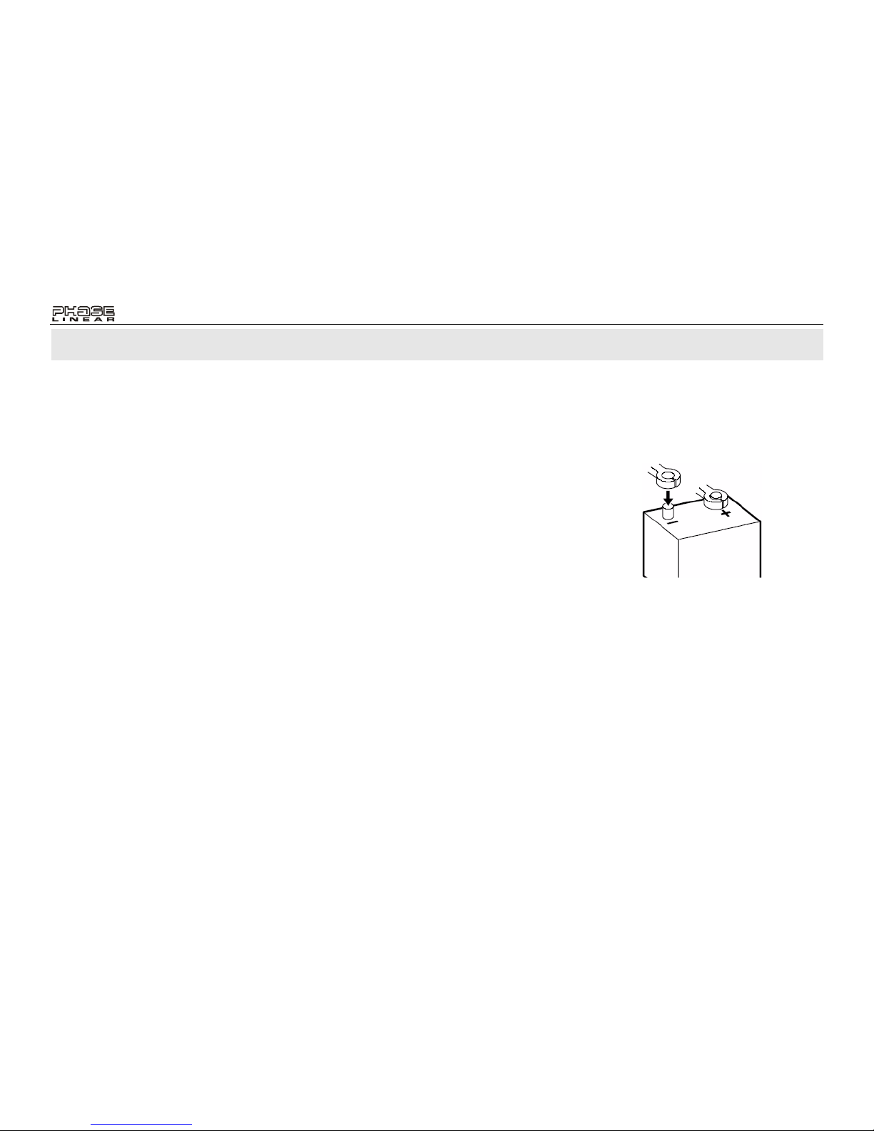
Disconnect Battery
Before you begin, disconnect the battery
negative terminal.
Toll-Free Installation Assistance
If you require assistance, contact Technical
Support at 1-800-323-4815 from 8:30 a.m. to
7:00 p.m. EST Monday through Friday and from
9:00 a.m. to 5:00 p.m. EST on Saturday.
(U.S.A. and Canada only.)
Pour des instructions en Francais, référez-vous à la page 26.
Para obtener instrucciones en Espa
ñol, diríjase a la página 14.
PCR4500
3
INSTALLATION INSTRUCTIONS
Do You Need an Installation Kit?
Inspect the radio opening as described below to
determine if you need an installation kit.
1. Use the trimplate supplied with the radio to
cover the existing dashboard opening. If it
completely covers the opening, you can
install the radio without an installation kit. If
it does not cover the opening, you will
need an installation kit (see page 4).
2. Check for sufficient space behind the
dashboard for the radio chassis.
Using a Mounting Sleeve
1. Slide the mounting sleeve off the chassis.
If it is locked into position, use the removal
tools (supplied) to disengage it.
2. Check the dashboard opening size by
sliding the mounting sleeve into it.
Carefully cut or file as necessary until the
sleeve easily slides into the opening. Do
not force the sleeve or cause it to bend or
bow. Check for sufficient sp ace behind the
dashboard for the radio chassis.
3. Locate the series of bend tabs along the
top, bottom, and sides of the mounting
sleeve. With the sleeve fully inserted into
the dashboard opening, bend as many of
the tabs outward as necessary to firmly
secure the sleeve to the dashboard.
4. Place the radio in front of the dashboard
opening and bring the wires through the
mounting sleeve. Follow the wiring
diagram carefully, making certain all
connections are secured with wire nuts or
electrical tape. After completing the wiring
connections, turn the unit on to confirm
operation (vehicle ignition must be “on”). If
the unit does not operate, re-check all
wiring until the problem is corrected.
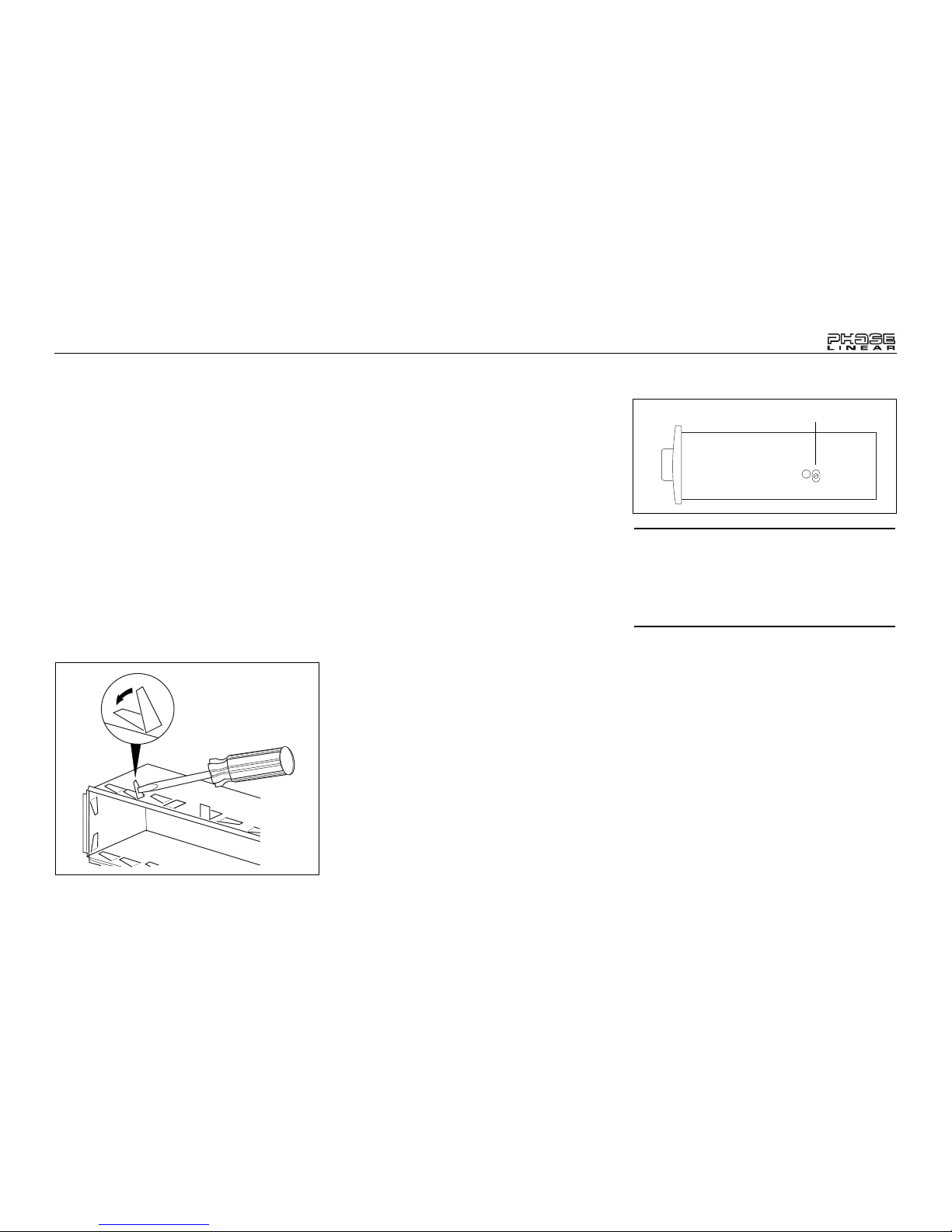
5. Adjust the AM Antenna Trimmer, located
on the right side of the chassis, for optimum AM reception.
a. Tune in a weak station around 1400
KHz on the AM band.
b. Use a small screwdriver to adjust the
trimmer for maximum output.
NOTE: The Antenna Trimmer only affects
AM reception and will have no effect on FM
reception. The Trimmer should only need
adjusting when the radio is first installed
and when a change is made to the vehicle
antenna (replacing the mast, etc.).
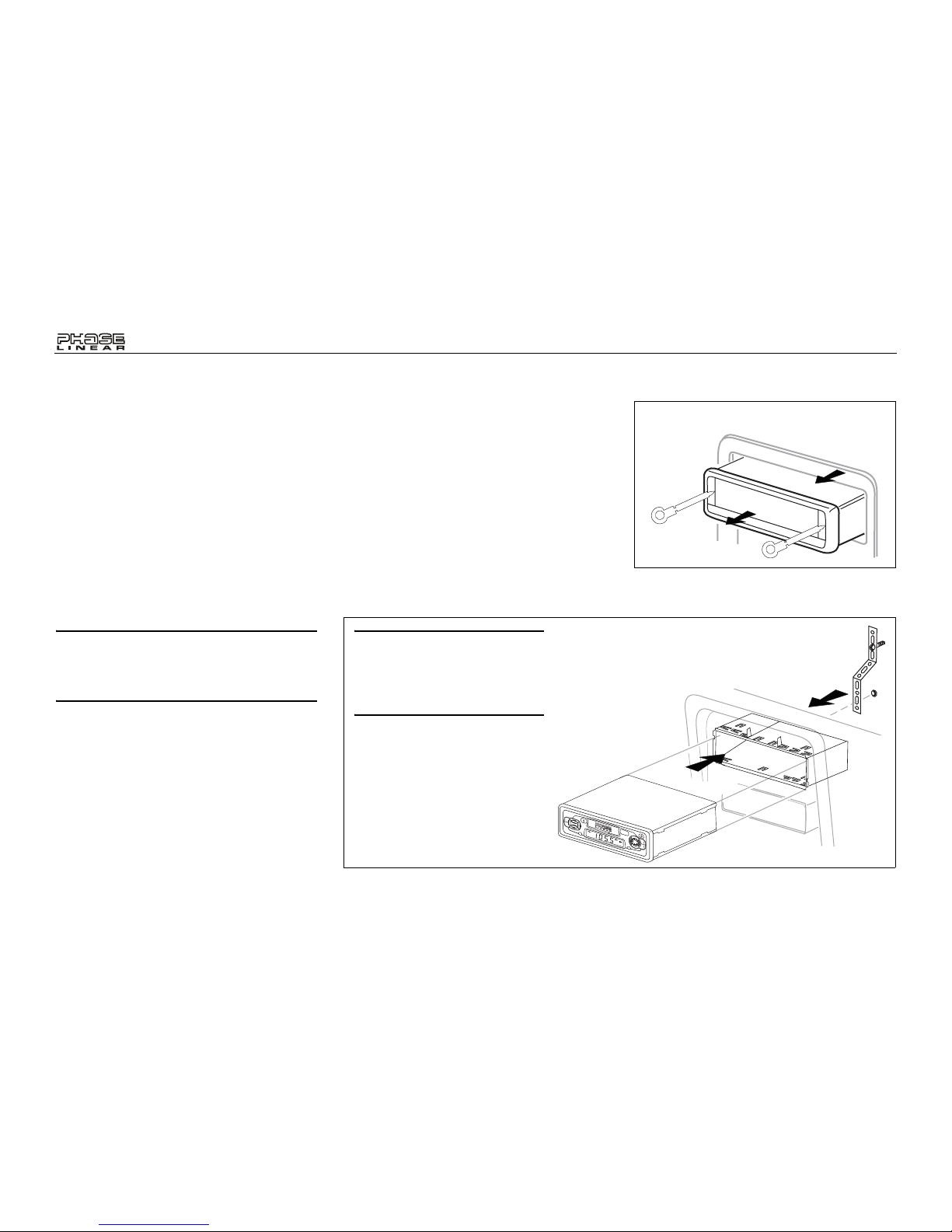
6. Make sure the radio is right-side up, then
carefully slide the radio into the mounting
sleeve until it is fully seated and the spring
clips lock it into place.
7. Attach one end of the perforated support
strap (supplied) to the screw stud on the
rear of the chassis using the hex nut
provided. Fasten the other end of the
perforated strap to a secure part of the
dashboard, either above or below the
radio, using the screw provided. Bend the
strap to position it as necessary.
8. Test the radio using the Operating
Instructions that follow.
AM ANTENNA TRIMMER
BEND TABS
PCR4500
4
INSTALLATION INSTRUCTIONS
Installation Using a Kit
If your vehicle requires the use of an installation
kit to mount this radio, follow the instructions
included with the installation kit to attach the
radio to the mounting plate supplied with the kit.
1. Wire and test the radio as described in
step 4 of “Using a Mounting Sleeve” on
page 3.
2. Install the radio mounting plate assembly
to the sub-dashboard according to the
installation kit instructions.
3. Attach the support strap to the radio and
dashboard as described in step 7 of
“Using a Mounting Sleeve” on page 3.
CAUTION: The support strap must be used
to prevent damage to the dashboard from
the weight of the radio or improper
operation due to vibration.
4. Replace the dashboard trim panel.
Removing the Radio
To remove the radio after installation, remove
the trim ring by lifting in the center and pulling it
off from either side. Insert the removal keys
straight back until they lock, then pull the radio
out. If removal keys are inserted at an angle,
they will not lock properly and will not release
the unit.
R
E
L
E
A
S
E
V
O
L
U
M
E
B
A
N
D
DSP
M
O
/S
T
SEL
TUNE
LOC
MUT
A
M
/
F
M
/
C
A
S
S
E
T
T
E
P
C
R
4
5
0
0
POWER
TAPE
CAUTION: For proper operat ion
of the CD player, the chassis
must be mounted within 20° of
horizontal. Make sure the unit is
mounted within this limitation.
INSTALLATION
REMOVING THE RADIO
PCR4500
5
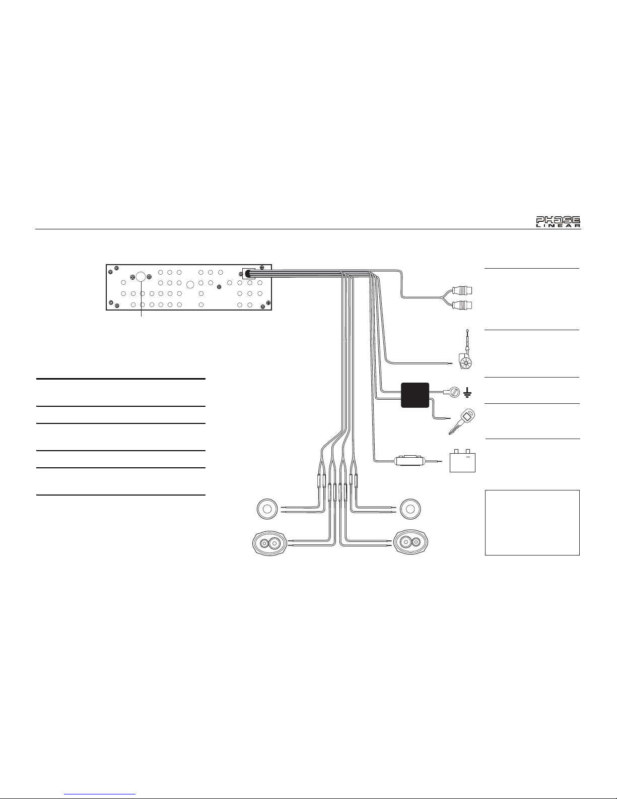
Antenna Connector
Power Antenna
Connect to power antenna
or amplifier. If not used, tape
bare end of wire.
Ground
Connect to ground terminal.
Memory/Battery
Connect to battery or 12 volt
power source that is always
live. The radio will not work
if this wire is not connected.
Accessory/Ignition
Connect to existing radio
wire or radio fuse.
Amplifier Wiring
Connect line out for optional
external amplifiers. The red
connector is for the right
and the white connector is
for the left.
Gray
+
Blue
Black
White/Black (-)
White (+)
Gray/Black (-)
Gray (+)
Violet (+)
Green (+)
Green/Black (-)
Violet/Black (-)
LF/AVG
RF/AVD
LR/ARG
RR/ARD
Fuses
When replacing a fuse, make
sure the new fuse is the correct
type (AGC) and amperage.
Using an incorrect fuse could
damage the radio.
Yellow
3A
Red
FILTER&
FUSE BOX
WIRING
WARNING! Never combine (bridge) outputs
for use with 1 speaker.
WARNING! Never ground negative speaker
leads to chassis ground.
CAUTION: Failure to wire exactly as shown
may cause electrical damage.
PCR4500
6
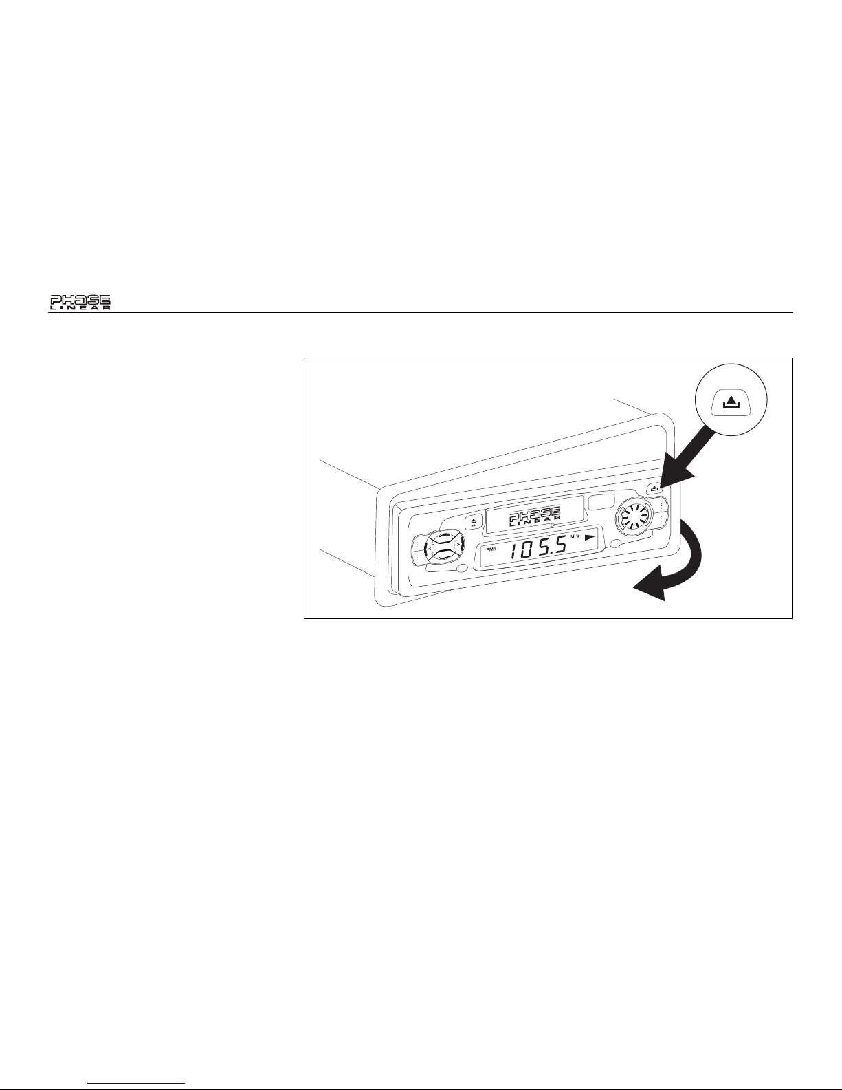
INSTALLING THE REMOVABLE FACEPLATE
Faceplate Installation
To install the faceplate, slip the left edge of the
front panel into the radio then gently press the
right side into place.
Faceplate Detachment
To remove the faceplate, press the RELEASE
button, and pull gently on the right side of the
front panel.
For safekeeping, store the front panel in the
protective case provided.
Handling Precautions
• Make sure the front panel is right-side-up
when attaching it to the chassis as it
cannot be attached when up-side down.
• Do not press very hard on the front panel
when attaching it to the chassis. No more
than light to moderate pressure is needed.
• When attaching the front panel, make sure
it is centered in the chassis frame and is
pressed straight into position.
• Do not drop the front panel.
• Do not put pressure on the display or
control buttons when handling the front
panel.
• Do not touch the electrical terminals on the
front panel or main unit.
• Remove dirt or foreign substances with a
clean, dry cloth only.
• Do not expose the front panel to extreme
temperatures or direct sunlight.
• Keep volatile agents such as benzene,
thinner, or insecticides away from the front
panel.
• Do not disassemble the front panel.
• When taking the front panel with you,
please use the supplied carrying case to
protect the panel from dirt and damage.
• Make sure there is no dust or dirt on the
electrical terminals on the back of the
panel as this could cause intermittent
operation or other malfunctions.
RELEASE
VOLUME
BAND
DSP
MO/ST
SEL
TUNE
LOC
MUT
A
M
/
F
M
/
C
A
S
S
E
T
T
E
PCR4500
POWER
TAPE
RELEASE
PCR4500
7
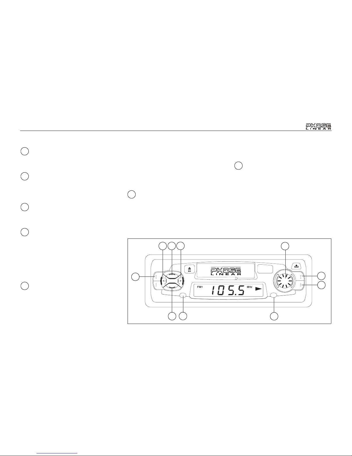
OPERATING INSTRUCTIONS
Power Button
Press the POWER button (1) to turn the unit on
or off.
Volume Control
Press the VOLUME > button (2a) to increase
the volume or the VOLUME < button (2b) to
decrease the volume.
AM/FM Band Selector
Press the BAND button (3) to switch the radio
band between “AM” and “FM”.
Manual Tuning Control
Rotate the TUNE knob (4) to the left or right to
select the desired radio station. When tuning in
a station, always adjust the control so that you
are receiving the full signal and are on the
center of the broadcast frequency. If the radio is
not on frequency, you could experience noise
and reception problems.
Select Button (SEL)
The SEL button is used to select the audio
function (volume, bass, treble, balance or fade)
to be adjusted using the VOLUME control (2).
Press the SEL button (5) once to set the unit for
volume adjustment (“Vo” will appear on the
display panel). Press the button additional
times to select bass adjustment (“bA” on
display panel), treble adjustment (7), balance
(b), fader (F), and volume (Vo) again. The
display will return to the normal indication 5
seconds after the last adjustment or when
another function is activated.
Bass Control
To adjust the bass level, first select the Bass
mode by pressing the SEL button (5) until “bA”
appears on the display panel. Within five
seconds, press the VOLUME buttons (2a and
2b) to adjust the bass response from a
minimum of “bA -7” to a maximum of “bA 7”.
“bA 0” represents a flat response.
Treble Control
To adjust the treble level, press the SEL button
(5) until “7” appears on the display panel. Within
five seconds, press the VOLUME buttons (2a
and 2b) to adjust the treble from a minimum of
“7 -7” to a maximum of “7 7”. “7 0” represents a
flat response.
1
2
3
4
5
5
5
RELEASE
VOLUME
BAND
DSP
MO/ST
SEL
TUNE
LOC
MUT
AM / FM / CASSETTE
PCR4500
POWER
TAPE
12
8
7
6
5
2b
2a
3
4
1
PCR4500
8
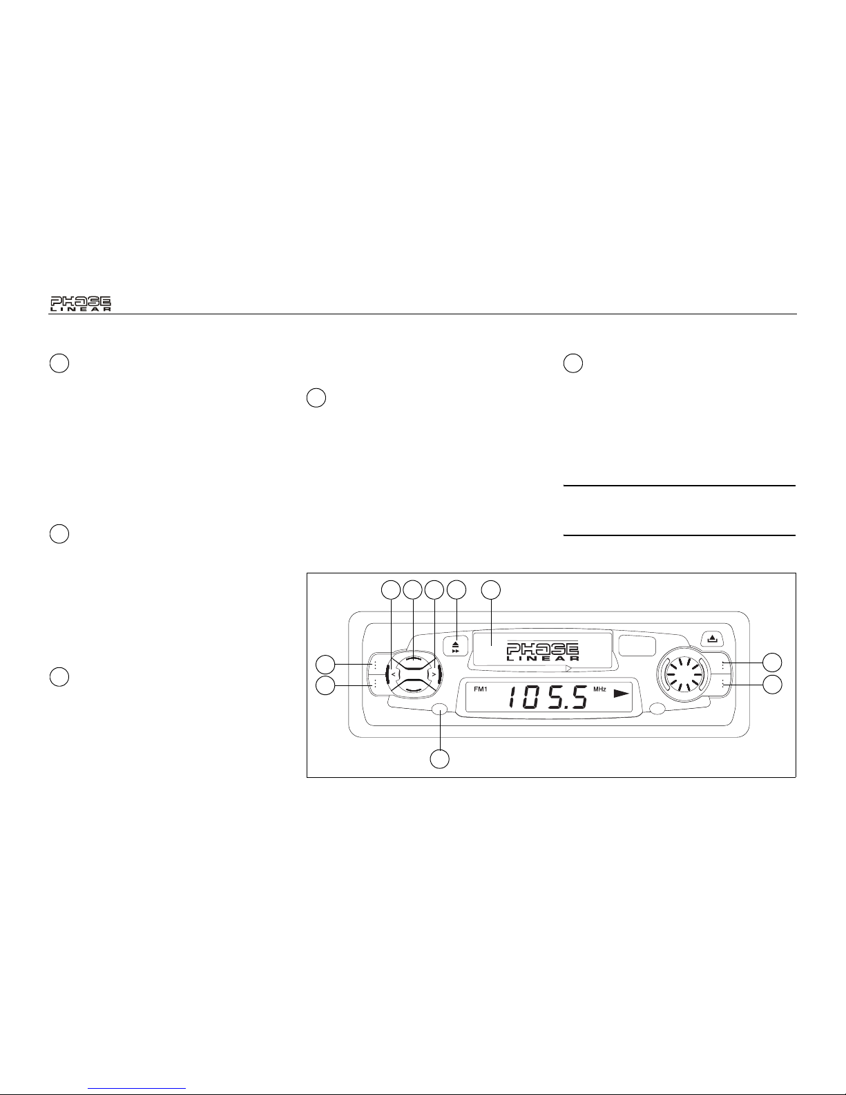
OPERATING INSTRUCTIONS
Left/Right Balance Control
To adjust the left-right speaker balance, press
the SEL button (5) until the “b” indication
appears on the display panel (if not equally
balanced, “bL” or “br”, followed by the balance
level, will appear). Within five seconds, press
the VOLUME buttons (2a and 2b) to adjust the
balance between the left and right speakers
from “bL 15” (full left) to “br 15” (full right). “b 0”
represents an equal balance level between the
left and right speakers.
Rear/Front Fader Control
To adjust the front/rear speaker balance, press
the SEL button (5) until “F“ appears on the
display panel. Within five seconds, press the
VOLUME buttons (2a and 2b) to adjust the
balance between the rear and front speakers
from “Fr 10” (full rear) to “FF 10” (full front). “F
0” represents an equal balance level between
the rear and front speakers.
FM Mono/Stereo Button
(MO/ST)
During FM radio reception, press the MO/ST
button (6) to select mono or stereo reception.
Under normal reception conditions, the unit
should be left in the stereo mode, as indicated
by the “ST” indicator. If the stereo signal is too
noisy for comfortable listening, press the MO/
ST button to switch to mono reception.
Local Button (LOC)
During radio operation, received signals are
usually in stereo mode as indicated by the “ST”
icon; however, when the signals are weak or
intermittent, you can activate the Local (LOC)
mode by pressing the LOC button (7). “LOC”
appears on the display. This mode favors
access to local stations whose signals are
much stronger; thereby improving radio
reception. Press the LOC button again to
terminate Local receive mode (“LOC”
disappears from the display panel).
Audio Mute (MUT)
Press the MUT button (8) to mute the volume
from the system. The display will flash and the
volume will be muted. Press the MUT button
again, press the VOLUME buttons (2a or 2b),
or press the SEL button (5) to return the volume
level to the setting in use before the Mute
function was activated.
NOTE: The local/distant selector only
affects FM signals, and will have no effect
on AM reception.
5
5
6
7
8
RELEASE
VOLUME
BAND
DSP
MO/ST
SEL
TUNE
LOC
MUT
AM / FM / CASSETTE
PCR4500
POWER
TAPE
8
7
10
11
5
12
6
2b
2a
9

PCR4500
9
OPERATING INSTRUCTIONS
Display Selector (DSP)
This unit can display either the clock or radio
frequency/CD player functions. Ordinarily, the
radio frequency or CD player track indication is
displayed, but the unit will display the time
when the DSP button (9) is pressed. The time
will display for approximately 5 seconds then
return to the radio or CD player function display.
The correct time-of-day can be set by pressing
and holding the DSP button. This procedure is
explained in the next step.
Setting the Clock
To set the clock, perform the following steps:
1. Turn the vehicle ignition and radio on.
2. Press and hold the DSP button (9) until
the time display flashes.
3. Within 5 seconds, press the VOLUME >
button (2a) to adjust the minutes.
4. Press the VOLUME < button (2b) to adjust
the hour and the “AM”/”PM” indication to
the desired time.
Five seconds after the last hour or minute
adjustment has been made, the time will be set
in the unit and normal operation will resume.
Cassette Door
Hold the cassette with the exposed tape edge
to the right and insert it into the cassette door.
Depress fully until the cassette is engaged and
begins playing.
NOTE: Observe the cassette operation
cautions in the Care and Maintenance
section of this manual.
Fast-Forward/Eject Button
The fast-forward/eject button (11) performs two
functions.
• To eject a cassette, press the button fully
then release. The cassette will eject and
radio operation will resume.
• To fast-forward the tape, press the button
half-way until it locks into position. To stop
fast-forward and resume normal tape
playback, press the button slightly and
release. Do not depress fully in or the
cassette will be ejected.
Tape Button
Press the TAPE button (12) to change from AM
or FM mode to Tape mode. To return to AM or
FM mode, press the BAND button (3).
NOTE: Never leave a cassette engaged in
the player when not in use. Doing so can
cause damage to the cassette and/or
mechanism of the unit. Always press the
eject button and remove the cassette when
leaving the vehicle.
9
10
11
12
PCR4500
10
CARE AND MAINTENANCE/SPECIFICATIONS
The radio portion of your new sound system
does not require any maintenance. We
recommend you keep this manual to reference
instructions regarding the many features of this
unit. As with any cassette player, the cassette
section of this sound system does require a
minimum of maintenance to keep it in good
working condition. The following simple care
and maintenance suggestions should be
followed to prevent malfunctions of the cassette
system.
• Purchase a cassette cleaning kit from your
local retail store and use it! After every 20
to 30 hours of operation you should clean
the cassette mechanism to maintain
optimum sound.
• Do not use cassettes that exceed 45
minutes of play on each side.
• Do not insert a cassette that appears to be
broken, twisted, dirty or has loose or torn
labels on it.
• Always keep your cassettes away from
direct sunlight or exposure to sub-freezing
conditions. If a cassette is cold, allow it to
warm up before use.
• Do not keep a cassette in the player when
not in use.
• Before inserting a cassette in the player,
check that the tape is tightly wound on the
reels. Take up any excess slack using a
pencil to turn the drive hub in the cassette.
Technical Specifications
CEA Power Ratings
Power Output: 6 watts RMS X 4 channels into
4-ohms @ < 1% THD+N
Signal to Noise Ratio: 70dBA below reference.
(Reference: 1 watt, 4-ohms)
Frequency Response: 20Hz to 20kHz, -3dB
Reference Supply Voltage: 14.4VDC
FM Tuner
Tuning Range: 87.5MHz - 107.9MHz
Mono Sensitivity: 18dBf
50dB Stereo Quieting Sensitivity: 20dBf
Stereo Separation @ 1kHz: >30dB
Frequency Response: 30Hz to 12kHz, -3dB
AM Tuner
Tuning Range: 530kHz - 1710kHz
Sensitivity @ 20dB Signal to Noise: 30uV
Frequency Response: 30Hz - 2kHz, -3dB
General
Power Supply: 11 to 16VDC, negative ground
Fuses: Battery - 3 amp/AGC, Ignition/
Accessory - 5 amp/AGC
4 + 9 pin quick-connect harness
Dimensions: 7" X 7" X 2" (178mm x 178mm x
51mm)
Specifications subject to change without
notice.

PCR4500
11
90 DAY LIMITED WARRANTY
AUDIOVOX CORPORATION (the Company)
warrants to the original retail purchaser of this
product that should this product or any part
thereof, under normal use and conditions, be
proven defective in material or workmanship
within 90 days from the date of original
purchase, such defect(s) will be repaired or
replaced with new or reconditioned product (at
the Company's option) without charge for parts
and repair labor. To obtain repair or
replacement within the terms of this Warranty,
the product is to be delivered with proof of
warranty coverage (e.g. dated bill of sale),
specification of defect(s), transportation
prepaid, to the warranty center at the address
shown below.
This Warranty does not extend to the
elimination of car static or motor noise, to
correction of antenna problems, to costs
incurred for installation, removal, or
reinstallation of the product, or damage to
tapes, compact discs, accessories or vehicle
electrical systems. This Warranty does not
apply to any product or part thereof which, in
the opinion of the Company, has suffered or
been damaged through alteration, improper
installation, mishandling, misuse, neglect,
accident, or by removal or defacement of the
factory serial number/bar code label(s) or
markings. THE EXTENT OF THE COMP ANY'S
LIABILITY UNDER THIS WARRANTY IS
LIMITED TO THE REPAIR OR
REPLACEMENT PROVIDED ABOVE AND, IN
NO EVENT, SHALL THE COMPANY'S
LIABILITY EXCEED THE PURCHASE PRICE
PAID BY PURCHASER FOR THE PRODUCT.
This Warranty is in lieu of all other express
warranties or liabilities. ANY IMPLIED
WARRANTIES, INCLUDING ANY IMPLIED
WARRANTY OF MERCHANTABILITY, SHALL
BE LIMITED TO THE DURATION OF THIS
WRITTEN WARRANTY. ANY ACTION FOR
BREACH OF ANY WARRANTY HEREUNDER
INCLUDING ANY IMPLIED WARRANTY OF
MERCHANTABILITY MUST BE BROUGHT
WITHIN A PERIOD OF 30 MONTHS FROM
DATE OF ORIGINAL PURCHASE. IN NO
CASE SHALL THE COMPANY BE LIABLE
FOR ANY CONSEQUENTIAL OR
INCIDENTAL DAMAGES FOR BREACH OF
THIS OR ANY OTHER WARRANTY,
EXPRESS OR IMPLIED, WHATSOEVER. No
person or representative is authorized to
assume for the Company any liability other than
expressed herein in connection with the sale of
this product.
Some states do not allow limitations on how
long an implied warranty lasts or the exclusion
or limitation of incidental or consequential
damage so the above limitations or exclusions
may not apply to you. This Warranty gives you
specific legal rights and you may also have
other rights which vary from state to state.
U.S.A: Audiovox Corporation, 150 Marcus
Blvd., Hauppauge, NY 11788, 1-800-323-4815
CANADA: Call 1-800-323-4815 for location of
warranty station serving your area.
Audiovox Electronics Corporation
150 Marcus Boulevard
Hauppauge, NY 11788
1-800-323-4815
www.audiovox.com
©2005 Audiovox
v.011505
 Loading...