

Page 1
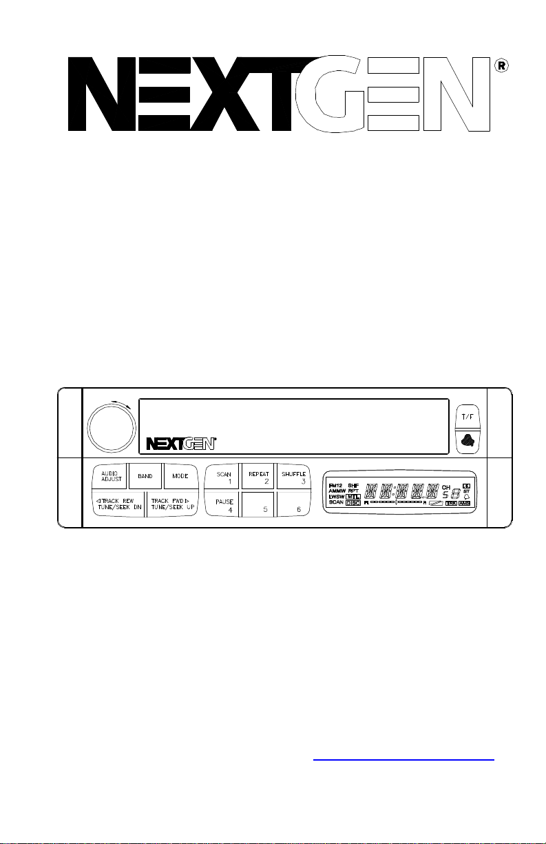
PUSH
ON/OFF
VOL/AUDIO
ADJ
INSTALLATION
MANUAL
HEAVY-DUTY VEHICLE
ENTERTAINMENT SYSTEM
Audiovox Specialized Applications, LLC
23319 Cooper Drive
Elkhart, IN 46514
1-800-688-3135
www.asaelectronics.com
Page 2
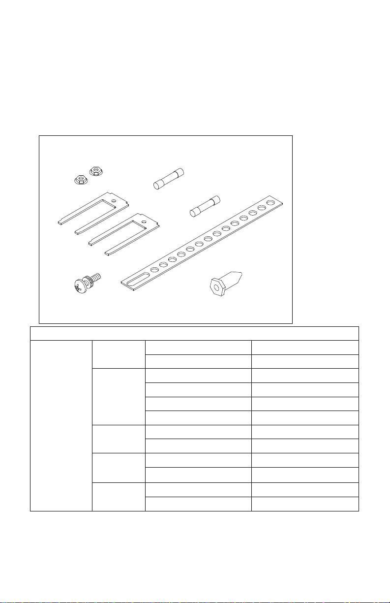
Content List:
1) Nextgen Main Chassis
2) Hardware Kit
3) Wiring Harness
4) Installation Manual
Hardware Kit
FLANGE NUTS
5 AMP
1 AMP
DIN SLEEVE
REMOVAL TOOL
MOUNTING SCREW
From
4-Pin
Harness
Pair
Pair
Pair
2-Bond
Pair
MOUNTING STRAP
MOUNTING BUSHING
Wiring Color Code
Gray Left Front (-)2-Bond
Gray/White Left Front (+)
Orange/White Ignition
Black Chassis Ground
Pink 12V Out 100mA
Green/White Memory
Gray Right Front (-)2-Bond
Gray/Blue Right Front (+)
Gray Right Rear (-)2-Bond
Gray/Red Right Rear (+)
Gray Left Rear (-)
Gray/Yellow Left Rear (+)
1
Page 3

INSTALLATION INSTRUCTIONS- DIN RADIO
This unit is designed for installation in vehicle cabs with an existing radio
opening. In many cases, a special installation kit will be required to
mount the radio to the dashboard. These kits are available at electronics
supply stores and car stereo specialist shops. Always check the kit
application before purchasing to make sure the kit works with your
vehicle.
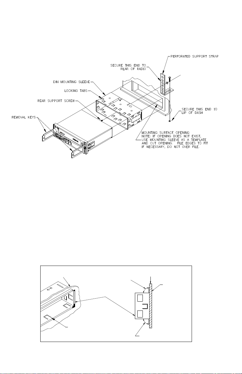
UNIVERSAL INSTALLATION PROCEDURE USING
MOUNTING SLEEVE
1) Remove endcaps and slide the mounting sleeve off of the chassis. If
it is locked into position, use the removal tools (supplied) to
disengage it.
2) Check the dashboard opening size by sliding the mounting sleeve
into it. If the opening is not large enough, carefully cut or file as
necessary until the sleeve slides easily into the opening. Do not
force the sleeve into the opening or cause it to bend or bow. Check
that there will be sufficient space behind the dashboard for the radio
chassis. Connect wires prior to actually installing the sleeve. Pigtail
wiring should take place after hole size is confirmed. Mount sleeve
after wiring.
3) Follow the wiring diagram carefully and make certain all connections
of the wiring harness are properly secured and insulated to insure
proper operation of this unit. After completing the wiring
connections, turn the unit on to confirm operation (ignition switch
must be “on”). If unit does not operate, recheck all wiring until the
problem is corrected. Once proper operation is achieved, turn off
ignition switch and proceed with final mounting of the chassis.
4) Locate the series of bend tabs along the top, bottom, and sides of
the mounting sleeve. With the sleeve fully inserted into the dash
opening, bend tabs outward so that the sleeve is firmly secured to
the dashboard.
5) Carefully slide the radio into the mounting sleeve making sure it is
right side up until it is fully seated and the spring clips lock it into
place.
6) Attach one end of the perforated mounting strap (supplied) to the
screw stud on the rear of the chassis using the flange nut provided.
Fasten the other end of the perforated strap to a secure part of the
dashboard, either above or below the radio using the screw and
flange nut provided, bend the strap to position as necessary.
2
Page 4
CAUTION: The rear of the radio must be supported with the strap to
prevent damage to the dashboard from the weight of the
radio or improper operation due to vibration.
INSTALLATION USING KITS
1. If your radio requires the use of an installation kit to mount this radio,
follow the instructions included in the kit to attach the radio to the
mounting plate supplied with the kit.
2. Wire and test the radio as described in step 3 on page 2.
3. Install the radio/mounting plate assembly to the sub-dash according
to the instructions of the installation kit.
4. Attach the support strap to the radio and dashboard as described in
step 6 on page 2.
5. Replace the dashboard trim panel.
CUTAWAY VIEW OF
MOUNTING SURFACE
BEND TABS
MOUNTING TAB DETAILS
TOP TAB BEND
UPWARD 90°
MOUNTING
SLEEVE
3
SIDE VIEW
MOUNTING
SURFACE
BOTTOM TAB
BEND DOWNWARD 90°
Page 5

NEXTGEN CONFIGURATION
The Nextgen radio can be programmed to change options and factory
settings. Follow the steps outlined in the following pages to modify the
radio as required for the options installed and for the mode of operation
intended.
SETTING THE CLOCK FOR 12 OR 24 HOUR DISPLAY
Hold down the AUDIO ADJUST button for greater than 3 seconds. The
unit will then enter the general configuration menu. You should see CL24 or CL-12. To select 12 hour clock operation, press the manual “tune
up/track forward” button once or until CL-12 is displayed. If 24-hour
clock operation is desired, press the manual “tune up/track forward”
button until CL-24 is displayed. You can either press AUDIO ADJUST
again or let the configuration menu timeout, within about 5 seconds.
CONFIGURATION OF AUXILLARY LOW-LEVEL AUDIO INPUT
Hold down the AUDIO ADJUST button for greater than 3 seconds. The
unit will enter the general configuration menu. Press the manual “tune
down/track down” button until you see “IN--**”. To configure the radio to
accept low-level audio signal, scroll through menu items until “AUX--**”
(where ** can equal Y or N) is displayed. Use the manual “tune up/track
forward” button to change the option to “AUX-Y”. To disable this feature,
use the manual “tune up/track forward” button to change back to “AUXN”. To exit configuration, press AUDIO ADJUST or let the menu timeout,
within about 5 seconds.
4
Page 6

CONFIGURATION con’t.
CONFIGURATION OF WORLD BAND TUNER
Hold down the AUDIO ADJUST button for greater than 3 seconds. The
unit will then enter the general configuration menu. To enter the tuner
configuration menu, press preset 4, then preset 2. “CC--**” will show up
on the display (where ** can equal 11, 12, 14, 15, 16, or 21). Use the
manual “tune up/track forward” button to select the proper country code
for the region of interest. The country codes are listed below. To exit the
configuration menu press AUDIO ADJUST or let the menu timeout,
within about 5 seconds.
Country Code Country Band Low High Step
11 North America AM
FM
12 Europe SW
AM
FM
LW
13 Pacific AM
FM
14 Japan AM
FM
15 Latin America AM
FM
16 Brazil AM
FM
21 Saudi Arabia AM
FM
530
87.9
5900
531
87.50
144
531
87.5
522
76.0
530
88.0
530
87.9
531
87.5
1710
107.9
6200
1629
108.00
288
1629
108.0
1629
90.0
1600
108.0
1620
107.9
1602
108.0
10kHz
200kHz
5kHz
9kHz
50kHz
9kHz
9kHz
100kHz
9kHz
100kHz
10kHz
100kHz
10kHz
200kHz
9kHz
50kZHz
CONFIGURATION OF 2 AND 4 SPEAKER OPERATION
Hold down the AUDIO ADJUST button for longer than 3 seconds. The
unit will then enter the general configuration menu. Press the manual
“tune down/track down” button until you see “SP--**” displayed on the
readout (where ** can equal 2 or 4). Depending upon your setup, you’ll
change this menu item accordingly, using the manual “tune down/track
down” button to modify the setting to either “SP-2” or “SP-4”. Once
configured to your particular setup, exit the configuration menu by
pressing the AUDIO ADJUST or letting the menu timeout, within about 5
seconds.
6
Page 7

CONFIGURATION- con’t.
CONFIGURATION OF TUNER SEEK SENSIVITY SETTING
The scan sensitivity feature is designed to give flexibility during the tuner
seek function. The tuner can be configured such that during seek, it will
stop on strong stations, ignoring weaker signals. The tuner can also be
configured to stop at all weak signals.
To configure the seek sensitivity setting, hold down the AUDIO ADJUST
button for longer than 3 seconds. The unit will then enter the general
configuration menu. While in the general configuration menu, press
preset 4 and then preset 2. The unit is now in the tuner configuration
menu. Press the manual “tune down/track down” button until you see
“SC--**” on the display (where ** can equal 00-15). The numbers are set
such that at the setting “SC-00”, the unit is more sensitive to weaker
signals. This means that the seek function will stop at most or all weak
signals. At “SC-15”, the seek function will stop only at the strong
stations. Use the manual “tune up/track forward” button to adjust the
seek sensitivity of the tuner to a setting that will suit the application. To
exit the tuner configuration menu, press AUDIO ADJUST or let the menu
timeout, within about 5 seconds. For reference the factory setting is 08.
CONFIGURATION OF THE MECHANICAL CASSETTE MODULE
Hold down the AUDIO ADJUST button for longer than 3 seconds. The
unit will enter the general configuration menu. Press manual “tune
down/track down” button until you see “IN--**”. For logic cassette, scroll
through the menu options until “IN--**” (where ** can equal NA, LT, CD,
or CG) is displayed. For proper mechanical cassette operation, this
setting should be set to “IN-NA”. If this button setting is not “IN-NA”,
press the manual “tune up/track forward” button until this appears on the
display. To exit configuration, press the AUDIO ADJUST or let the menu
timeout, within about 5 seconds.
6
Page 8

WIRING DIAGRAM
See page 1 for color code
SEE PAGE 4 FOR LOW
LEVEL AUDIO INPUT
PINK (TRIGGER) - SEE CHART C
*SPEAKER WIRES ARE BONDED PAIRS
NEGATIVE GRAY WIRES PAIRED
WITH RESPECTIVE POSITIVES
*SOLDER AND TAPE ALL SPLICES
BLACK/WHITE (GROUND)
GREEN/WHITE (BATTERY +12V) - SEE CHART A
ORANGE/WHITE (ACC. +12V) - SEE CHART B
LEFT FRONT SPEAKER
DIN CONNECTOR
9 PIN CABLE
CONNECTOR
TO ANTENNA
4 PIN CABLE
CONNECTOR
RIGHT FRONT SPEAKER
4 OR 8 OHM
LEFT REAR SPEAKER
4 OR 8 OHM
GRAY (-)
GRAY/WHITE (+)
GRAY (-)
GRAY (-)
GRAY/BLUE (+)
4 OR 8 OHM
RIGHT REAR SPEAKER
GRAY (-)
GRAY/YELLOW (+)GRAY/RED (+)
4 OR 8 OHM
7
Page 9

WIRING DIAGRAM – con’t.
CAUTION- Connect all speakers before turning the radio on. This radio
is designed to operate with a minimum of two speakers.
CHART A-
Green/White Wire
This wire maintains the pre-set memories and clock time.
CHART B-
Orange/White Wire
This wire is connected to the “Accessory “ or “On” position of the key
switch. The radio will then only operate when the switch is “On” and will
automatically shut-off when the key is turned off. If a key switched
connection is not possible, this wire may be connected to a constant
+12V source. If this is the case, the radio must be manually turned “Off”
after use to prevent excessive battery drain.
CHART C-
Pink Wire
This wire provides a source of +12 volts only when the radio is turned
on. It may be used to turn on an optional power amplifier (See
instructions provided with the amplifier) or activate an automatic power
antenna to extend when the radio is turned on, if the vehicle is so
equipped. Maximum current draw from the pink wire is 0.1 Ampere, so
do not connect it to accessories that require more than this. Improper
operation or damage may result.
8
Page 10

CONFIGURATION- con’t.
CAUTION- DO NOT ATTEMPT TO INSERT A CD BEFORE THE RADIO
HAS BEEN PROPERLY CONFIGURED FOR CD. THIS
WILL CAUSE IMPROPER OPERATION AND MAY CAUSE
LOCK UP. IF LOCK UP OCCURS, REMOVE THE CD
MECHANISM FROM THE RADIO AND POWER THE UNIT
WITHOUT THE MECHANISM IN PLACE. IT IS ALWAYS
BEST TO CONFIGURE THE RADIO BEFORE OPERATING
A MODULE.
CONFIGURATION OF CD MODULE
Hold down the AUDIO ADJUST button for longer than 3 seconds. The
unit will enter the general configuration menu. Press manual “tune
down/track down” button until you see “IN--**” (where ** can equal NA,
LT, CD, or CG) is displayed. For proper CD operation, this setting
should be set to “IN-CD”. If this setting is not set to “IN-CD”, press the
manual “tune up/track forward” button until this appears on the display.
To exit configuration, press AUDIO ADJUST or let the menu timeout,
within about 5 seconds.
9
Page 11

OPTIONAL MODULE INSTALLATION
1. Remove endcaps and loosen front escutcheon screws from the
faceplate, carefully removing the faceplate.
2. Carefully remove knockout by un-snapping the top and bottom
center clips and discarding the knockout.
10
Page 12

INSTALLING THE CD MODULE (NGMCD2)
CAUTION: DO NOT INSERT CD UNTIL THE RADIO CONFIGURATION
IS COMPLETE! Refer to page 11 configuration instructions.
CD1. For installation of CD module (NGMCD2), follow steps 1-3 on page
Insert the CD Module into the Nextgen chassis until it clicks in
place.
CD2. Connect the 14-pin connector from the CD module to the Nextgen
chassis on the bottom left corner 14-pin socket.
CD3. Connect the 4-pin connector from the Nextgen CD Module to the 4pin socket on the backside of the faceplate.
11
Page 13

CD4. Re-Install faceplate taking care not to pinch wiring from the CD
Module chassis. Press the faceplate on the lower bottom center to seat
the 18-pin connector before tightening escutcheon screws. Replace
endcaps.
INSTALLATION OF THE CASSETTE MODULE (NGMMC2)
MC1. For installation of the Nextgen Cassette Module, follow steps 1-3
on page 4. Insert the Cassette Module in the Nextgen chassis until
it clicks into place.
MC2. Connect the 14-pin connector from the Cassette Module to the
Nextgen chassis on the bottom left corner 14-pin socket.
12
Page 14

MC3. Re-install face plate taking care not to pinch wiring from the
Cassette Module chassis. Press the faceplate on the lower bottom
center to seat 18-pin connector before tightening escutcheon
screws. Replace endcaps.
Unlike household electronics, all of our products have been specifically
tested for the mobile environment and are only available through ASA.
To order any of our products, please contact Audiovox Specialized
Applications at www.asaelectronics.com or 800-688-3135.
13
Page 15

INSTALLATION NOTES:
__________________________________________________________
__________________________________________________________
__________________________________________________________
__________________________________________________________
__________________________________________________________
__________________________________________________________
__________________________________________________________
__________________________________________________________
__________________________________________________________
__________________________________________________________
__________________________________________________________
__________________________________________________________
__________________________________________________________
__________________________________________________________
__________________________________________________________
__________________________________________________________
__________________________________________________________
__________________________________________________________
__________________________________________________________
__________________________________________________________
__________________________________________________________
__________________________________________________________
__________________________________________________________
__________________________________________________________
__________________________________________________________
__________________________________________________________
__________________________________________________________
__________________________________________________________
__________________________________________________________
__________________________________________________________
__________________________________________________________
__________________________________________________________
__________________________________________________________
__________________________________________________________
__________________________________________________________
__________________________________________________________
__________________________________________________________
__________________________________________________________
__________________________________________________________
__________________________________________________________
__________________________________________________________
__________________________________________________________
__________________________________________________________
14
Page 16

P/N 1282000
Revision E
1/23/01
 Loading...