

Page 1

R
Owner’s Manual
AM/FM STEREO RADIO
WITH AUTO STOP CASSETTE PLAYER
Designed Specifically for the
Marine and RV Environment
MS-220
Page 2
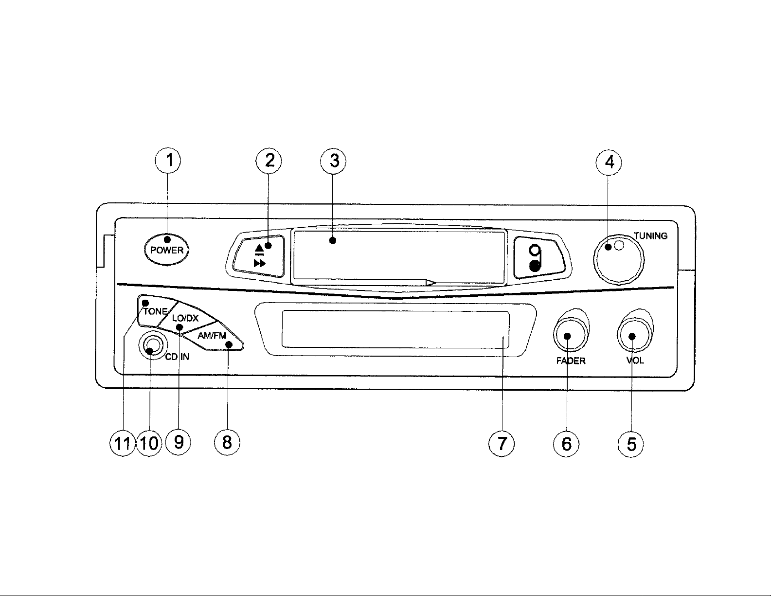
FACEPLATE CONTROLS DIAGRAM
(Figure 1)
2
Page 3

CONTROL DESCRIPTION (see figure 1)
1. POWER BUTTON
Press to turn the unit ON or OFF.
2. EJECT BUTTON
Press this button in half way to fast-forward the tape, and fully in to eject the tape.
3. TAPE DOOR
4. TUNING KNOB
Rotate the knob to tune the desired broadcast frequency.
5. VOLUME KNOB
Rotate the knob to increase or decrease the volume level.
6. FADER KNOB
Rotate this knob to left or right for desired sound balance from front to rear speakers.
7. DISPLAY
8. AM/FM BUTTON
Press this button to change from AM to FM band.
9. LO/DX BUTTON
Press this button to change between local (LO) and distant (DX) reception. In some cases,
changing the LO/DX setting will allow clearer reception of a desired station.
10. CD IN JACK
Jack is for use with an external program source, such as a portable tape or CD player.
11. TONE BUTTON
Press this button to adjust for high or low tone.
3
Page 4
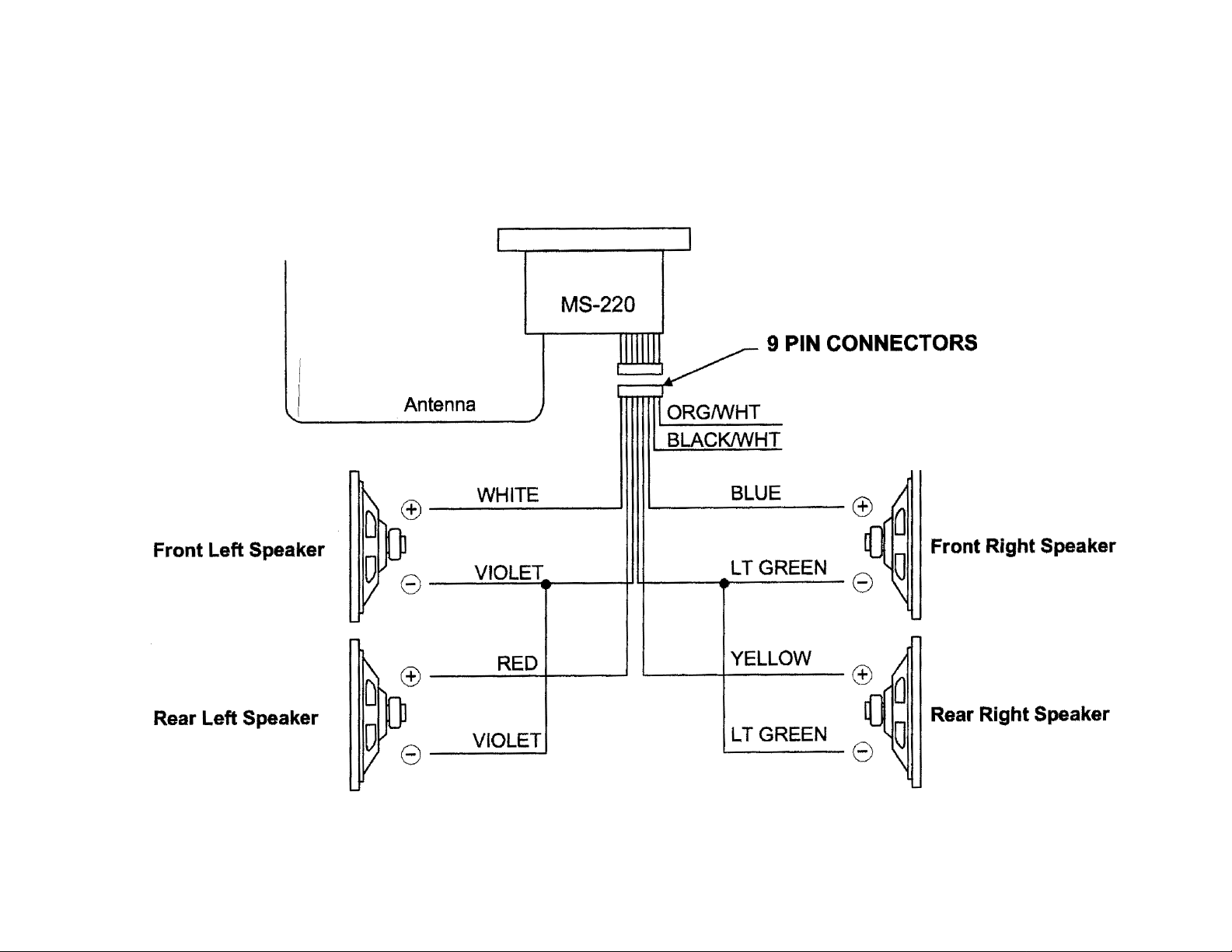
WIRING DIAGRAM
(Figure 2)
TO 12V DC (+) POWER
TO GROUND (CHASSIS OR 12 VDC(-)
TO 12 VOLT DC (+) POWER
TO GROUND (CHASSIS OR 12 DCC(-)
4
Page 5
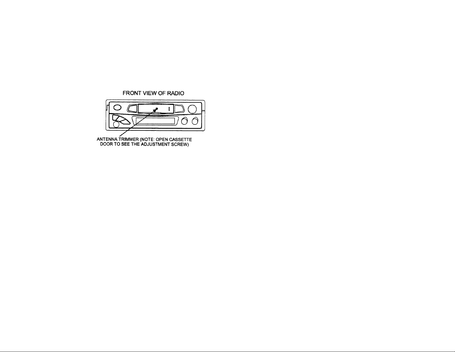
AM ANTENNA TRIMMER ADJUSTMENT
wound inside the take-up spool on the cassette.
The antenna trimmer can be accessed through the small hole behind the cassette door
(see diagram below). Tune to a weak station between 1200 and 1400 KHz AM. (If you cannot
find a weak station in this range, tune to any other strong station, and adjust tuning slightly off
station). Adjust trimmer for maximum volume.
CARE & MAINTENANCE
Cassette
Always check that the tape is tightly
If the tape is loose, wind it with a six-sided
pencil. Never use C-120 (120 minute) cassettes
in this player. Never use cassette player when
vehicle temperature is near or below freezing.
SPECIFICATIONS
Size: 7” (W) x 2” (H) x 6-5/8” (D)
178mm x 50mm x 150mm
Operating Voltage: 12 VDC, Negative Ground
Output Power: 50 Watts Max. Stereo Power
Output Wiring: Floating Ground type
designed for 4 speaker use.
May also be used with 2
speakers.
Output Impedance: Compatible with 4 or 8 Ohm
speakers
Tuning Range: (AM) 530-1710KHz
(FM) 88-108MHz
Sensitivity: (AM) less than 25uV
(FM) less than 5uV
FM Stereo Separation: More than 23dB
Frequency Response: 50-10000Hz
Wow & Flutter: Less than 0.3%
Cleaning of tape Head & Capstan
Since tapes contain oxides, you will find a
black residue builds up on the tape head and
drive capstan (inside cassette door). These
residues should be cleaned after 50-100 hours
of accumulated tape operation. You can use a
cassette cleaning cartridge available where ever
stereos are sold.
De-Magnetizing
The movement of the magnetic tape head
and metal parts cause a magnetic field to
develop. We recommend you have the tape
player demagnetized at least twice annually.
You can purchase an inexpensive tape head
demagnetizing tool to do this yourself.
5
Page 6

TROUBLESHOOTING CHART
AM/FM RADIOS
Symptom Cause Possible Solution
No Power No 12VDC Check circuit fuse at source
Check in-line fuse on power lead
Power lead disconnected
Ground connection disconnected
Power indicated; No audio
output or very distorted sound
No 12VDC to memory lead
(electronically tuned units only)
Speaker Output shorted Check for shorting of speaker
Speaker out cross channeled Check for proper speaker wiring.
6
Circuit fuse at source
In-line memory lead fuse
leads to ground
Note: Radios have a sticker on
them explaining wiring color
code.
Page 7

Only one channel (right or left
side)
Radio Balance Check radio function
Speaker Disconnected Check speaker connection at
radio and/or speaker
Speaker lead shorted or
grounded
Check speaker wiring continuity
to ground w/tester or meter
Popping in one or both channels Speaker wiring shorted or
positive lead grounded
Speaker terminals grounded or
shorted
No AM Reception
Antenna disconnected Connect antenna
Antenna mast grounded or
shorted
Antenna center lead broken Check antenna or substitute with
Note: Antenna leads can be tested with continuity or multi-tester.
Some may have electronic component (capacitor) built in which will
not allow it to be tested.
Leads from speaker cone to
terminal touching metal basket
or speaker
Check antenna or substitute with
antenna known to be good
antenna known to be good
7
Page 8

APPLICATION NOTES
AM/FM radio. The best way to insure good
AM reception is over 100
AM/FM RECEPTION
Some boats have more than one
reception is to supply a separate antenna for
each radio. Other options available to supply
adequate AM/FM reception to these radios
are listed below, along with some general
information in regards to radio reception.
“Y” ADAPTERS
The “Y” adapters used to connect one
antenna to two radios will only provide AM
reception to one of the radios and will
compromise both AM and FM reception.
AMPLIFIED AM/FM ANTENNA
A popular second antenna that can be used is
our AB-100 amplified AM/FM antenna. It is small
and has a retractable mast that can be mounted
vertically or horizontally. This antenna provides
good FM reception, but the AM reception will be
compromised to some degree because of the length
of the mast.
MAST LENGTH
AM/FM antennas compromise AM reception
by design. The optimum mast length for FM is
approximately 30 inches which is standard for most
automotive antennas. The optimum mast length for
inches which is not
practical for mobile applications.
8
Page 9

Special circuitry in electronic tuned radios
with electronic tuned radios.
was once considered acceptable.
or AM trimmers in mechanically tuned radios,
make up for some of this difference in optimum
mast length for AM reception.
ANTENNA CABLE
Increasing the antenna lead cable length
(adding extensions) will reduce sensitivity of AM
GROUND PLANES
Ground planes are also important when
considering antenna performance. Most
automotive antennas are designed to be
mounted on the metal body of the vehicle.
The metal body reflects the signal
interference generated by the vehicle’s electrical
system while it also provides the ground for the
antenna lead shield. All this is necessary in order
to maintain a good signal, especially AM.
FM RECEPTION
FM reception can be received with a very
limited antenna and strong local FM stations can
be received without an antenna, depending on the
circumstances.
CONCLUSION
AM/FM reception is subject to the choice of
an antenna and it’s application. There can also be
a variety of methods used to supply signal to both
primary and secondary radios, but AM
performance is the ultimate “test”.
It appears that consumers or end users are
becoming much more critical when it comes to
acceptable antenna performance. It may be
necessary for manufacturers to re-evaluate what
9
Page 10

APPLICATION NOTES
A large number of our products are designed for
Voltage
where these products will perform unacceptably
This note will discuss DC Power sources and how
they relate to 12 volt DC video products.
DC (Direct Current) Power
12 volt DC applications. The power is supplied by
a variety of sources i.e., the battery, converters,
ignition systems and solar power.
General Specifications
Our general specification for the voltage range of
operation is 10 to 16 volts DC. TV’s and VCP’s
(video cassette players) require slightly more than
10 volts to function properly. Normally this 10.5 to
11 voltage requirement does not create a problem,
but keep in mind the following points:
The voltage of a fully charged battery (engine not
running) is approximately 12.5 VDC. Once a load
(items being powered represent the “load”) is
applied, the voltage will drop. How much the
voltage is reduced will depend on the following:
1. Current draw (amount of amperage); the
higher the draw the greater the voltage
will drop.
2. This size and length of the conductor
(wire) supplying power.
Operating these video products without the
engine running will drain the battery to the point
in a short period of time.
10
Page 11

Converters
when the battery is removed or disconnected the
Ignition Systems
Many boats incorporate converters as a
source of 12VDC when connected to shore
power (110-120 VAC). Some converters put out
a very clean DC supply where others may have
a considerable amount of AC ripple under
maximum load.
This AC ripple is filtered by the boat
battery when connected into the circuit, but
amount of AC ripple can create major problems
for audio and video products. Noise may result
and the line fuse may fail.
Unwanted noise generated from the
ignition systems used to be a big problem.
However, with more sophisticated filtering
circuits designed into audio/video products,
these problems are not as wide spread.
Changes in wire harnessing also has
contributed to the decline of application
problems. Use the same ground point for all
related products. This will greatly reduce the
potential for unwanted noise.
Audiovox Specialized Applications, LLC
23319 Cooper Drive
Elkhart, IN 46514
Phone: (219) 264-3135
FAX: (219) 264-3007
OEM web site: www.asaelectronics.com
11
Page 12

ACCESSORY LIST
Description
AVT-988 9” Color Television with Remote (12V) AVT988 $320.00
AVT-597 5” Color Television with Remote (12V) AVT597 $320.00
AVT-1498 13” Color Television with Remote (12V) AVT1498 $350.00
AVP-7000 Video Cassette Player (12V) AVP7000 $270.00
BPA-501-12 4 Amp Adapter for use with AVT-988 9” and AVT-1498 13”
Televisions
AC2A- 2 Amp Adapter for use with AVT-597 5” TV and AVP-7000 Video
Cassette Player
Unified Remote Control 0892325 $45.00
VAC-21- 12 Volt Corded Vacuum VAC21 $35.00
AVF-1 12 Volt Rechargeable Flashlight AVF1 $25.00
HP-175 Headphones with Pivoting Ear Cup HP175 $11.75
HP-275 Headphones with Volume Control on Cord HP275 $16.00
HP-375 Studio Quality Headphones HP375 $14.00
Unlike household electronics, all of our products have been specifically designed and tested for the
mobile environment and are only available through ASA. To order any of these products, please
contact Audiovox Specialized Applications at www.asaelectronics.com or 800-688-3135.
Part Number Price
0891412 $45.00
0891436 $35.00
*Prices subject to change
12
Page 13

 Loading...