

Page 1
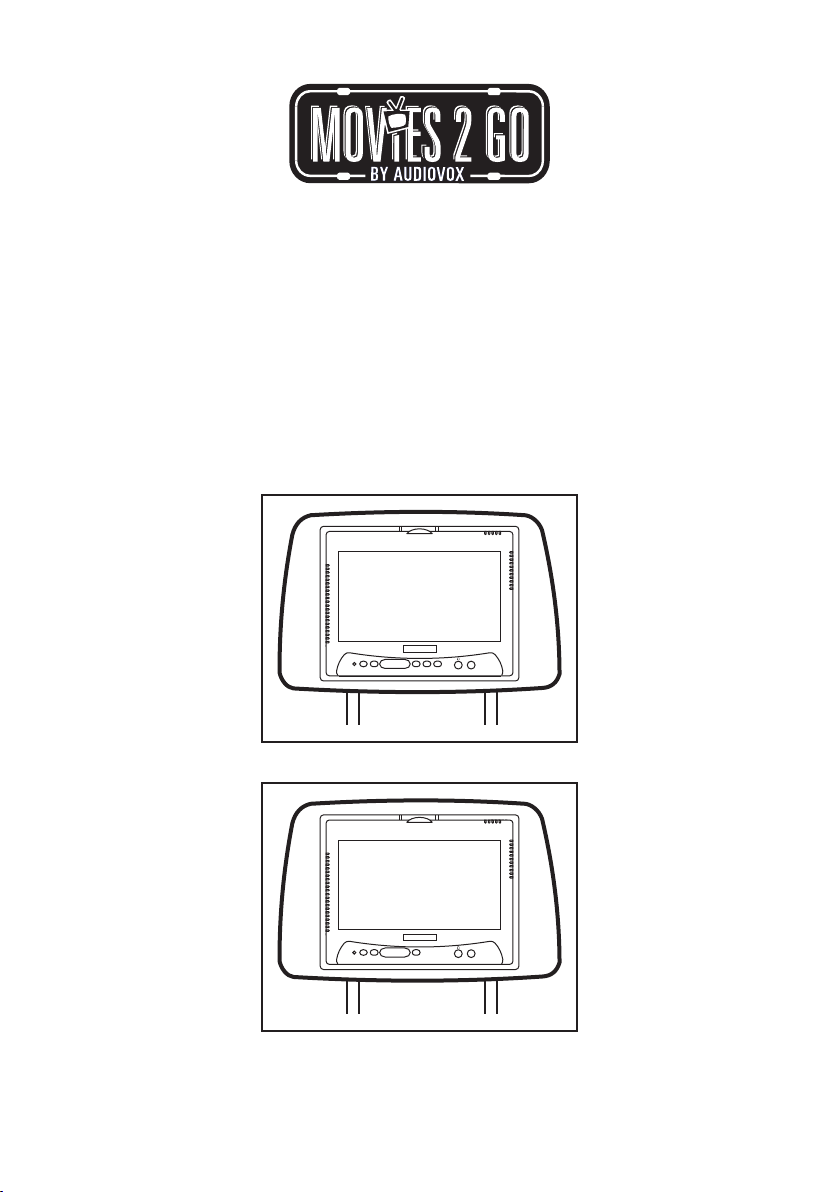
MMD7HRB
MMD7HRT
MMD7HRG
Two Specific Vehicle Headrests
With 7" LCD Monitors and Built-In
DVD Player for Rear Seat Entertainment
SOURCE AUXPOWER
SCREEN
PLAY STOP
MODE
SOURCE AUXPOWER
SCREEN
MODE
Installation Guide
128-8658
Page 2
IMPORTANT
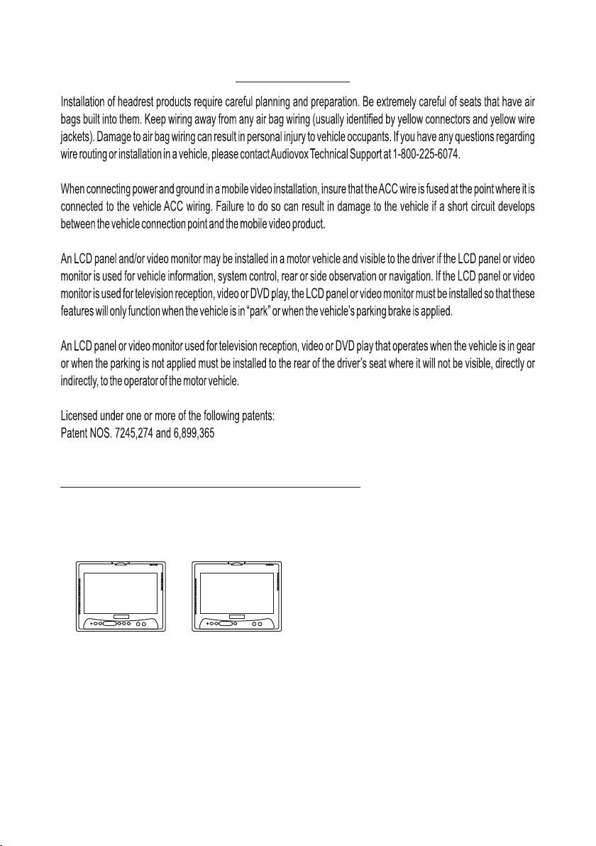
MATERIALS INCLUDED IN THIS PACKAGE:
1) MMD7HRB, MMD7HRT, MMD7HRG System Monitor
MMD7HRM Master Monitor with DVD Player (1pc)
MMD7HRS Satellite Monitor (1pc)
MMD7HRSMMD7HRM
SOURCE AUXPOWER
SCREEN
PLAY STOP
MODE
SOURCE AUXPOWER
SCREEN
MODE
Master Monitor (M1) Satellite Monitor (SM)
2
Page 3
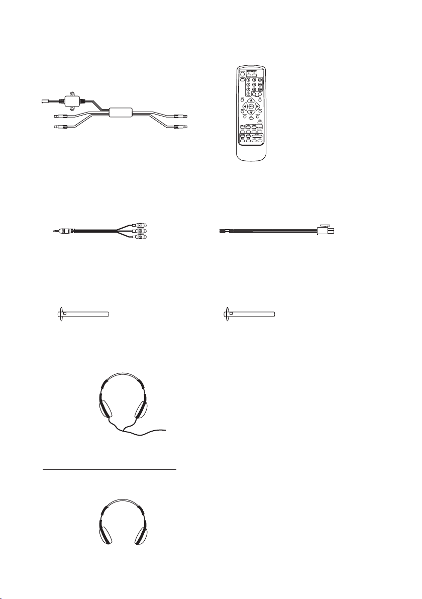
2) Interface Harness
(P/N 136-3977) - (1pc)
2) Universal Remote Control
(P/N 136-3785) – (1pc)
3) AV Adapter Cable
(P/N 112B3227) - (2pc)
5) Post Tube 12MM
(P/N 100-2508) - (2pcs)
7) Wired Headphone (P/N 136-3758) - (2pcs)
OPTIONAL ACCESSORIES:
8) Infrared Channel Wireless Headphones
4) 2 Pin DC Power Cable
(P/N 112-3667) - (1pc)
6) Post Tube 14MM
(P/N 100-2509) - (2pcs)
3
Page 4
MMD7HRB, MMD7HRT, MMD7HRG SYSTEM OVERVIEW
1) The SYSTEM is a versatile audio / video system with built-in DVD player (MMD7HRM only)
which includes two monitors, that can accept an Audio / Video input and independent AUX
input. A separate audio output is provided for connecting an optional FM Modulator to the
vehicle's radio.
2) The M1 Monitor (MMD7HRM) is comprised of a 7" TFT LCD monitor with built-in DVD player
that allows the user to playback DVD, and the AUX source. The M1 monitor ha s a bu i l t - i n
infrared audio transmitter (CH A) for use with the optional two-channel wireless headphones
(CH A).
3) The SM Monitor (MMD7HRS) is comprised of a 7" TFT LCD monitor that allows the user to
select display from the DVD source in M1 (AV1) or AUX source. The SM monitor has a built-in
infrared audio transmitter (CH B) for use with the optional two channel wireless headphones
(CH B).
4) The monitors will show all of the functions with the comprehensive OSD.
5) The optional two-channel wireless Headphone sets have an A-B switch that allow the users to
select the audio from either M1 (MMD7HRM, CH A) or SM (MMD7HRS, CH B).
6) Using different IR codes, the M1 Monitor will only respond to the remote control unit when the
Monitor Select (M1) button on remote control is pressed. The SM Monitor will only respond to
the Remote Control unit when the Monitor Select (M2) button on remote control is pressed.
7) The wired headphones allow the user to listen to audio from the system.
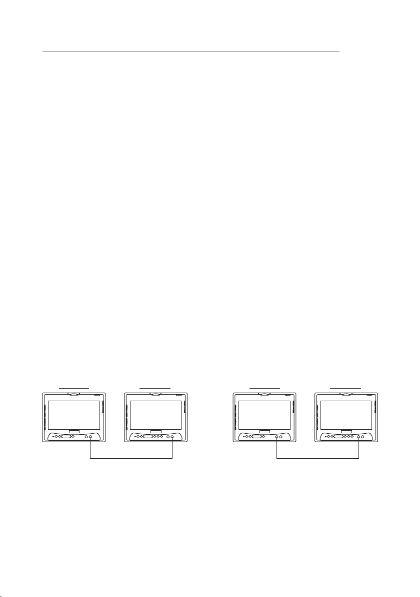
8) The M1 (MMD7HRM) and SM (MMD7HRS) Monitor will accept an audio / video input through
the 1/8” jack located on the front of the unit. The audio / video device could be a video game
system, video camera, or other input device.
MMD7HRS MMD7HRM
SOURCE AUXPOWER
SCREEN
MODE
SOURCE AUXPOWER
SCREEN
PLAY STOP
MODE
AUX IN
MMD7HRS MMD7HRM
SOURCE AUXPOWER
SCREEN
MODE
HEADPHONE
JACK
SOURCE AUXPOWER
SCREEN
PLAY STOP
MODE
4
Page 5

9) Pivot the screen until a comfortable viewing angle reached. The internal lock limits the
screen to a maximum adjustment of 30 degrees from closed position, the headrest itself
can be tilted forward to help achieve a comfortable viewing position.
Inner Ring
Internal Lock
Closed Position
10) Insert disc
Disc Label
Insert disc
MMD7HRM Monitor only.
11) Eject disc
MMD7HRM Monitor only.
30 degrees
Eject disc
5
Page 6

Headrest Installation Description
Choose the headrest cover color to best match your vehicle interior.
SOURCE AUXPOWER
SCREEN
MODE
Monitor Unit
SOURCE AUXPOWER
SCREEN
MODE
MMD7HRS
(Satellite Monitor)
SOURCE AUXPOWER
SCREEN
PLAY STOP
MODE
SOURCE AUXPOWER
SCREEN
PLAY STOP
MODE
MMD7HRM
(Master Monitor)
HEADREST SEMI - ASSEMBLE WITH UNIT
MMD7HRS Monitor
(Satellite Monitor / SM)
1 2
SOURCE AUXPOWER
SCREEN
MODE
SOURCE AUXPOWER
SCREEN
PLAY STOP
MODE
MMD7HRM Monitor
(Master Monitor / M1)
Use a screwdriver to loosen the screw
from the inner-bracket of the headrest.
Push the headrest support inwards or
pull them outward adjust the distance.
6
Page 7

3
Use a screwdriver to tighten the screw
after headrest support have been
adjusted.
4
5
6
SOURCE AUXPOWER
SCREEN
MODE
Adjust match your vehicle
seatback dimension
7
Page 8

VEHICLE PREPARATION:
1) Read the manuals and get familiar with the electrical requirements and
connections.
2) Prepare the vehicle by removing any interior trim necessary to gain access to the
vehicle's wiring as well as all areas where interconnecting wire harnesses will be
located. (Refer to the Installation Procedure). The mounting method, and the
location will vary from vehicle to vehicle, so this manual will only focus for the
installation of the UNIT Master and Satellite Monitors in the supplied configuration.
The best location for the UNIT components is:
a. Monitors: (NOTE: The MMD7HRM Monitor should be installed where the
passenger usually sits behind the front passenger seat.
b. Audio Interface Box: Under either seat where monitors are located.
3) Locate an accessory power source (+12VDC present when the ignition key is in
the accessory and run positions. 0VDC should be present when the ignition key
is in the OFF position), and a good ground. Generally, these wires can be
located at the ignition switch or fusebox.
(NOTE: Ensure that the switched power is fused at the source. Failure to do so
may result in vehicle wiring damage.)
4) Run the wiring harnesses throughout the vehicle as necessary. (Refer to the
Wiring Diagrams on page 10, as well as the wiring instructions for the individual
components and accessory options being installed). Be sure, that all the wiring
is protected from sharp edges and is routed in such a manner that it will not be
pinched, when it is fully installed. Be sure to leave enough slack in the wiring at
each component to allow sufficient working room. Be sure to leave enough
slack in the monitor cables to allow the headrest to move up or down, and the
seat to move backward and forward.
5) Remove all the components from their packaging and then place them in the
vehicle at their respective locations.
6) Install the Headrests:
a. Remove vehicle's original Headrests. Measure the distance between the
posts and adjust the new Headrests to same dimension.
b. Place the appropriate headrest support tube into the support tube hole. (If
needed)
c. Hold the UNIT Headrest above the seat and insert the two cables into the
headrest support tube holes. Make sure that the headrest is in the correct
position (Display facing the rear).
8
Page 9

7) Connect all the components together (electrically) and verify proper operation of
all the system functions.
a. The headrest DIN cables and the Interface Harness DIN cables are color
coded. Connect each headrest cable to the correct color cable on the Audio
interface harness. In some vehicles it will be necessary to use the supplied DIN
extension cables to reach from under one seat to the other seat. The DIN
extension cables can be used for either the MMD7HRM or MMD7HRS
monitors. The extension cables are labeled with color coded Green/Red and
Blue/Yellow. When connecting the extension cables, ensure that the
Green/Red extension cable is used with the Master monitor cable and the
Blue/Yellow extension cable is used with the Satellite monitor cable.
b. Connect the DC power jack.
8) Verify proper operation of the system.
9) Make sure that no wiring is pinched, or connected improperly during the final
installation.
9
Page 10

MMD7HRPKG WIRING DIAGRAM
MMD7HRS Monitor
Satellite Monitor
SOURCE AUXPOWER
SCREEN
MODE
DIN Extension
Cables
(Optional)
MMD7HRM Monitor
Master Monitor
SOURCE AUXPOWER
SCREEN
PLAY STOP
MODE
BLUE
YELLOW
GREEN
RED
Interface
Harness
DIN Extension Cables
10
Page 11

Page 12

www.mobile.audiovox.com
© 2008 Audiovox Electronics Corp., Hauppauge, NY 11788
128-8658
 Loading...