

Page 1
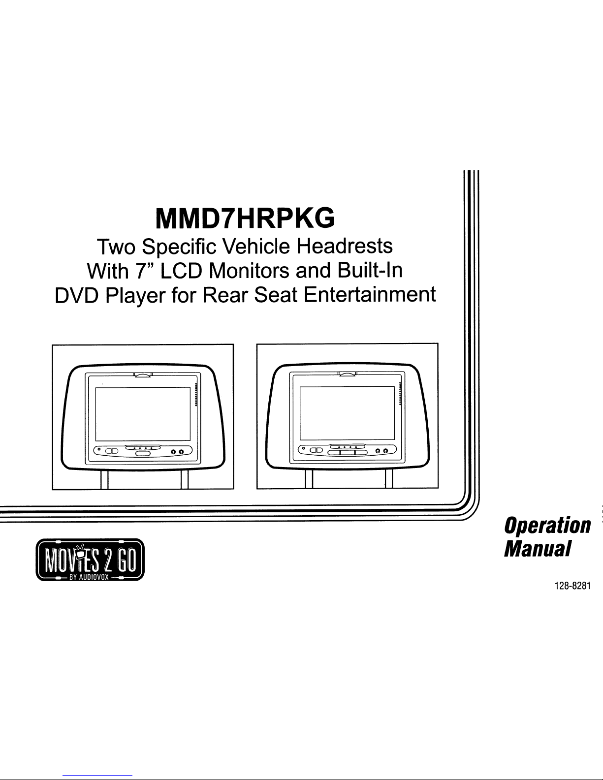
MMD7HRPKG
Two Specific Vehicle Headrests
With
7"
LCD Monitors and Built-In
DVD Player for Rear Seat Entertainment
(
,
e=
00
c
"0"
::>
o
o:=J
\...
~
II II
(
~
00
c...
.:::=>
o
o:=J
( I I )
\...
..J
II II
..
Operation
Manual
128-8281
Page 2

IMPORTANT
Installationofheadrest
products
require
careful
planning
and
preparation.Beextremely
carefulofseats
that
have
airbags
built
into
them.
Keep
wiring
away
from
any
air
bag
wiring
(usually
identifiedbyyellow
connectors
and
yellow
wire
jackets).
Damagetoair
bag
wiring
can
resultinpersonal
injurytovehicle
occupants.Ifyou
have
any
questions
regarding
wire
routingorinstallationina
vehicle,
please
contact
Audiovox
Technical
Supportat1-800-225-6074.
When
connecting
power
and
groundina
mobile
video
installation,
insure
that
the
ACC
wireisfusedatthe
point
whereitis
connectedtothe
vehicle
ACC
wiring.
Failuretodosocan
resultindamagetothe
vehicleifa
short
circuit
develops
between
the
vehicle
connection
point
and
the
mobile
video
product.
An
LCD
panel
and/or
video
monitor
maybeinstalledina
motor
vehicle
and
visibletothe
driverifthe
LCD
panelorvideo
monitorisused
for
vehicle
information,
system
control,
rearorside
observationornavigation.Ifthe
LCD
panelorvideo
monitorisused
for
television
reception,
videoorDVD
play,
the
LCD
panelorvideo
monitor
mustbeinstalledsothat
these
features
will
only
function
when
the
vehicleisin
"park"orwhen
the
vehicle's
parking
brakeisapplied.
An
LCD
panelorvideo
monitor
used
for
television
reception,
videoorDVD
play
that
operates
when
the
vehicleisin
gear
or
when
the
parkingisnot
applied
mustbeinstalledtothe
rearofthe
driver's
seat
whereitwill
notbevisible,
directly
or
indirectly,tothe
operatorofthe
motor
vehicle.
Licensed
under
oneormoreofthe
following
patents:
Patent
NOS.
7245,274
and
6,899,365
Page 3
MMD7HRPKG
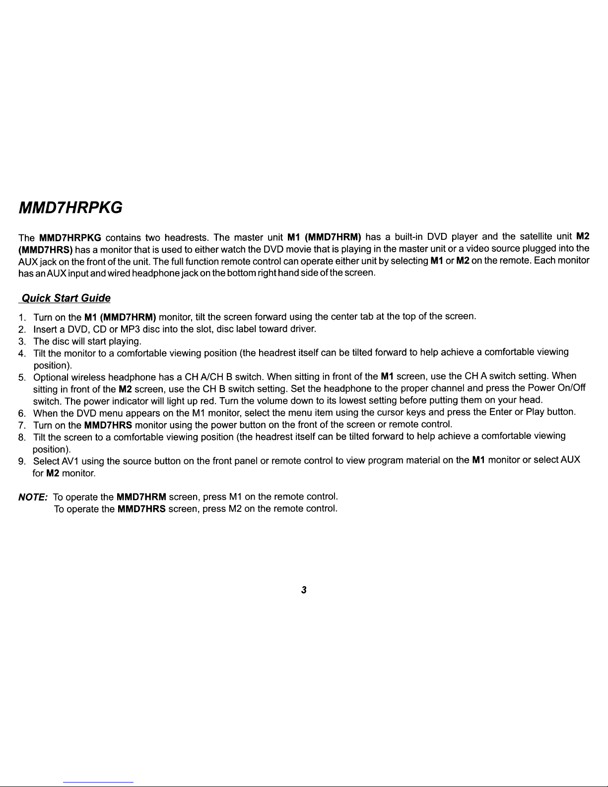
The MMD7HRPKG contains two headrests. The master unit
M1
(MMD7HRM) has a built-in DVD player and the satellite unit M2
(MMD7HRS) has a monitorthat is used to either watch the DVD moviethat is playinginthe master unit ora video source plugged into the
AUXjackon the frontofthe unit. The full function remote control can operate eitherunit by selecting
M1orM2 on the remote. Each monitor
hasanAUX inputand wired headphone jackon the bottom righthand sideofthe screen.
~uick
Start Guide
1.
Turn on theM1(MMD7HRM) monitor, tilt the screen forward using the center tab at the topofthe screen.
2.
Insert a DVD,
CDorMP3 disc into the slot, disc label toward driver.
3.
The disc will start playing.
4. Tilt the monitor to a comfortable viewing position (the headrest itself can be tilted forward to help achieve a comfortable viewing
position).
5.
Optional wireless headphone has a CH A/CH B switch. When sittinginfrontoftheM1screen, use the CH A switch setting. When
sittinginfront of the M2 screen, use the
CH
B switch setting. Set the headphone to the proper channel and press the Power On/Off
switch. The power indicator will light up red. Turn the volume down to its lowest setting before putting themonyour head.
6.
When the DVD menu appears on theM1monitor, select the menu item using the cursor keys and press the Enter or Play button.
7.
Turn on the MMD7HRS monitor using the power button on the frontofthe screenorremote control.
8.
Tilt the screen to a comfortable viewing position (the headrest itself can be tilted forward to help achieve a comfortable viewing
position).
9.
Select
AV1
using the source button on the front panel or remote control to view program material on theM1monitor or select AUX
for M2 monitor.
NOTE:
To
operate the MMD7HRM screen, pressM1on the remote control.
To
operate the MMD7HRS screen, press M2 on the remote control.
3
Page 4
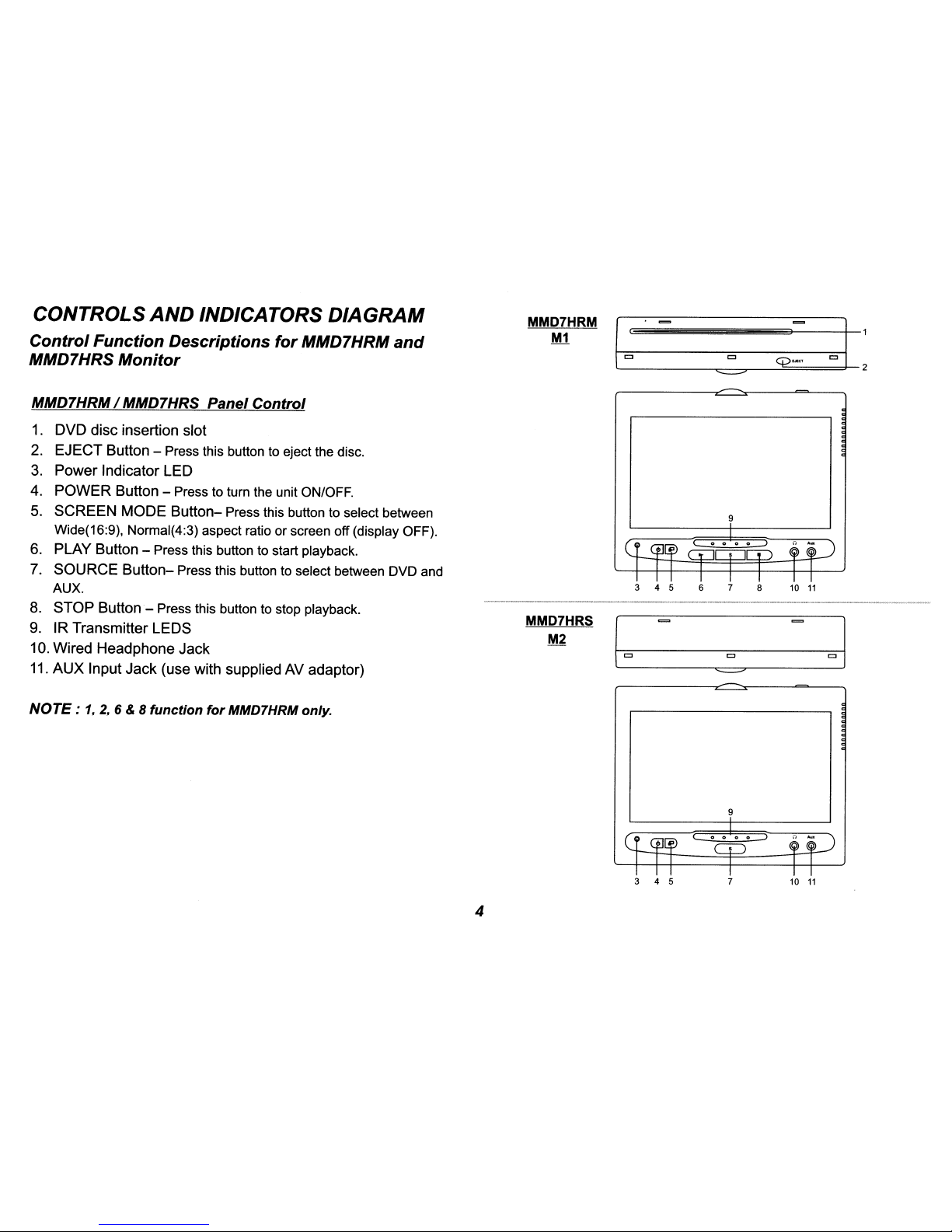
CONTROLS
AND
INDICATORS
DIAGRAM
MMD7HRM
I~
==-
ot:
M1
J
Control
Function
Descriptions
for
MMD7HRM
and
MMD7HRS
Monitor
c
q>
...
"
~
MMD7HRM/ MMD7HRS Panel
Control
1.
DVD disc insertion slot
2.
EJECT Button - Press this button to eject the disc.
3.
Power IndicatorLED
4. POWER Button -
Press to turn the unit ON/OFF.
5.
SCREEN MODE
Button-
Press this button to select between
9
Wide(16:9), Normal(4:3) aspect ratioorscreen off (display OFF).
6. PLAY Button - Press this button to start playback.
7. SOURCE
Button-
Press this button to select between DVD and
AUX.
3 4 5 6
7
8
10
11
-_
..
_----~.
-_._"""="""~
....
...
"'_._c_
.........z,......
___
.....
8. STOP
Button-
Press this button to stop playback.
9. IR Transmitter LEOS
MMD7HRS
(0
01
M2
10. Wired Headphone Jack
c
11.
AUX
Input Jack (use with supplied AV adaptor)
~
NOTE:
1,2,6 & 8
function
for
MMD7HRM only.
9
4
3 4 5 7 10
11
Page 5

MMD7HRPKG SYSTEM OVERVIEW
1) The MMD7HRPKG SYSTEM is a versatile audio / video system with built-in DVD player (MMD7HRM only) which includes two monitors, that can
accept an Audio / Video input and independent AUX input. A separate audio output
is
provided for connecting an optionalFMModulator to the
vehicle's radio.
2) The
M1
Monitor (MMD7HRM)iscomprisedofa 7" TFT LCD monitor with built-in DVD player that allows the user to select from the DVD, and the
AUX source. The
M1
monitor has a built-in infrared audio transmitter (CH A) for use with the optional two-channel wireless headphones (CH A).
3) The M2 Monitor (MMD7HRS)
is
comprisedofa 7" TFT LCD monitor that allows the user to select from the DVD sourceinM1
(AV1) orAUX source.
The
M2
monitor has a built-in infrared audio transmitter (CH B) for use with the optional two channel wireless headphones (CH B).
4) The monitors will show all
of
the functions with the comprehensive OSD.
5) The optional two-channel wireless Headphone sets have an A-B switch that allow the user to select the audio from either
M1
(MMD7HRM,CHA)
or M2 (MMD7HRS,CH
B).
6) Using differentIRcodes, theM1Monitor will only respond to the remote control unit when the Monitor Select (M1) button on remote control
is
pressed. TheM2Monitor will only respond to the Remote Control unit when the Monitor Select (M2) button on remote controlispressed.
7) The wired headphones allow the user to listen to audio from the system.
8) The
M1
(MMD7HRM) and M2 (MMD7HRS) Monitor will accept an audio / video input through the 1/8" jack located on the front of the unit. The
audio / video device could
be
a video game system, video camera, or other input device.
MMD7HRS
MMD7HRM
MMD7HRS MMD7HRM
CJ
CJ
r.....
CD"""""" 0 )
r.....
CD
o )
AUXIN
5
CJ
CJ
<:CD
~
OJ
r....·CD~
'v
HEADPHONE
JACK
Page 6
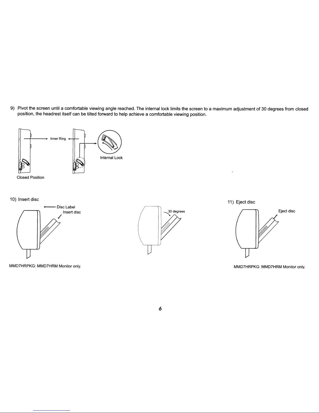
9) Pivot the screen until a comfortable viewing angle reached. The internal lock limits the screen to a maximum adjustmentof30 degrees from closed
position, the headrest itself can
be
tilted forward to help achieve a comfortable viewing position.
Inner Ring
Closed Position
10) Insert disc
-Disc
Label
Insert disc
/
MMD7HRPKG: MMD7HRM Monitor only.
Internal Lock
6
11) Eject disc
Eject disc
MMD7HRPKG: MMD7HRM Monitor only.
Page 7

REMOTECONTROLOPERATION
-+--1-+--
14
L.....----I-+--
13
27
1
26
25
2
3
24
23
4
22
5
21
6
20
7
19
8
18
9
17
10
16
11
15
12
CR2025
Initial Use
When purchased the remote control has a battery installed with
a Pull
Tab
to prevent battery discharge. Remove the Pull
Tab
before attempting to use the remote.
Battery Replacement
1.
Remove the battery holder.
2.
Insert the battery into the battery holder and insert the
battery holder into the remote. Be sure to observe the correct
polarity.
3.
Align the battery holder with the remote control and push
until the holder clicks.
7
Page 8

*
REMOTE CONTROL FUNCTION DESCRIPTIONS
Function/controlisavailableonthe unit and remote control.
** Function/control
is
not availableonthis model.
NOTE:
To
control the individual units (MMD7HRM Monitor / MMD7HRS Monitor) press eitherM1orM2before pressing any other
button.
For example, to turn MMD7HRM Monitor ON, press
M1
and then the power button.
1.
POWER Button* - Press this button to turn MMD7HRM or MMD7HRS Monitoron/ off.
2.
MUTE Button - Press this button to mute the audio. Pressing the button again restores the audio to the previously set level.
3.
ENTER Button - Used to implement a selected setting.
4.
CURSOR
(.A.
.......
~)
Button - Use these buttons to navigate the menu selectionsonthe screen.
5.
PREY
(~)
Button - Press to return to the previous chapter or track.
6.
SCAN BACKWARD
(~)
Button - Press to searchina backward direction. Press repeatedly to change the search speed from
2,
4,8
and 20 times the normal speed.
7.
PLAY
(~)
Button* - Press to activate the play mode while a discisloadedinthe disc compartment.
8.
SETUP Button - Press to display the Setup Menu which allows the user to change the DVD player options such as TV DISPLAY,
OSD LANGUAGE, PARENTAL CONTROL etc.
Refer to the settings and Adjustments section for more information.
9.
REPEAT Button - Allows the user to repeat a selected Title, Chapter or Trackofa DVD, CD or MP3.
8
Page 9

10. ZOOM
Button
- Press this button to enlarge the picture when playing a DVD disc.
Press ZOOM
button
DVD
player
perform
Once Enlarge the picture 1 timesofthe original size
Twice Enlarge the picture 2 times
of
the original size
3 times Enlarge the picture 3 times
of
the original size
4 times Picture
is
returned to original size
11.
IRT ON/OFF Button** - Press this button to turn the selected unit IR Transmitter ON/OFF.
12. NUMBER
Buttons
- Allows the usertoenter the numbers 0 to 9 for selectionofCD tracks, DVD chapters, and password setting.
13.
FM
ON/OFF Button** - Turns
FM
Modulator power ON/OFF.
14. CHANNEL SELECT
Button**
- Selects theFMmodulator Frequency
(Frequency 1:88.3MHz, Frequency 2:88.7MHz, Frequency 3:89.1 MHz, Frequency 4:89.5MHz, Frequency 5:89.9MHz).
15. DISC MENU
Button
- Allows the user to access the DVD (DVD MODE) main menu.
00:00:14
Chapter ./.
~Jitie
__
"'-",_=-!
Chapter _
DVDVIDEO
Title
1/17
Audio
111
IT]
5.1
Ch
Subtitle
Off
Angle
111
16. DISPLAY
Button
- Press to display the current disc information while the discisplaying. Press the cursor (..........~)buttons to
highlight the desired option. For title and chapter selection use the number buttons to enter the desired title or chapter number for
angle, audio, and subtitle. Press the ENTER button repeatedly
to
change the item.
Title
Chapter
Angle
Audio
Subtitle
17. SUBTITLE
Button
- Press to display and select the subtitle languageinDVD mode. Each time you press the button, the subtitle
language changes.
NOTE:
The
type & numberoflanguage for subtitles vary from disctodisc.
9
Page 10

18. AUDIO
Button
- Press to display and select the AUDIO languageinDVD mode. Each time you press the button, the language
changes.
NOTE: The languages for audio vary from disc to disc.
19.
SCAN
FORWARD
(~)
Button
- Press to searchina forward direction. Press repeatedly to change the search speed from 2,4,8
and 20 times the normal speed.
20. STOP
(.)
Button*
- Press to stop playback.
21. PAUSE
(II)
Button
-Allows
the
userto
pausethe playback. Press the Play button toresume normal playback.
22. NEXT (»I)
Button
- Press to skip to the next chapterortrack.
23. PIX
Button
(PICTURE SELECT) - Each time this button is pressed, the on screen picture adjustment displays the "adjustment bar"
for BRIGHTNESS, CONTRAST, COLORorTINT* (*For NTSC only). Once the desired adjustment bar is displayed, use the VOL (+)
I VOL
(-)
button to adjust the setting. The display will automatically turn offifno adjustments are made within 6 seconds,orif
any
other button is pressed.
24.
VOL
(-)
I (+)
Button
- Use this button to decreaseorincrease the volume levelofthe wired headphone jack.Itis
also used to do
picture adjustmentsinpicture select mode.
25.
Monitor
Select
(M1) - Change the remote control code to enable the controlofMMD7HRM Monitor.
26.
Monitor
Select
(M2) - Change the remote control code to enable the controlofMMD7HRS Monitor.
27. SOURCE
Button*
- Press this button to select the available sources. MMD7HRM monitor, sources are DVD &AUX.
MMD7HRS Monitor, sources are
AV1
(DVD from MMD7HRM monitor) & AUX.
10
Page 11
SETTINGS AND ADJUSTMENTS
(M1
ONLY)
The Setup Menu contains features and options that let you customize your DVD player. For example, you can set a language for the onscreen display or prevent DVD playback for children.
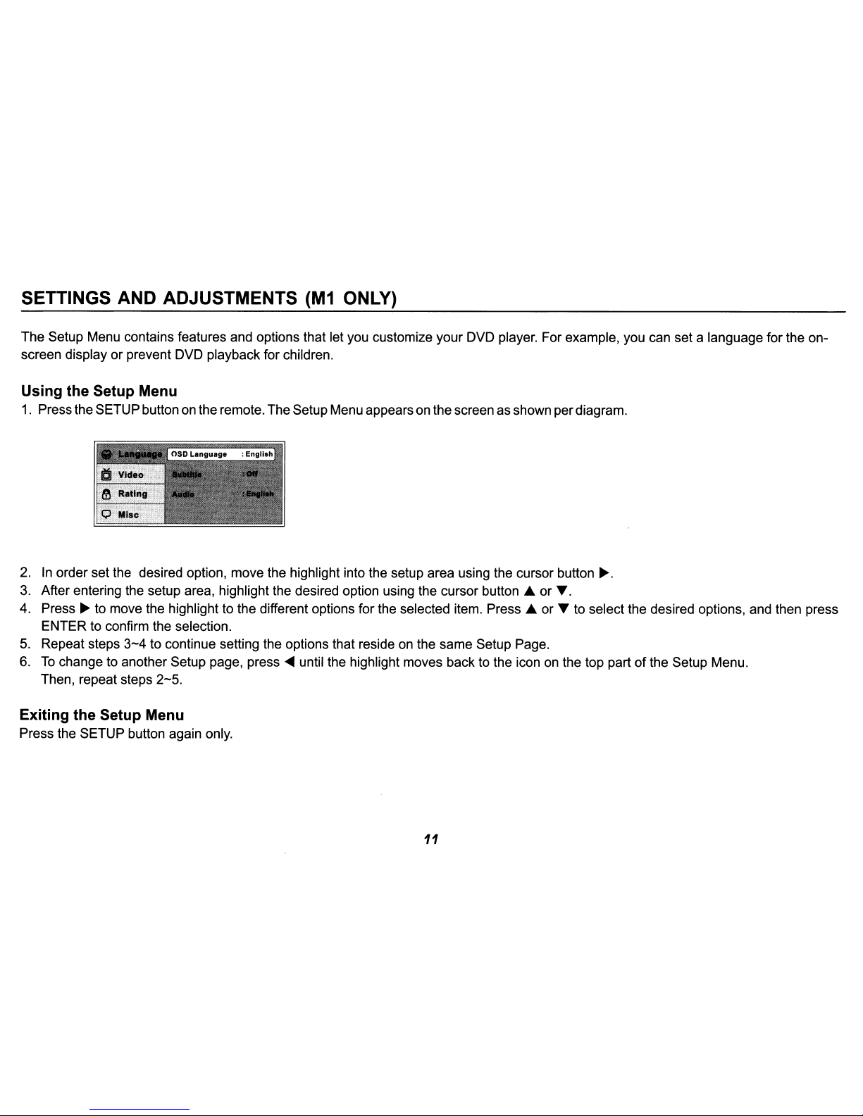
Using the Setup Menu
1.
Pressthe SETUP button on the remote. TheSetupMenu appearsonthe screen as shown perdiagram.
2.Inorder set the desired option, move the highlight into the setup area using the cursor button
~.
3.
After entering the setup area, highlight the desired option using the cursor button .A or
T.
4. Press~to move the highlight to the different options for the selected item. Press .A or T to select the desired options, and then press
ENTER to confirm the selection.
5.
Repeat steps
3-4
to continue setting the options that resideonthe same Setup Page.
6.
To
change to another Setup page, press~until the highlight moves back to the icon on the top partofthe Setup Menu.
Then, repeat steps
2-5.
Exiting the Setup Menu
Press the SETUP button again only.
11
Page 12
LANGUAGE SETUP
Language for On-Screen Display
OSD MENU: The OSD MENU setup allows you to select the language for the on-screen display.
The user can either select English, French, Spanish, German or Italian for the OSD language.
SUBTITLE SETUP
Select "SUBTITLE" using
..
T button, then press
~
button to enter the Submenu. Select the subtitle you
desire using
..
T button, then press "ENTER" to confirm the setting. Press
~
button to return.
Note: The subtitle selection is only available for discs that are recordedinthe above listed languages.Ifthe selected,
language is not available, the playerwill play and display on the screen the original language contained in the disc.
AUDIO SETUP
Select "AUDIO" using
..
T button, then press
~
button to enter the Submenu. Select the audio you
desire using
..
T button, then press "ENTER" to confirm the setting. Press
~
button to return.
Note: The audio selection is only available for discs that are recorded in the above listed languages.Ifthe selected,
language is not available, the player will
play
and display on the screen the original language contained in the disc.
VIDEO SETUP
TV Display
The TV DISPLAY setup allows you to adjust screen setting (aspect ratio).
4:3 This displays the wide picture with black bands
on
the upper and lower portionsofthe screen.
16:9 This displays a wide picture with black bands
on
the upper and lower portionofthe screen.
The bandwidth will vary, depending on the aspect ratio
of
the disc.
12
French
Spanish
German
Italian
English
French
Spanish
German
Italian
Japane.e
Chln..e
Page 13

TV Type
TheTVTYPE setup allows you to select the system to fit to the color systemoftheTVto be connected.
NTSC - Select this type for NTSC TV
PAL - Select this type for PAL TV
Multi - Select this type for multi-system
TV
RATING SETUP
Rating
This item allows you to limit the contentofmovie playback from G to Adult. The lower the value, the more strict the control.
G
PG
PG-13
R
NC-17
Adult
The rating level can only be changed when the displayed lock is open. For first time use, key in the
default password (3308) and press Enter.
To
set a new password, keyina new four-digit password and
press enter.
Note:
The DefaultPasswordis 3308. This
password
is alwayseffectiveevenafteryouhaveselected
your
ownpassword
and
changed
it.Toavoid the possibility
of
othersusing the default
passwordtoset
the parentallevel
and
change the password, you can record this defaultpasswordin anotherarea
and
deleteitfrom
thismanual. Some discs can be limited depending on the age
of
userswhilesomediscscannot.
Mise SETUP
Select "MISC" using
..
T button, then press
~
button to enter the Misc menu. Select the subtitle you
desire using
..
T button, then press "ENTER" to confirm the setting. Press
....
button to return.
13
Page 14

Load Factory
Load Factory allows you to reset all options to factory settings.
* This function will not affect the Rating control settings.
Screen Saver
ON -Screen saver will appear
OFF -Screen saver will not appear
Note:
The
DVD player will enable the Screen Savermodeifthe unit is inactive for approximately 3 minutes.
Playing DVDs
1.
Press the DISPLAY button on the remote control to display the status banner. The banner includes title, chapter, angle, audio, subtitle,
title selection & chapter selection.
2.
Title Selection
Press numeric (0-9) buttons to initiate a changeoftitle selection. Then press ENTER to implement the selection.
3.
Chapter selection
Press numeric (0-9) buttons to initiate a changeofchapter selection. Then press ENTER to implement the selection.
As you toggle through the options, the repeat option changes at that time. The track, for example, repeats once that track has ended. The
selected repeat option loops repeatedly until you turn it off.
14
Page 15

Playing MP3 Discs
MP3 is a format for storing digital audio. An audio CD-quality song can be compressed into the MP3 format with very little lossofquality,
while taking up much less space. CD-R discs that have been encoded
in
MP3 format can be played on your DVD player. The DVD player
plays the songs
in
the order they were burned on to the disc.
When playback
is
started the elapsed timeofthe track that is playing will be displayed.
Selecting Folders and Songs
When a device containing MP3 filesisloadedinthe player, the navigation menu appears automatically.
1.
Press.
or ... to move the highlight to the desired folder (if present)onthe left sideofthe menu and
press OK. The songs
in
the folder will be displayed on the screen.
2.
Press.
or ... to move the highlight to the desired track containing the song and press OK to begin
track playback.
00:00:01
03/13
0 ITRACK02.MP3
Skipping Songs
Use the Next
(~~)
button on the remote control to move to the next song. Use the Previous
(~~)
button to move to the previous song.
Selecting a Play Mode
Filter (For MP3 & JPEG only)
Filter Mode enables
or
disables the displayoffiles contained on the media based on their file extension.
The Filter function applies to the following formats:
Audio - Audio data format (MP3, WMA)
Photo - Photo data format (JPEG)
Video - Video data format (MPEG
I,
][)
15
Page 16

Flat Mode: play the entire disc
This modeisalwayson(default). During the Flat
Mode
all
the data folders with
MP3,
JPEG & movies
will
be
playedinsequence. If the Flat Mode functionisoff,
it will only play the selected folder; other folders are disabled.
Repeat: play repetitively
Repeat function has 4 options: Off, Single, Folder, All. Move cursor to Repeat function and press OK;
Off/Single/Folder/AII are displayed
in
that order. Repeat default is Off;
Off
Single
Folder
All
Turn
off
repeat function
Repeat the song being played until STOP is pressed.
Play all songs
in
a folder repetitively
Play all songs on the disc repetitively
Mode: play mode
The Mode function has 4 options: Normal, Shuffle, Random and Music Intro. Move cursor to the desired Mode function and press OK;
Normal/Shuffie/Random/Music Intro are selected
in
that order. The Mode function default status is Normal.
Normal: Play all songs
in
folder once
Shuffle: Play songs
in
a folderina shuffled order. Each songinthe folder is played only once.
Random: Play songs in a folder in a random order. Each song
in
the folder is played only once.
Music Intra: Play each song
in
orderinthe folder for 10 seconds
Remark-- The purpose
of
the Music Intro function is to provide the user with a sampleofeach song for 10 seconds, thereby making it easy
to select and listen to a favorite song.
16
Page 17

Edit Mode
Program View
Add to Program
Notice: Edit Mode/Program View/Add to program functions are all related and can not be implemented
during play mode
or
any other program function.
Method: Make sure disc playback is off. Move cursor to Edit Mode function and press OK. After Edit Mode
is
selected, open the folder and
select the songs which will
be
compiled. A check mark appears to the left of the selected song; highlight the Addtoprogram function and press
OK. The selected song
is
addedtoa new program and the check mark disappears; move cursor to Program view function and press OK to
browse the songs
in
the program.
In Edit Mode,
if
Add to program function is used, highlight Program view function and press ENTER; the following selections appear:
Edit Mode
Browser View
Clear Program
Method: When Add toprogramfunction is finished, highlightthe Browserview function; the songs in the new
program are displayed.
To
delete a selected song, highlightthe selected song; a check mark appears to the
left
ofthe
selected song. Highlight Clearprogramfunctionand press OK;the song will be deleted.
17
Page 18

DVD Basics
To
get the optimum use outofthe DVD section, make sure you read this section completely.
Regional Coding
Both the DVD player and DVDs are coded by region. These regional codes must matchinorder for the disc to play. If the codes don't
match, the disc won't play. This unit's code is region
1.
Other regional codes cannot be playedinthis unit. The unit will display
"WRONG REGION".
TypesofDiscs your DVD will play
-DVD* disc - DVD discs which contain video.
-Audio discs - Audio CDs contain musical or sound content only.
-MP3 discs - A disc that contains audio files (for example, a CD-R with downloaded MP3 files).
* This system is capable
of
playing most recordable DVD formats. However, due to the variety of disc manufacturers and software,
playback cannot be guaranteed.
Loading and Playing Discs
Before you load a disc, make sure that it is compatible with the player. Insert the disc with the label facing the driver.
Note: the following Discs CANNOT be used with this player:
-MiniDisc
-Laserdisc
-CD-1, CD-ROM, DVD-ROM, Super Audio CD (SACD), DVD Audio, JPEG (KODAK)
To
load and·Play a
Disc
Press the Power button to turn the unit ON. Select DVD mode and insert the disc (Label towards driver) into the disc compartment.
18
Page 19

Audio I Video Inputs and Outputs
Audio Output
The Audio output will provide the Audio signal from the MMD7HRM unit. This output can be connected to your car Audio input or a
wired
FM
Modulator (Audiovox FMM1
DDA)
Source Feature
MMD7HRM Sources: DVD & AUX
DVD - Select DVD to view the internal DVD player.
AUX - SelectAUX to view the source that is connected to the AUX input*
on
the frontofthe unit.
MMD7HRS Sources:
AV1
& AUX
AV1
- Select
AV1
to view the DVD player from the MMD7HRM monitor.
AUX - Select AUX to view the source that is connected to the AUX input* on the front
of
the unit.
*The AUX input requires the use
ofAVadapter cable (1/8-to-RCA) supplied by Audiovox.
19
Page 20

TROUBLESHOOTING
PROBLEM
SOLUTION
IR sensor inoperative
• Verify that the batteries
in
the remote are fresh.
• Verify that the remote sensor eye
is
not obstructed.
• Verify that Master Monitor or Satellite Monitor has been selected correctly.
Disc won't play
• Check the type
of
disc you put into disc tray. This DVD only plays DVDs, audio CDs
and MP3s.
• Both the unit and the disc are coded by region. If the regional codes don't match,
the disc can't be played.
Play starts, but then stops immediately
• The disc is dirty. Clean
it.
• Condensation has formed. Allow player to dry out.
No sound or distorted sound
• Make sure your DVD is connected properly. Make sure all cables are securely
inserted into the appropriate jacks.
• Disc loaded backwards, turn disc around so that the disc label is facing towards
the driver.
OSD Displays "Incorrect Disc Format"
• Disc loaded backwards, turn disc around so that the disc label
is
facing towards
the driver.
20
Page 21

A
CAUTION
1. Keep the monitor clean and dry.
2. Always seek qualified personnel to perform repairs. Never attempt your own repairs.
3.
Do not drop the monitororexpose to strong impacts.
4. Do not expose to direct sunlight for extended periods
of
time.
MONITOR SPECIFICATIONS
1.
Type
TFT
Active Matrix LCD
2. Resolution 1440 (W) x 234 (H)
3.
Pixels
336,960
4.
Back Light
Edge Light Tube
5.
Power Source +12 VDC
6. Power Consumption
26W
7. Operating Temperature
32°F - 125°F (-O°C - +52°C)
8. Storage Temperature
-22°F - 150°F (-30°C - +70°C)
9. Video Display System
NTSC/PAL
10. Backlight life
10,000 hours
11.
HeadphoneAudio Output
0.03W @ 32 ohm
21
Page 22

12 MONTH LIMITED WARRANTY
-
Applies to Movies
To
Go Mobile Video Products
AUDIOVOX ELECTRONICS CORP. (the Company) warrants to the original retail purchaserofthis product that should this product or
any part thereof, undernormal use and conditions, be proven defective in material
or
workmanship within 12 monthsfrom the date
of
original purchase, such defect(s)will be repairedorreplaced with reconditioned product(atthe Company's option) without charge for
partsand repairlabor.
Agame
controller, if supplied, issimilarlywarrantedforninety(90)days.
To
obtain repairorreplacement within the termsofthis Warranty, the product is to be delivered with proofofwarranty coverage (e.g.
dated bill
of
sale), specificationofdefect(s), transportation prepaid, totheCompanyatthe addressshown below.
This Warranty does not extend to the elimination
of
externally generated staticornoise, to correctionofantenna problems, to costs
incurredforinstallation, removal
or
reinstallationofthe product,orto damage to digital memory/mediadevices, gamingdevices, discs,
speakers, accessories, orvehicle electrical systems.
This Warranty does not apply to any product
or
part thereof which, in the opinionofthe Company, has sufferedorbeen damaged
through alteration, improper installation, mishandling, misuse, neglect, accident, or by removal
or
defacementofthe factory serial
number/barcode label(s). THE EXTENT OFTHE COMPANY'S LIABILITY UNDERTHIS WARRANTY
IS
LIMITED TO THE REPAIR
OR
REPLACEMENT PROVIDED ABOVE AND,INNO EVENT, SHALL THE COMPANY'S LIABILITY EXCEED THE PURCHASE
PRICE PAID BYPURCHASER FORTHE PRODUCT.
This Warranty is in lieu
of
all other express warrantiesorliabilities.
ANY
IMPLIED WARRANTIES, INCLUDING ANY IMPLIED
WARRANTY OF MERCHANTABILITY, SHALL BE LIMITED TO THE DURATION OF THIS WRITTEN WARRANTY.
ANY
ACTION
FOR BREACH OF ANY WARRANTY HEREUNDER INCLUDING
ANY
IMPLIED WARRANTY OF MERCHANTABILITY MUST BE
BROUGHTWITHINAPERIOD
OF24 MONTHS FROM DATE OF ORIGINALPURCHASE.INNOCASE SHALLTHECOMPANYBE
LIABLE FOR ANY CONSEQUENTIAL
OR
INCIDENTAL DAMAGES FOR BREACH OF THIS
OR
ANY
OTHER WARRANTY. No
person
or
representative is authorizedtoassumeforthe Company any liabilityotherthan expressed hereininconnection with thesale
of
this product.
Some states do not allow limitations on how long an implied warranty lasts
or
the exclusionorlimitationofincidentalorconsequential
damage so the above limitations
or
exclusions may not apply to you. This Warranty gives you specific legal rights and you mayalso
haveotherrightswhich varyfrom state to state.
AudiovoxElectronicsCorporation, 150Marcus Blvd., Hauppauge,
New
York 11788 I 1-800-645-4994
© 2007 Audiovox Electronics Corporation 128-5495F
Page 23

Page 24

00
I \
For Customer Service
Visit Our Website At
www.audiovox.com
Product Information, Photos,
FAQ's Owner's Manuals
© 2007 Audiovox Electronics Corp., Hauppauge, NY 11788
128-8281
Page 25

MMD7HRPKG
Two Specific Vehicle Headrests
With 7" LCD Monitors and Built-In
DVD Player for Rear Seat Entertainment
II
(
II II
Installation
II
Guide
128-8280
Page 26

IMPORTANT
Installationofheadrest
built
into
them.
Keep
wiring
Damagetoair
routingorinstallationina
When
connecting
connectedtothe
between
An
LCD
monitorisused
monitorisused
features
An
LCD
or
when
indirectly,tothe
bag
wiring
power
vehicle
the
vehicle
panel
will
only
panelorvideo
the
parkingisnot
connection
and/or
video
for
vehicle
for
television
function
operatorofthe
monitor
products
can
vehicle,
and
ACC
require
away
from
resultinpersonal
please
groundina
wiring.
point
monitor
information,
reception,
when
the
used
applied
mustbeinstalledtothe
motor
careful
any
Failuretodosocan
and
maybeinstalledina
system
videoorDVD
vehicleisin
for
television
vehicle.
planning
air
bag
injurytovehicle
contact
mobile
Audiovox
video
the
mobile
control,
"park"orwhen
wiring
installation,
video
play,
reception,
and
preparation.Beextremely
(usually
resultindamagetothe
motor
rearorside
rearofthe
identifiedbyyellow
occupants.Ifyou
Technical
product.
the
videoorDVD
Supportat1-800-225-6074.
insure
vehicle
observationornavigation.Ifthe
LCD
panelorvideo
the
vehicle's
driver's
that
and
visibletothe
play
have
the
ACC
vehicleifa
monitor
parking
that
operates
seat
whereitwill
carefulofseats
connectors
any
wireisfusedatthe
driverifthe
brakeisapplied.
and
yellow
questions
short
mustbeinstalledsothat
when
notbevisible,
regarding
circuit
LCD
LCD
the
that
have
airbags
wire
jackets).
wire
point
whereitis
develops
panelorvideo
panelorvideo
these
vehicleisin
gear
directly
or
Licensed
Patent
under
oneormoreofthe
NOS.
7245,274
MATERIALS INCLUDED
1) MMD7HRPKG System Monitor
MMD7HRM Monitor with DVD Player(1pc)
MMD7HRS Satellite Monitor
MMD7HRS MMD7HRM
and
6,899,365
D
3) Vinyl Headrest Cover _Black
(PIN 126-1353) -(2pcs)
following
D
patents:
IN
THIS PACKAGE:
(1
pc)
2)
Master Headrest (PIN 136-4626)
Satellite Headrest
4) Vinyl Headrest Cover _Grey
(PIN 126-1354) -(2pcs)
(PIN
Master HeadrestSatellite Headrest
136-4628)
-(1
-(1
pc)
pc)
2
Page 27

5) Audio Interface Box
(PIN 136-4632) -
~
~
.oJ
1]
(1
pc)
6) Remote Control (PIN 136-4327)
-
(1
pc)
7)
AV
Adapter Cable
(PIN 112B3227) -
=CIJR
9) 2
Pin
DC
Power Cable
(PIN 112-3667)
11)
Extension Cable, 8 Pin
Din Conn
-(1pc)
GreenlRed (PIN 112-3944)
~~
-(1
(1
~
~
pc)
pc)
Din
to 8 Pin
8) Hardware Package Scews
(PIN 100-2267) - (16pcs)
ffimm
ffimm ffimm
ffimm
~
10) Cigarette Lighter Adaptor Power cable
(PIN 112-3946) - (1pc)
ELJ
12) Extension Cable, 8 Pin Din to 8 Pin
Din Conn BluelYellow (PIN 112-3945)
-(1pc)
~~
ffimm
~
13) Post Tube 12MM (PIN 100-2508)
- (2pcs)
15) Wired Headphone (PIN 136-4633)
- (2pcs)
~'n-o
__
--,
14) Post Tube 14MM (PIN 100-2509)
- (2pcs)
~rro
__
---,
OPTIONAL ACCESSORIES:
16) Infrared Channel Wireless Headphones
3
Page 28

MMD7HRPKG SYSTEM OVERVIEW
1) The MMD7HRPKG SYSTEM is a versatile audio / video system with built-in DVD player
(MMD7HRM only) which includes two monitors, that can accept an Audio / Video input and
is
independent AUX input. A separate audio output
Modulator to the vehicle's radio.
provided for connecting an optional
FM
2) The
3) The M2 Monitor (MMD7HRS) is comprised
4) The monitors will show all
5) The optional two-channel wireless Headphone sets have
6) Using different IR codes, the
7) The wired headphones allow the user to listen to audio from the system.
M1
Monitor (MMD7HRM) is comprisedofa7"TFT LCD monitor with built-in DVD
M1
player that allows the user to select from the DVD, and the AUX source. The
has a built-in infrared audio transmitter (CH A) for use with the optional two-channel
wireless headphones (CH A).
of
a 7" TFT LCD monitor that allows the
in
M1
select from the DVD source
infrared audio transmitter (CH B) for use with the optional two channel wireless
headphones (CH B).
of
users to select the audio from either
B).
CH
the Monitor Select (M1) button on remote control is pressed. The M2 Monitor will only
respond to the Remote Control unit when the Monitor Select (M2) button on remote control
is pressed.
(AV1)orAUX source. The M2 monitor has a built-in
the functions with the comprehensive OSD.
an
A-B switch that allow the
M1
(MMD7HRM,
M1
Monitor will only respond to the remote control unit when
CH
A) or M2 (MMD7HRS,
monitor
user
to
M1
8) The
through the 1/8" jack located on the front of the unit. The audio / video device could be a
video game system, video camera, or other input device.
MMD7HRS
CJ
l..·CD~
(MMD7HRM) and M2 (MMD7HRS) Monitor will accept an audio / video input
MMD7HRM
CJ
I
co
0
..J
CD
AUXIN
o
~
CJ CJ
!
co
~CD-~
0:J
HEADPHONE
CD
JACK
MMD7HRMMMD7HRS
,•
...>
4
Page 29

9) Pivot the screen until a comfortable viewing angle reached. The internal lock limits the
screen to a maximum adjustment
of
30 degrees from closed position, the headrest itself
can be tilted forward to help achieve a comfortable viewing position.
Inner Ring
Internal Lock
Closed Position
10) Insert disc
-Disc
Label
Insert disc
/
MMD7HRPKG: MMD7HRM Monitor only.
11) Eject disc
Eject disc
MMD7HRPKG: MMD7HRM Monitor only.
5
Page 30

Headrest Installation Description
Choose the headrest cover color to best match your vehicle interior.
CD
---
.............
=---.
Headrest cover
Zip new cover
in
place
Unzip and remove cover
Wrap and cover over headset foam
®
Hold zipper halves together to facilitate
zipping the cover over the headrest foam
6
Page 31

(j)
®
Use a screwdriver to loosen the screw
from the inner-bracket of the headrest.
@
®
Push the headrest support inwards or pull
them outward adjust the distance.
Use a screwdriver to tighten the
screw after headrest support have
been adjusted.
r
7
Page 32

MMD7HRPKG SYSTEM
Electronics Installation Guide
Monitor Unit
MMD7HRS
(Satellite Monitor)
FIGURE 3
MMD7HRM
(Master Monitor)
@
Peel backing off of double sided tape(4places)
on vinyl tabs and stick to plastic outer tray
D
MMD7HRS Monitor MMD7HRM Monitor
(Satellite Monitor / M2) (Master Monitor / M1)
~----+-
\\\~~-Cable
o@
O
@ 0 0 @
c:
@ @
@o
::J
Match
Match M2 monitor to M2 headrest
D
cc=
8"""B
Cable 1 :
Monitor Pigtail
2 :
Headrest Cable
M1
monitor to
050
M1
headrest
@
8
Page 33

With Screw (x6)
Move the locking tab to right position
to fully insert the monitor into the headrest
@
@
D
I I • I
I I I •
I I • I
I I I •
I I I •
~.J ~.J
- -
- -
Adjust match your vehicle
seatback dimension
VEHICLE PREPARATION:
1)
Read the manuals and get familiar with the electrical requirements and
connections.
2) Prepare the vehicle by removing any interior trim necessary to gain access to the
vehicle's wiring as well as all areas where interconnecting wire harnesses will
located. (Refer to the Installation Procedure). The mounting method, and the
location will vary from vehicle to vehicle, so this manual will only focus for the
of
installation
configuration. The best location forthe MMD7HRPKG components is:
the MMD7HRPKG Master and Satellite Monitorsinthe supplied
be
a.
Monitors: (NOTE: The MMD7HRM Monitor should be installed where the
passenger usually sits behind the front passenger seat.
b.
Audio Interface Box: Under either seat where monitors are located.
9
Page 34

3)
Locate an accessory power source (+12VDC present when the ignition keyisin
the accessory and
run
positions.
OVDC
should be present when the ignition key
isinthe OFF position), and a good ground. Generally, these wires can be
located at the ignition switch or fusebox.
(NOTE: Ensure that the switched power
may result
in
vehicle wiring damage.)
is
fused at the source. Failure to do so
4) Run the wiring harnesses throughout the vehicle as necessary. (Refer to the
Wiring Diagrams
page
11,
as well as the wiring instructions for the individual
on
components and accessory options being installed). Be sure, that all the wiring
is
protected from sharp edges andisroutedinsuch a manner that it will not
pinched, when itisfully installed. Be sure to leave enough slackinthe wiring at
each component to allow sufficient working room.
slack
in
the monitor cables to allow the headrest to move
Be
suretoleave enough
up
or down, and the
seat to move backward and forward.
5)
Remove all the components from their packaging and then place theminthe
vehicle at their respective locations.
6)
Install the Headrests:
a.
Remove vehicle's original Headrests. Measure the distance between the
posts and adjust the new Headrests
b.
Place the appropriate headrest support tube into the support tube hole. (If
to
same dimension.
needed)
be
c.
Hold the MMD7HRPKG Headrest above the seat and insert the two cables
into the headrest support tube holes. Make sure that the headrest is
correct position (Display facing the rear).
7)
Connect all the components together (electrically) and verify proper operation
all the system functions.
a.
The headrest DIN cables and the Audio Interface box DIN cables are color
coded. Connect each headrest cable to the correct color cable
interface box.
extension cables
extension cables can
In
some vehicles itwill be necessaryto use
to
reach from under one seat to the other seat. The DIN
be
used for either the MMD7HRM or MMD7HRS
the
on
supplied
monitors. The extension cables are labeled with color coded Green/Red and
Blue/Yellow. When connecting the extension cables, ensure thatthe
Green/Red extension cable
Blue/Yellowextension cable
b.
Connectthe DC powerjack.
is
used with the Master monitor cable and the
is
used with the Satellite monitorcable.
in
the
of
the Audio
DIN
10
Page 35

8) Verify properoperation ofthe system.
9) Make sure that no wiring is pinched, or connected improperly during the final
installation.
MMD7HRPKG WIRING DIAGRAM
MMD7HRS Monitor
Satellite
Monitor
MMD7HRM Monitor
Master
Monitor
AUDIO LINE OUT
AUDIO
INTERFACE
BOX
BLUE
T
DIN Extension Cables
11
YELLOW
GREEN
RED
Page 36

00
, \
For Customer Service
Visit Our Website At
www.audiovox.com
Product Information, Photos,
FAQ's Owner's Manuals
© 2007
Audiovox
Electronics
Corp.,
Hauppauge,
NY
11788
128-8280
Page 37

AUDIO,YOX®
ELECTRONICS
CORP.
Register
Online
at:
WWW.AUDIOVOX.COM
Click
on
Product
Registration
and
Fill
Out
the
Brief
Questionnaire
Page 38

PRODUCT
REGISTRATION
Thank
you
for
purchasing
an
Audiovox
product.
We
pride
ourselves
on
the
quality
and
reliability
of
all
our
electronics
products
butifyou
ever
need
serviceorhaveaquestion,
our
customer
service
staff
stands
readytohelp.
Contactusat
www.audiovox.com
t/
PRODUCT
PROTECTION:
In
caseofan
insurance
loss
such
as
fire,
floodortheft,
your
registration
will
serve
as
proofofpurchase.
t/
PURCHASE
REGISTRATION:
Returning
this
card
will
allow
us
to
contact
youinthe
unlikely
eventasafety
notificationisrequired
under
the
Federal
Consumer
Safety
Act.
132-6751
 Loading...