

Page 1
MM801
8.4" LCD OVERHEAD MONITOR
Installation Guide
ON OFF AUTO
POWER
MENU/
ENTER
Installation Guide
1
Page 2

Important Notice
An LCD panel and/or video monitor may be installed in a motor vehicle and visible to the
driver if the LCD panel or video monitor is used for vehicle information, system control,
rear or side observation or navigation. If the LCD panel or video monitor is used for
television reception, video or DVD play , the LCD panel or video monitor must be installed
so that these features will only function when the vehicle is in “park” or when the vehicle’s
parking brake is applied.
An LCD panel or video monitor used for television reception, video or DVD play that
operates when the vehicle is in gear or when the parking brake is not applied must be
installed to the rear of the driver’s seat where it will not be visible, directly or indirectly , to
the operator of the motor vehicle. It is unlawful in most jurisdictions for a person to drive
a motor vehicle which is equipped with a screen that is located in the motor vehicle at
any point forward of the back of the driver’s seat, or that is visible, directly or indirectly,
to the driver while operating the vehicle. In the interest of safety, the MM801 should
never be installed where it will be visible, directly or indirectly, by the operator of the
motor vehicle.
Installation Guide
2
Page 3
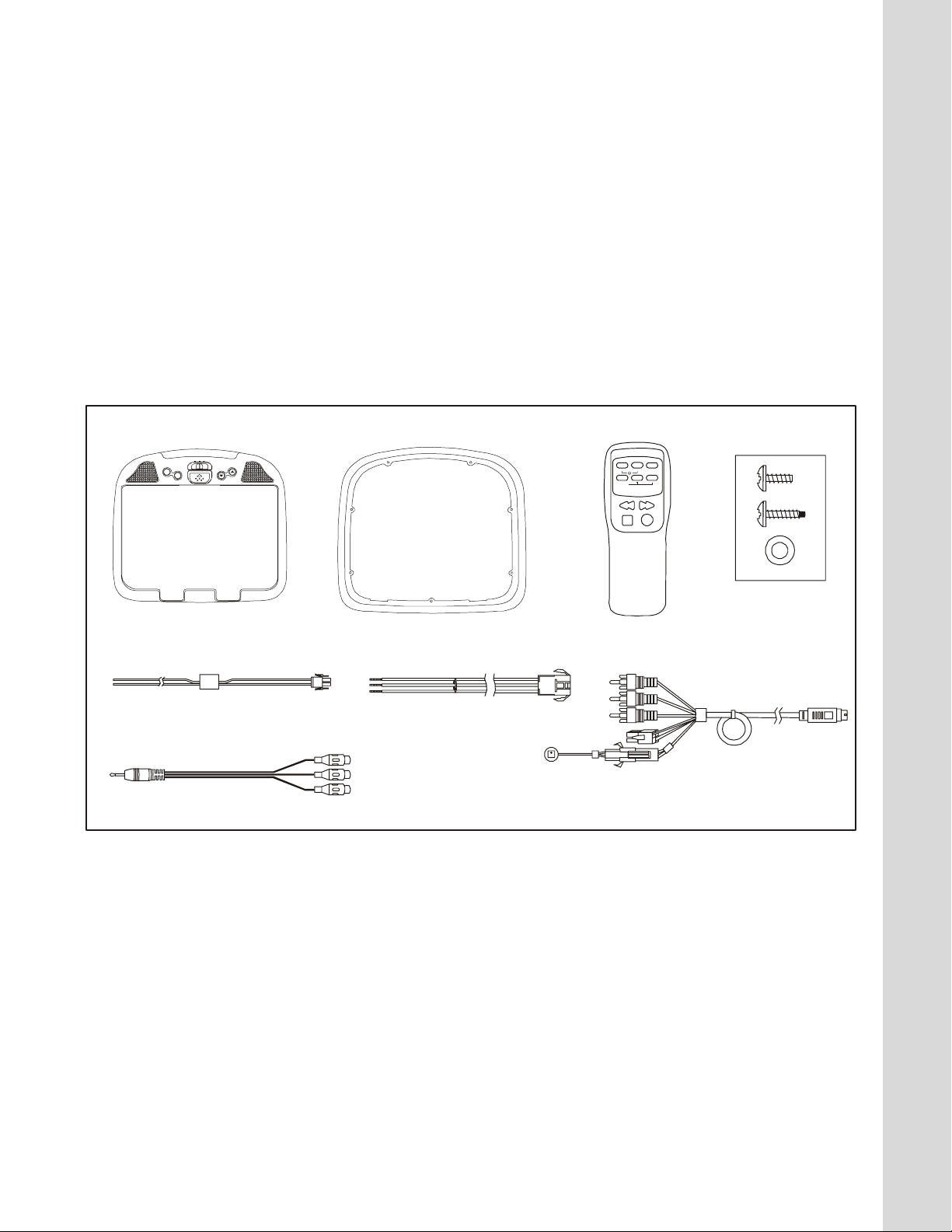
MATERIALS INCLUDED IN THIS PACKAGE:
V
1) MM801 Video Monitor (P/N 136D3649) – 1pc
2) Trim Ring (P/N 102C4007) – 1pc
3) Remote Control (P/N : 136B3650) – 1pc
4) Hardware Package:-
♦ #4 x 5/16” Screws – 7 pcs
♦ #8 x 5/8” Self Drilling Screws – 4 pcs
♦ #8 W ashers – 4 pcs
5) 2 Pin Power Wire Harness with choke (P/N 1 12B3143) – 1 pc
6) Dome light Harness (P/N 1 12B31 10) – 1 pc
7) Accessory Harness (P/N 8010730) – 1pc
8) A/V Adapter Cable (P/N 112B3227) – 1pc
Installation Guide
1. 2.
ON OFF AUTO
POWER
MENU/
ENTER
5.
8.
TOOLS REQUIRED:
3.
LCD
CP
MENU/
ENTER
REW FWD
PLAY
6. 7.
4.
SOURCE
+
STOP
#2 Phillips Screwdriver
#1 Phillips Screwdriver
Utility or Razor Knife or Shears
Wire Strippers
Upholstery hook tool (for removal of panels as necessary)
Electrical Tape
Masking Tape
Multimeter (to verify 12 volt DC and continuity: Do not use a test light or logic probe)
Marker pen – to mark headliner
Scribe (to mark trim ring if used)
Misc. electrical connectors (to connect to vehicle power source). Requirements will vary from vehicle to
vehicle.
3
Page 4

GENERAL INSTALLATION APPROACH:
1) Decide upon system configuration and options that will be installed (i.e.: what components, VCP,
Tuner, RF Modulator/external amp, remote headphones, DVD, etc.).
2) Review all manuals to become familiar with electrical requirements and hook ups.
3) Decide upon mounting locations of all components and method of mounting.
4) Prep the vehicle by removing any interior trim necessary to gain access to vehicle's wiring as well as
all areas where interconnecting wire harnesses will need to be located. If any access holes need to
be cut into the vehicle (headliner, other trim components etc.), this should be done now as well.
5) Route the wiring harnesses throughout the vehicle as necessary. (Refer to the Wiring Diagrams in
this manual as well as the wiring instructions for the individual components and accessory options
being installed). Be sure that all wiring is protected from sharp edges and is routed in such a manner
that it will not be pinched when all components and interior trim are fully installed. Be sure to leave
enough slack in the wiring at each component to allow working room.
6) Remove all A/V system components from their packaging and place them loosely in the vehicle at
their respective locations.
7) Connect all components together (electrically) and verify proper operation of all system functions.
Note: This is best done BEFORE components have been permanently mounted.
8) After verifying proper operation of the system, proceed to mount each of the components.
9) When all components are mounted, recheck function of entire system again to ensure that no wiring
was pinched or connected improperly during final installation.
Installation Guide
4
Page 5

VEHICLE PREPARATION:
1) Locate an accessory power source (+12v when key is in the ACC. and run positions, and 0v when key
is off). Also locate a good ground wire. Generally, these wires can be found at the ignition switch or
fuse-box.
2) The mounting method and location will vary from vehicle to vehicle, so this manual will only focus on
the installation of the video monitor and related console accessories.
3) Generally , the best location for the video monitor is where the vehicle's factory dome light is installed.
The monitor should be located in such a manner that it can be comfortably viewed by rear seat
passengers. NEVER INSTALL THE MONITOR IN A PLACE WITHIN THE DRIVER'S VIEW. THIS
IS NOT ONLY DANGEROUS, BUT IT IS ALSO ILLEGAL.
4) Once the mounting location of the monitor has been determined, there may be additional preparation
work necessary, depending on the vehicle structure and installation method. Some of the steps that
may be required are:
A) Removal of the vehicle's dome light.
B) The headliner may need to be trimmed.
Installation Guide
5
Page 6

TRIM RING INSTALLATION:
This page only covers special installation considerations for the trim ring installation.
If the video monitor is to be installed in a vehicle with the trim ring, it may need to be trimmed to fit the
contour of the vehicle headliner.
1) In this installation, the video monitor is mounted directly to the overhead cross-member in the roof
using the mounting screw bosses. These screw bosses should contact the cross-member directly (i.e.: no gap between the screw boss and the roof structure). Also, be sure that the screws
do not pierce the outer roof skin when fully fastened to the cross-member. The trim ring is
attached to the video monitor using the perimeter screw bosses. It is important that the screws
used in this installation are not overtightened, and that the video monitor and trim ring are mounted
in such a way that the assembly does not distort (or bend) when the mounting screws are tightened. An alternate method is to use a piece of plywood (5"x9"x3/4"). First secure the plywood
block to the cross-member, then screw the monitor into the plywood. See the drawing on p age 7.
2) It is best to mount the video monitor to the roof structure without the trim ring first. There should
be a gap between the headliner and the outer flange of the video monitor. The trim ring should be
cut to full this gap. Apply masking tape to the outer surface of the trim ring in the areas where the
cut will be made.
3) Mark the cut to follow the necessary contour of the roof. The suggested method of marking is as
follows:
A) First mark the narrowest point of the trim ring on the masking tape. Be careful to
consider not only left-right location, but fore-aft location.
B) Using the handle of a screwdriver, make a “transfer marking tool”. See diagram
below. Place the tool against the roof and the marker against the masking tape on
the mini-console. Trace the cut to be made around the entire perimeter of the trim
ring.
C) Cut the trim ring using a Dremel Tool.
D) Check the fit of the trim ring and make any minor adjustments necessary.
4) The trim ring can be painted or covered with a material that matches the headliner before assembling the trim ring to the video monitor.
5) The finished trim ring should be attached to the video monitor, then attach the assembly to the
roof.
Cut line
Lowest point mark
Tape marker to screwdriver. Starting at your mark
for the lowest point, trace the contour of the roof
Installation Guide
Headliner
6
Page 7

MOUNTING THE TRIM RING
Installation Guide
Roof
Roof Support
Headliner
5"x9"x3/4" Plywood
Block
(4) #8x1" self drilling
screws
Trim Ring
Video Unit
(4) #8 flat washers
(4) #8x3/4" self tapping
screws
7
Page 8

MM801
A
A
Dome
Light
1
Video Outp ut
Red: +12VDC
Accessory Ckt.
(Install 5A
Inline Fuse)
Black: Ground
IR LED:
Clean the IR Receiver Window on the front of the VCP.
Remove Adhesive Backing and Apply IR LED to IR
Window on the Face of the VCP.
Power Harness
item #5
Power
Connector 4 Pin
FUSE
DC IN
“Y” Adapter
for use with
Non-Stereo
Installations
RF OUT
Accessory
Harness
item #7
Red RCA (Audio Right)
NT.IN
White RCA (Audio Left)
OUT
Ye llo w RCA (Vide o)
udio Output
forFM Mod.
1) Insert the Circular Mini-Din Connector of the source Component Harness through the wire tie loop
on the main PCB and into the Mini-Din Connector on the main PCB.
2) Pull the wire tie loop tight and cut off the excess.
3) Connect the Power Harness to the mating connector on the Video Monitor .
4) Connect the power harness to the vehicle’s electrical system through an In-Line 5-Ampere fuse by
tapping into an accessory hot line.
5) Verify all functions of the System before final mounting of the finished assembly.
Installation Guide
8
Page 9

CONNECTING THE DOME LIGHTS
The dome lights in the video monitor require three connections to the vehicle's wiring. There are two
common types of dome light circuits used, positive or negative switched. Positive systems supply voltage to the interior lights to turn them on, negative switched systems apply ground to illuminate the bulbs.
To determine which system you have you must locate the wires at the dome light. On a positive switched
system, with all the doors closed and the lights out, both wires at the dome light will rest at ground. When
the light is activated, one of these wires will switch to +12 vdc. This is the vehicle's switching wire. On a
negative switched system, with all the doors closed and the lights out, both wires at the dome light will
rest at + 12vdc. When the light is activated, one of these wires will switch to ground. This is the switching
wire.
For positive systems, connect the violet / brown (Lamp auto) wire to the vehicle's switched wire. Then
connect the red / black (lamp on) wire to a fused constant 12 volt source and the black / red (lamp
common) wire to a good ground. Positive systems are commonly found on Ford vehicles.
For negative systems, connect the violet / brown (Lamp auto) wire to the vehicle's switched wire. Then
connect the red / black (lamp on) wire to a good ground and the black / red (lamp common) wire to fused
constant 12 volt source. Negative systems are commonly found on General Motors and import vehicles.
Note:
Some vehicles which incorporate transistorized control of the dome light circuit, such as the 1999
Dodge Caravan, may require that the violet / brown (Lamp auto) wire be connected to the door pin
switch wire, as the additional current draw of the Monitor's lights may not be supported by the output
of the vehicles body control computer.
Installation Guide
Positive Switched Dome lighting
To 3 pin
connector
on Monitor
Factory Dome light circuit
To
constant
+12vdc
9
Red / black - Lamp on
Black / red - Lamp common
Violet / brown - Lamp Auto
Factory Door ajar
switch or Body
Control computer
To
constant
+12vdc
Page 10

Negative Switched Dome lighting
To 3 pin
connector
Factory Dome light circuit
Red / black - Lamp on
Black / red - Lamp common
Violet / brown - Lamp Auto
Factory Door ajar
switch or Body
To
constant
To
constant
Troubleshooting:
SYMPTOM:
No power at Video Monitor
Power but no video or
sound
Picture, but no sound
REMEDY:
-Verify +12 VDC on Red wire at 2 pin Power Harness behind video
monitor. Verify ground connection with continuity test from known
good ground to black wire at 2 pin Power Harness
-Verify that the correct source is selected (i.e.: 1 or 2). Verify that the
source is on and playing a known good media (such as a videotape).
Verify connections at both ends of the source component harness.
-Verify that the headphones are turned on; check head phone batteries
-Verify that power is available to the FM Modulator; make sure modulator is tuned to the correct FM station
Installation Guide
10
Page 11

Installation Guide
This Page Intentionally Left Blank
11
Page 12

© Copyright 2004 AEC 150 Marcus Blvd. Hauppauge, NY 11788
128-7036
 Loading...