

Page 1
MM530
5.3" LCD HEADREST MONITOR
1
1
Page 2
EXPLANATION OF GRAPHIC SYMBOLS
CAUTION
RISK OF ELECTRIC SHOCK
DO NOT OPEN
CAUTION: TO REDUCE THE RISK OF ELECTRIC SHOCK DO
NOT REMOVE COVER (OR BACK) NO SERVICEABLE PARTS
INSIDE REFER SERVICING TO QUALIFIED SERVICE
PERSONNEL
The lightning flash with arrowhead symbol, within an equilateral triangle, is intended to alert the user to the presence of
uninsulated “dangerous voltage” within the product’s enclosure that may be of sufficient magnitude to constitute a risk of
electric shock.
The exclamation point within a triangle is intended to alert the
user that important operating and servicing instructions
W ARNING:
TO PREVENT FIRE OR ELECTRIC SHOCK HAZARD, DO NOT OPEN
CAUTION:
1. This product is designed to operate with a 12 volt, negative ground
battery system.
2. Refer to the electrical connection diagram to avoid wrong connection
of the electrical system.
Always use authorized service center for service assistance.
3. Do not operate the monitor at temperatures below 32°F (0°C) or
above 104°F (40°C).
4. Keep the monitor clean and dry.
5. Never attempt your own repairs. This unit should be installed and
repaired by qualified technicians or service personnel..
6. Do not drop the monitor or expose to strong impacts.
7. Do not expose to direct sunlight for extended periods of time.
8. Use proper insulation material to prevent short-circuiting of the supply
system.
2
Page 3

IMPORTANT
An LCD panel and/or video monitor may be installed in a motor
vehicle and visible to the driver if the LCD panel or video monitor is
used for vehicle information, system control, rear or side observation
or navigation. If the LCD panel or video monitor is used for television
reception, video or DVD play, the LCD panel or video monitor must be
installed so that these features will only function then the vehicle is in
‘park’ or when the vehicle’s parking brake is applied.
An LCD panel or video monitor used for television reception, video or
DVD play that operates when the vehicle is in gear or when the parking
brake is not applied, must be installed to the rear of the driver’s seat
where it will not be visible, directly or indirectly, to the operator of the
motor vehicle.
A. Precaution:
1. Before installation, verify that it will not damage electrical wires, fuel
lines, brake lines, hoses, exhaust system components or any other
items that will impair the operation of the vehicle.
2. Ensure the cable has already been pulled through the supporting
pipe before installing the base into the headrest. Ensure there is no
foreign material trapped inside the enclosure before installing the
monitor into the base.
3. Tighten all screws/bolts/nuts securely for installation.
4. To avoid electrical hazards, do not disassemble the monitor.
5. Use only the supplied cables. Disconnect all cables from the
signal source before disconnecting it from the monitor.
6. When cleaning, make sure the system is unplugged from the power
source. Do not use liquid cleaners or aerosol cleaners. Use a damp
cloth to clean the unit.
3
Page 4
B. Contents:
1. 1 x Main Unit MM530
2. 1 x A V Adapter Cable
3. 1 x Din-to-RCA Cable
4. 1 x Din Cable Clip
5. 1 x Owner’s Manual
6. 1 x Fan Bracket
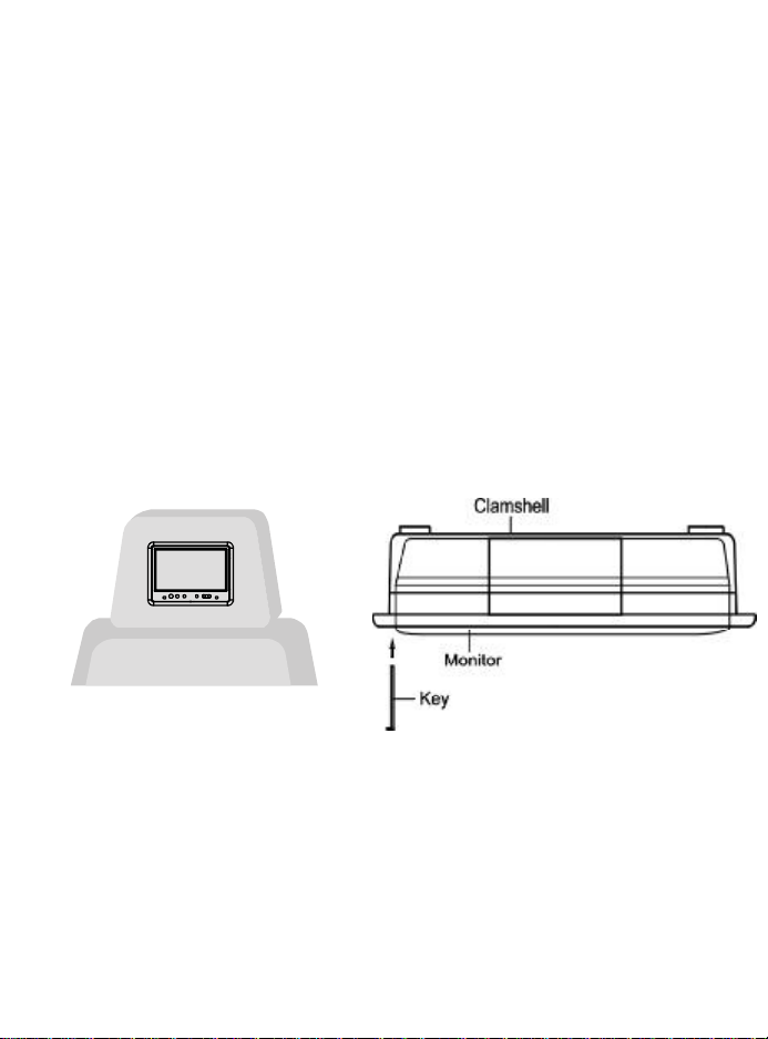
C. Installation:
Front View Top View
1. Installation will vary from vehicle to vehicle, as headrests in vehicles
are not standard.
2.This unit is intended for installation by professional installers.
3.The kit consists of the screen assembly, a clam shell housing and 1
key to remove the screen from the housing.
4
Page 5

Headrest Mounting:
1) Remove the headrest f
from the vehicle for easiest installation.
2) Lay headrest on a flat surface.
3) Using a Permanent Marker,
mark headrest material
along the exterior of the
Mounting tray .
Monitor
Mounting
Tray
4) Remove the Trim Ring and
mark an “X” from corner to
corner as shown.
5
Page 6

5) Using the utility knife, cut the
headrest material along the “X”
lines. Do not cut the material
along the other lines at this
time.
6) This will leave you with an “X” cut
as shown.
7) Pull the flaps up and cut the foam
beneath the material to the
proper depth. Cut all four sides
of the foam.
8) Using your fingers, tear the foam
out of the headrest leaving a
recess where the shell will be
inserted.
NOTE: At this point you will need to
install the harness up through the
area into the recess. It may be helpful to follow one of the posts and tie
wrap it to the post for restraint.
6
Page 7

9) Lay the flaps of the headrest material down into the recess and insert the Mounting Tray into the recess. Check for fit. If it does not fit
properly, you may need to remove
some more foam.
NOTE: The Mounting Tray will need to
be secured to the headrest, either
by using tie straps, screws, etc...
10) Guide the cable through the side
opening of the Mounting Tray and
plug it into the Monitor. Make sure
the connector locks into place.
Insert the Monitor into the Mounting Tray and secure the cable
using tie wraps or screws
11) Turn the Monitor around and in-
sert it into the Mounting Tray housing. Snap into place.
12) Connect the Monitor‘s DIN Cable
to the external video source output signal (from VCP/DVD, TV
Etc.)Test the system to verify
proper installation.
7
Page 8

Fan Bracket Mounting*
The monitor can be mounted on a variety of surfaces using the
supplied fan bracket.
Select a location for the monitor and find a suitable surface to mount
the fan bracket. The mounting location* should be as firm, flat and
smooth as possible to ensure maximum adhesion. If the area is not
flat the bracket can be bent to conform to the shape of the surface.
Clean the area thoroughly and make sure that is dry before attempting
to mount the bracket. Remove the backing from the adhesive pad on
the bottom of the bracket and carefully place it in the desired mounting
location and press down firmly. Carefully align the mounting hole on
the bottom of the monitor with the screw on the top of the bracket.
Release the locking lever and turn the locking knob until it is tight.
Adjust the monitor angle and tighten the locking lever.
Screw
Screw
Locking Knob
Spanner
Locking Lever
*Note: Please read the important notice on page three about monitor
location.
8
Page 9

D. Controls/Indicators/Connectors:
Front View
5678 9
1. A V Input Jack
2. Power Button
3. Source Button
4. Wide Button
5. Fan Bracket Mounting Hole
6. Picture Select Button
7. Volume Down Button
8. Volume Up Button
9. Headphone Jack
9
Page 10

Rear View
9.DIN Jack
10.Video (Yellow)
11.Audio Left (White)
12.Audio Right (Red)
13.Red +12 VDC
14.Black Ground
10
Page 11

E. Operation:
1. Connect the external AV source output signal (from VCP, DVD, TV
etc.) to the A V jacks (Video-yellow , Right Audio-red, Left Audio-white).
2. Press power button (2) to turn the monitor on and off. The backlighting for the buttons will illuminate.
3. Press the volume up (7) or down (6) button to adjust the volume level.
4. Press the picture button (5) to adjust the picture quality. The adjustments will be shown on the On Screen Display in the following se
quence: Color, Brightness, Contrast, and TINT. While in the picture
select mode (video adjustment), press the volume up button (7)
to increase the selected adjustment level or press the volume
down button (6) to decrease the level.
F. Specification:
1. LCD Panel: Color Liquid Crystal Display (LCD)
Monitor
2. Resolution: 480 x 234
3. V ideo Format: NTSC
4. Power Source: +12 VDC
5. Power Consumption: 600ma
6. Dimensions (W x H x D): (5.47” x 4.13” x 0.87”)
139 x 105 x 22 mm
7. Weight: 10.4oz (295g)
11
Page 12

12 MONTH LIMITED WARRANTY
Applies to Movies To Go Mobile Video Products
AUDIOVOX ELECTRONICS CORP. (the Company) warrants to the original retail
purchaser of this product that should this product or any part thereof, under
normal use and conditions, be proven defective in material or workmanship
within 12 months from the date of original purchase, such defect(s) will be repaired or replaced
with reconditioned product (at the Company's option) without charge for parts and repair labor. A
game controller, if supplied, is similarly waranteed for ninety (90) days.
To obtain repair or replacement within the terms of this Warranty, the product is to be delivered
with proof of warranty coverage (e.g. dated bill of sale), specification of defect(s), transportation
prepaid, to the Company at the address shown below.
This Warranty does not extend to the elimination of externally generated static or noise, to correction
of antenna problems, to costs incurred for installation, removal or reinstallation of the product, or
to damage to digital memory cards, discs, speakers, accessories, or vehicle electrical systems.
This Warranty does not apply to any product or part thereof which, in the opinion of the Company,
has suffered or been damaged through alteration, improper installation, mishandling, misuse,
neglect, accident, or by removal or defacement of the factory serial number/bar code label(s).
THE EXTENT OF THE COMPANY'S LIABILITY UNDER THIS WARRANTY IS LIMITED TO THE
REPAIR OR REPLACEMENT PROVIDED ABOVE AND, IN NO EVENT, SHALL THE COMPANY'S
LIABILITY EXCEED THE PURCHASE PRICE PAID BY PURCHASER FOR THE PRODUCT.
This Warranty is in lieu of all other express warranties or liabilities. ANY IMPLIED WARRANTIES,
INCLUDING ANY IMPLIED WARRANTY OF MERCHANTABILITY, SHALL BE LIMITED TO THE
DURATION OF THIS WRITTEN WARRANTY. ANY ACTION FOR BREACH OF ANY
WARRANTY HEREUNDER INCLUDING ANY IMPLIED WARRANTY OF MERCHANTABILITY
MUST BE BROUGHT WITHIN A PERIOD OF 24 MONTHS FROM DATE OF ORIGINAL
PURCHASE. IN NO CASE SHALL THE COMPANY BE LIABLE FOR ANY CONSEQUENTIAL
OR INCIDENTAL DAMAGES FOR BREACH OF THIS OR ANY OTHER WARRANTY, EXPRESS
OR IMPLIED, WHATSOEVER. No person or representative is authorized to assume for the
Company any liability other than expressed herein in connection with the sale of this product.
Some states do not allow limitations on how long an implied warranty lasts or the exclusion or limitation
of incidental or consequential damage so the above limitations or exclusions may not apply to
you. This Warranty gives you specific legal rights and you may also have other rights which vary
from state to state.
U.S.A. : AUDIOVOX ELECTRONICS CORPORATION 150 MARCUS BLVD., HAUPPAUGE,
NEW YORK 11788 l 1-800-645-4994
CANADA : CALL 1-800-645-4994 FOR LOCATION OF WARRANTY STATION SERVING
YOUR AREA
128-6924E
© 2005 Audiovox Electronics Corporation 128-7456A
12
 Loading...