

Page 1

i':-:"~;:
'::-.;;J
.~
'J
K
"
t
.l
~
!
: {
}
,
.;::;"::1
FORM
:."
":
~
# 2756
Rev. B
10/98
Page 2
[ THIS MANUAL, YOUR KIT AND YOu-~
This Cruise Control Kit is a microprocessor based Cruise Control. It is designed for ease of
installation and can be used with most cars, light trucks and vans. Carefully follow the installation
procedures in this manual for best results.
DO NOT INSTALL THIS SYSTEM ON A DIESEL POWERED VEmCLE WmCH
HAS A MANUAL TRANSMISSION WITHOUT A DISENGAGEMENT
SWITCH (250-4206) ON THE CLUTCH PEDAL ASSEMBLY
Your vehicle must have a VSS (Vehicle Speed Sensor) wire or an available signal generator for
installation of this Cruise Control. Please consult vendor's Application Guide.
Low displacement engines with limited vacuum will get better performance if a vacuum reservoir
is installed. Vacuum reservoirs, pumps, regulators and other accessories are available from your
dealer, automotive service center or most automotive parts outlets.
All through the instructions there are W ARNINGS, CAUTIONS, AND NOTES that are meant
to make it easier for you to put the Cruise Control on your vehicle and safer to use. We have
gathered these tips from people across the country who have told us about their problems and
how they worked them out. Even with all these reports from the field, we cannot cover every
condition which you might encounter, there are just too many different vehicle makes and models.
We do our best to tell you how to handle most vehicles, but we must Denend On Your Good
Judgment for dealing with the rest.
Therefore, we believe you can understand why we strongly urge you to think carefully about
what could happen to you, your passengers and your vehicle if you use any tools, parts, fastening
methods, routing or procedures which are not described in this manual.
There is NO drain on the battery if the control switch is left on. The Cruise Control needs no
regular service.
ALL RIGHTS RESERVED
PRINTED IN THE USA
,- 127S6, Page 2
Page 3
~ T ABLE OF CONTENTS ~
I.
4- .5
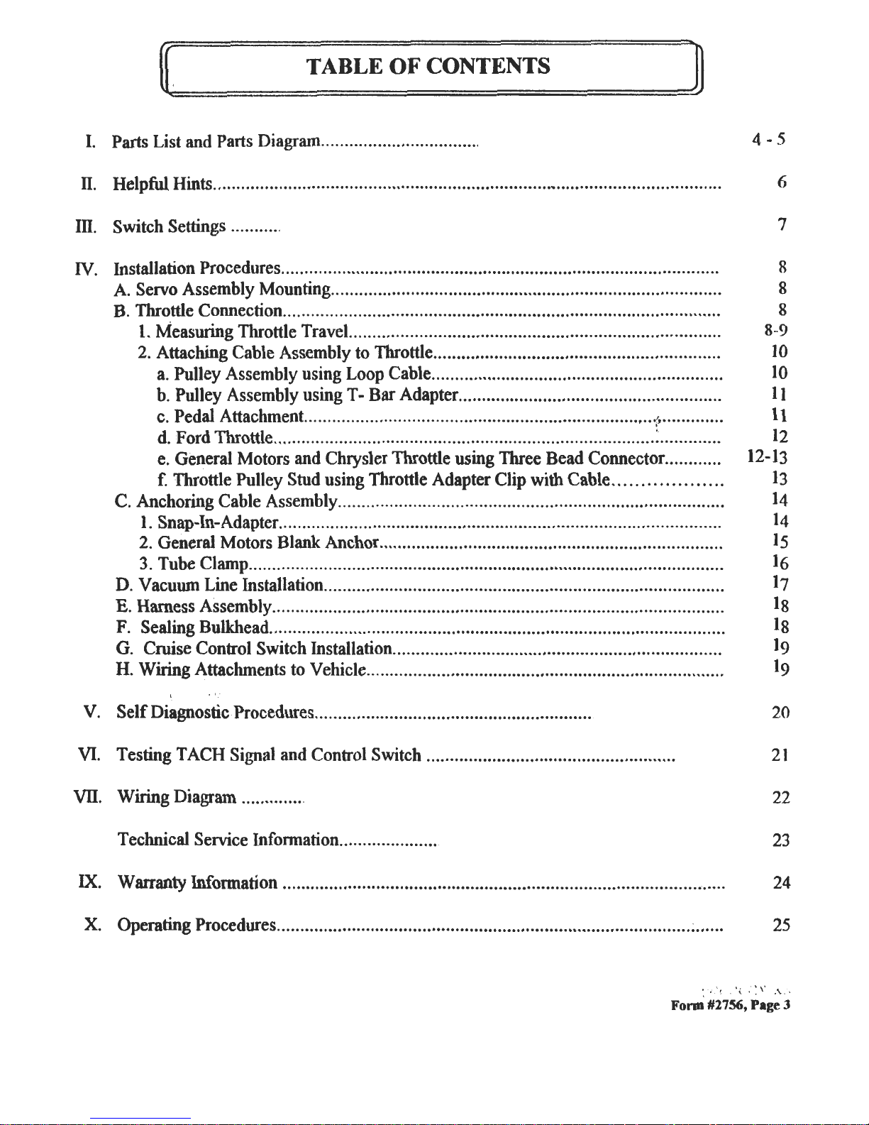
Parts List and Parts Diagram
n.
Helpful Hints
6
Ill.
Switch Settings
7
IV.
8..
1
1
1
1
1
12-1
1
1
1
1
1
1
1
1
]
1
Installation Procedures A. Servo Assembly Mounting B. Throttle Connection I. Measuring Throttle Travel 2. Attaching Cable Assembly to Throttle a. Pulley Assembly using Loop Cable b. Pulley Assembly using T- Bar Adapter c. Pedal Attachment ,
d. Ford Throttle e. General Motors and Chrysler Throttle using Three Bead Connector f. Throttle Pulley Stud using Throttle Adapter Clip with Cable C. Anchoring Cable Assembly I. Snap-In-Adapter 2. General Motors Blank Anchor 3. Tube Clamp D. Vacuum Line Insta1lation E. Harness Assembly F. Sealing Bulkhead G. Cruise Control Switch Installation H. Wiring Attachments to Vehicle
v.
Self Diagnostic Procedures
20
VI.
Testing TACH Signal and Control Switch
21
VII.
Wiring Diagram
22
Technical Service Infonnation
23
IX.
24
Warranty Infonnation
x.
Operating Procedures
25
:' '( 'z : : \: ,\ ,
Form #2756, Page 3
8
8
8
9
O
O
1
1
2
3
3
4
4
5
6
7
8
8
9
9
Page 4
PARTS LIST
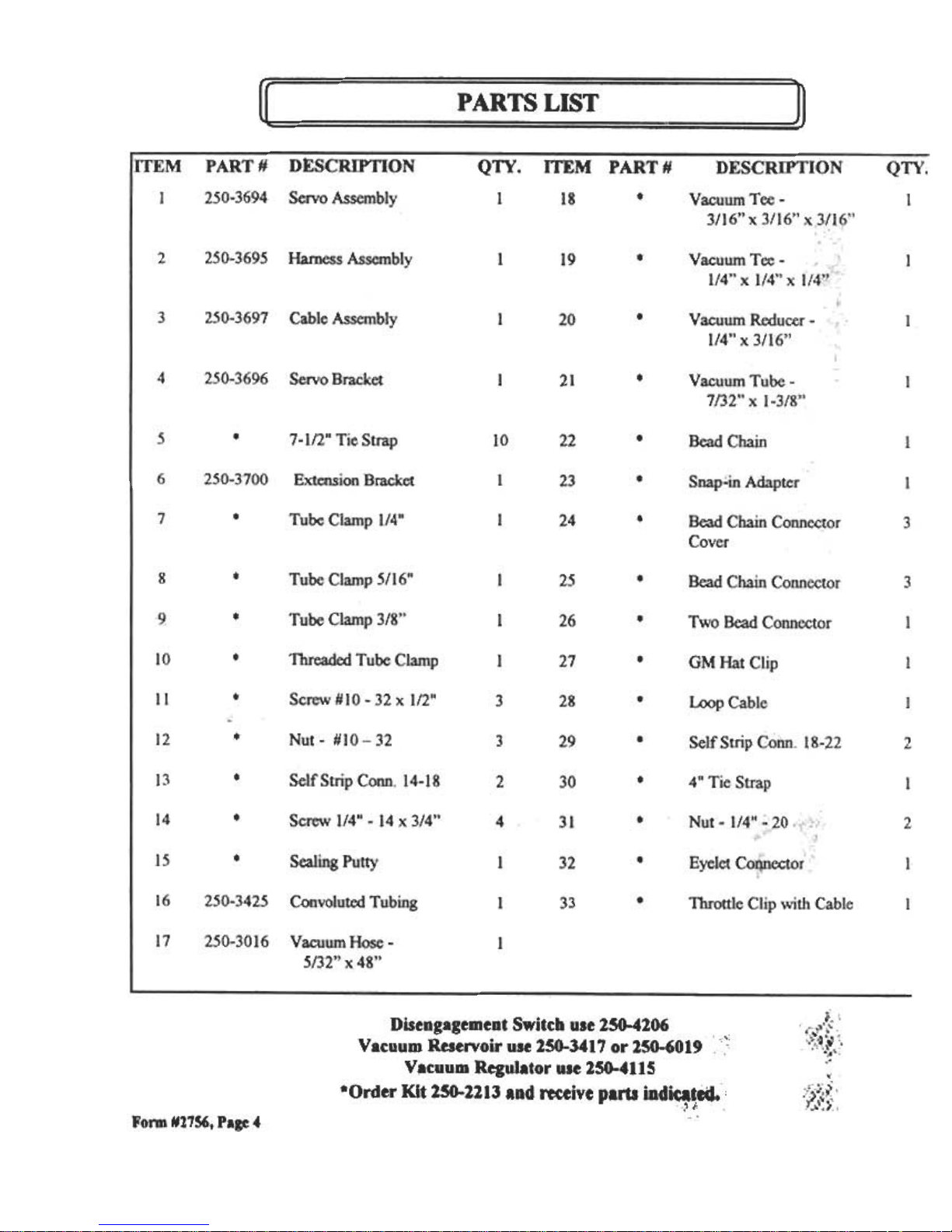
Disengagement Switch use 250-4206 , "
Vacuum Reservoir use 250-3417 or 250-6019 ,','
Vacuum Regulator use 250-4115
*Order Kit 250-2213 and receive parts indi~~~.;
"
Form #2756, Page 4
Page 5
r~
~
~)
~
O
o
u
O
o
o
o
0
()
O
D
","-..I
~
~
?
@
.-.
~
~
~
@
~
11
lti
~
@
@
"
. """'"",""c, ,'
~ ~
"."."".",.,:,".-J,!22
~~~-&~.~
Form #2756, Page 5
Page 6
'C" : '," II :!!ELPFUL IDNTS ~
1. Before Starting Installation:
Familiarize yourself with the Installation Instructions and Cruise Control's components.
A. If vehicle is equipped with an ANTI- rnEFf RADIO. the radio c<xie must be written down prior to
disconnecting battery cable. The c<xie must be re-entered wbtJI the negative battery cable is reinstalled.
B. If vehicle is equipped with an AIR BAG. it is advisable to disconnect negative battery cable. However.
remember that some vehicles retain power to the air bag sysm when battery is diSCOOlleCted.
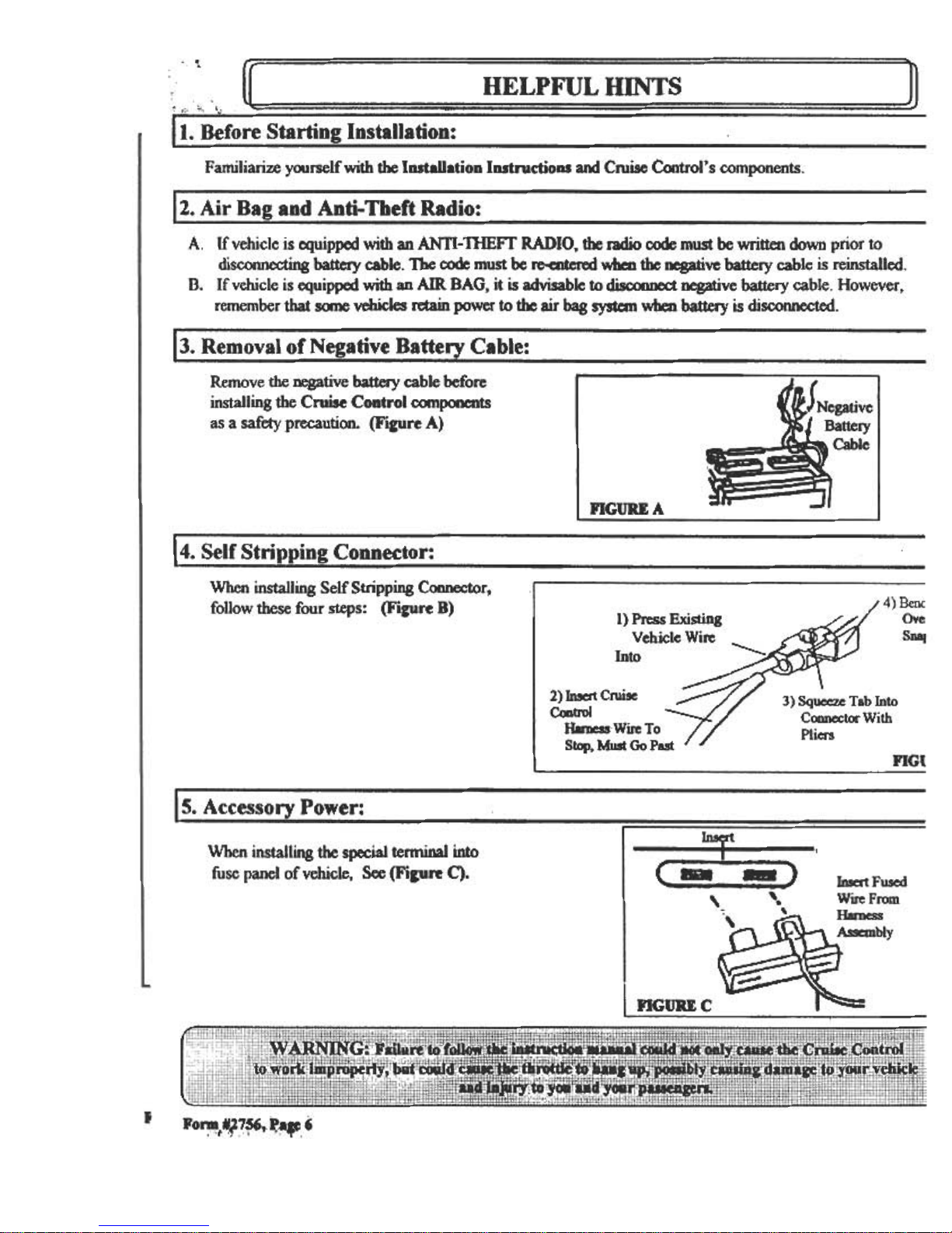
3. Removal of Negative Battery Cable:
Remove the negative battery cable before
installing the Cruise Control C(XDponents
as a safety precaution. (FilUre A)
Battery
FIGURE A
--
4. Self Stripping Connector:
When installing Self Stripping Connector, '
Ifollow these four steps: (FilUre B)
1) Press Existing
Vehicle Wire
Into
Ove
SD8J
3) Squeeze Tab Into
Connector With
Pliers
2) Insert Cruise
Coob'Ol
llamcsswire To
Stop. Must Go Past
FIG{
15. Accessory Power:
h1sert
When installing the special tern1inal into
fuse panel of vehicle, See (Fipre C).
Insert Fused
Wire From
Harness
Assembly
,
InGOUc ~
I
.
FO~tY7ft(J,~.~,6
, '.
-
Page 7
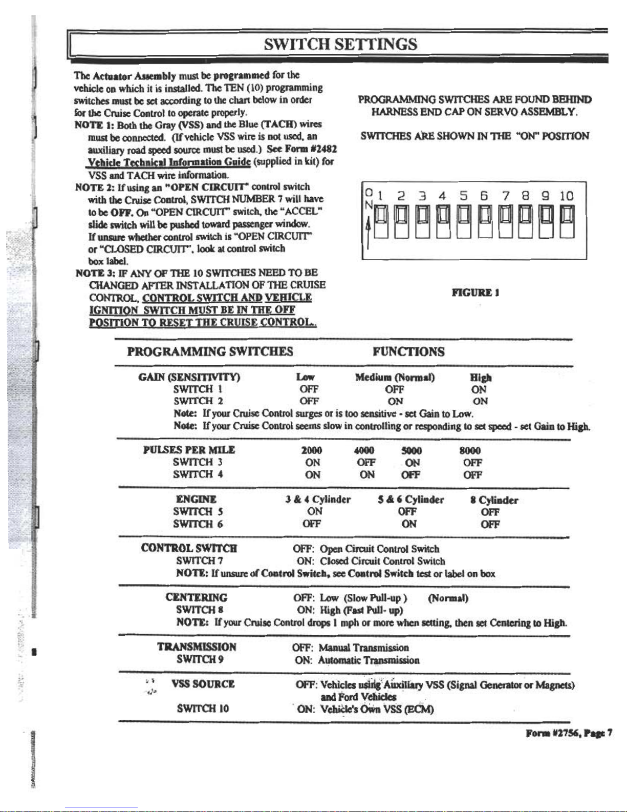
PROGRAMMING SWITCHES ARE FOUND BElDND
HARNESS END CAP ON SER YO ASSEMBL y .
SWITCHES ARE SHOWN IN nIB "ON" POSmON
The Actuator Assembly must be programmed for the
vehicle on which it is installed. The TEN (10) programming
switches must be set according to the chart below in order
for the Cruise Control to operate properly.
NOTE I: Both the Gray (VSS) and the Blue (TACH) wires
must be connected. (If vehicle VSS wire is not used. an
auxiliary road speed source must be used.) See Form 12482
Yehicle Technical Information Guide (supplied in kit) for
VSS and T ACH wire information.
NOTE 2: Ifosing an "OPEN CIRCUIT" control switch
with the Cruise Control, SwrrCH NUMBER 7 will have
to be OFF. On "OPEN CIRCUIT' switch, the ..ACCEL "
slide switch will be pushed toward passenger window.
If unsure whether control switch is "OPEN CIRCUIT'
or "CLOSED CIRCUIT', look at control switch
box label.
NOTE 3: IF ANY OF THE 10 swrrCHES NEED TO BE
CHANGED AFTER INST ALLA TION OF THE CRUISE
CONTROL, CONTROL SWITCH AND VEHICLE
IGNITION SWITCH MUST BE IN mE OFF
POSITION TO RESET THE CRUISE CONTROL..
FIGUREl
PROGRAMMING SWITCHES
FUNCTIONS
GAIN (SENSlTlVrrY) Low Medium (Nonnal) High
SWITCH 1 OFF OFF ON
SWITCH 2 OFF ON ON
Note: If your Cruise Control surges or is too sensitive -set Gain to Low.
Note: If your Cruise Control seems slow in controlling or responding to set speed -set Gain to High.
PULSES PER Mn.E
SWITCH 3
SWITCH 4
2000
ON
ON
4000
OFF
ON
5000
ON
OFF
8000
OFF
OFF
ENGINE
SWITCH S
SWITCH 6
3 & 4 Cylinder
ON
OFF
5 & , Cylinder
OFF
ON
B Cylinder
OFF
OFF
CONTROL SWITCH OFF: Open Circuit Control Switch
SWITCH 7 ON: Closed Circuit Control Switch
NOTE: If unsure of Control Swikht see Control Switch test or label on box
CENTERING OFF: Low (Slow Pull-up ) (Normal)
SWITCH 8 ON: High (Fast Pull- up)
NOTE: If your Cruise Control drops 1 mph or more when setting. then set Centering to High.
TRANSMISSION
SWITCH 9
,,':v
:")"
vss SOURCE
OFF: Manual Transmission
ON: A~tomatic T~mission
OFF:Vehicles ~dg:A1lxi.fary VSS(Signal Generator or Magnets)
., .
alldFord Vehicles
"ON: vehi~le's OWn vss'(ECM)
SWITCH 10
FonD N17S6, p. 7
Page 8
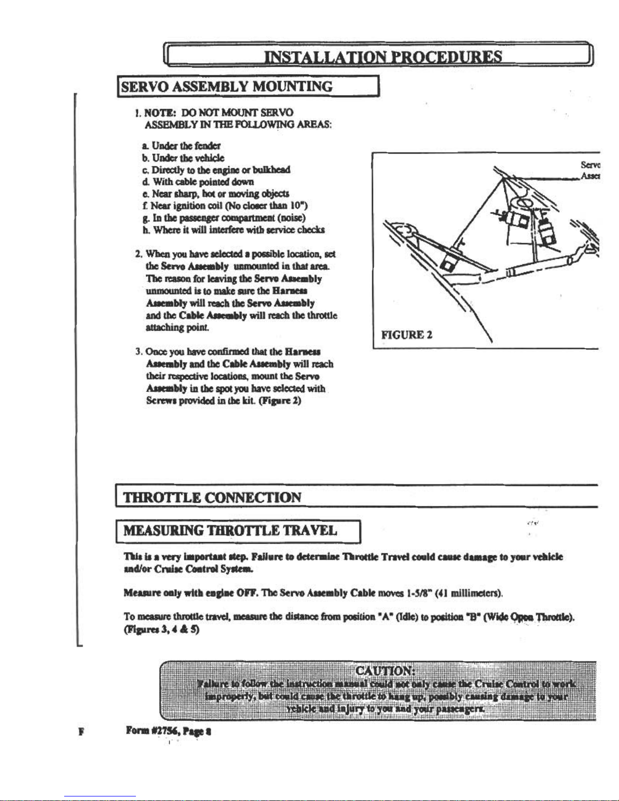
r SERVO ASSEMBL y MOUNTIN I
I. NOTE: 00 NOT MOUNT SERVO
ASSEMBLY IN nIB FOu.oWING AREAS:
a. Under the felKIcr
b. U..r the vehicle
c. DirectJyto the eDgiM or bi)llrhead
d With cable JX)inted ckJwn
e. Near sharp. bot or DMJViDg OOjects
f. Near ignition coil (No clC*r than 10-)
g. In the passenger --t (noise)
h. Where it will interfere with selVice checks
2. When you have selected a possible location. set
the Senro AIIeIDbly unmounttd in that area.
The rcason for leaving the Servo Auembly
unmounttd is to make ~ the Barneu
AIIeIDbly will ~h the Servo AIIeIDbly
and the Cable AIIeIDbly will reach the throttle
attachingpoint.
3. Once you have oonfirmcd that the Bar8ell
AueIDbly and the Cable AueIDbly win reach
their respective locations. mount the Sen'O
AIIeaIbly in tbe spot you have selected with
Screws provided in tbe kit. (Figure 2)
,',,'
MEASURING THROn'LE TRA VEL "
ni. i. a very importut ltep. Failure to detenniae nrottle Tnvel could caule damaF to yCMIr vehicle
lad/or Cnile Coatrol Syltem.
Me re only with eagiae OFF. The Servo Assembly Cable moves 1-5/8" (41 millimcters).
To ~ thrott1c tm'e1. oaswe the distance from position. A. (Idle) to position ~. (W~ ~~).
(Fiau~ 3, 4 & ~
F
Fona t17S6. p..
I c ,
Page 9

MEASUIUNG THROTfLE TRA VEL
"
, Continued
I. Make a mark on the throtde cable when the
throttle is in the idle position. (Figure 3)
2. Depress aa:elerator ~ aIMi make a mark
on the throttle cable when the throttle is in
the wide open position. (Ficure 4)
FIGURE 4
3. Measure the di~~ between the two marks.
(Fipre ~ If di~~ is greater than 1-5/8"
(41milli~~), SO to the next page. If it is less,
SO to Step D.
4. If the tbfotde travel is less than 1-5/8" (41
milli~). yw must use Bead Chaia to
provide Ilack. NOTE: SI8Ck Is the distaace
tM CIhIe A-.bly 8O\'a before the throttle
ItartI ..~Bach bead of the chain added
wiI1live YCMi 1~~ (3 millimeters) of slack.
(E~ rr~~etravels 1-1/2"
(38 ~jlli~~).yw will ~ one (1) IJe.L
NOTE: To beads yw must use the Bead
Cbai8~ ~ Cbal8 CODaector and the Bead
Cbai8 ~r. Do not Q)UDt the bead used with
the Bead BIJa CODDector.
I
AAet do!InId8iIII ~ throttle travel, continue
to the aextlCCtion.
Form 117S6, Pa&e9
Page 10

A TT ACHING CABLE ASSEMBL y TO THROTTLE
This section will cover the proper ways to use the hardware available. Each section contains sample illustrations showing how
the coMector is used in an actual installation. It must be noted however, that you should have an understanding of howeach
attachment method works so that a proper installation is achieved.
There are six (6) different types of throttle connections.
~
A. Pulley Assembly using Loop Cable
B. Pulley Assembly using T -Bar Adapter
C. Pedal Attachment
D. Ford Throttle
L General Moton and Chrysler Throttle
uling Two Bead ConDector
F. nrottle Stud Attachment using Adapter Clip with Cable
Loop Cable
T -Bar Adapter
FIGURE 7
NOTE:
Whe. uliDg the Scad Chain Connector to connect
the Bead ChalD to the Cable Assembly you must
alwayl use the Bead ChaiD Cover. (Figure 7)
Failure to use the Scad Chain Cover could possibly
cause the Scad ChalD or the Cable Assembly to hang
i. the Bead ChaiD Connector causing the throttle to
be held iD a partially OpeD position. This coDditioD
cCMIld occur wheD the Cruise Control is nOt being used.
A. Pu1lev Assemhlv Usinp the LOOP CABLE
I. On some vehicles it may be necessary to remove
the air cleaner so the throttle pulley segment is
showing.
2. Set the pulley segment in an OPEN throttle
JX)$ition. and remove the throttle cable from the
pulley.
3. Hold the Loop Cable between the holes in each
side of the pulley. Slide the barrel at the end of
the throttle cable through the slotted hole, then
through the Loop Cable and into the second
hole. (Figure 8)
..Connect the Loop Cable to the Cable Assembly
using the Bead Chai. Connector .
NOTE: Use the Bead Chain Cover.
S. To 5«"Ure the Loop Cable to the throttle cable,
punch a small hole in the Bead Chain Cover
and slide the ." Tie Strap through the hole and
-' -.we to the existing throttle cable. (Figure 9)
r... '27!6, ..~ 10
Page 11

\
T -Bar Adapler
BeadCbain
Cdver
" Top Pulley
/ Segnle~t
Bead Chain
Conncctoi
nGURE 10
B. Pullev Assemblv mua/J UsinL-' the T-BAR
ADAPTER (250-4184J
I. Remove air cleaner to expose the dual pulley
segments.
2. Find the blank anchor that is located above the
throttle anchor. Follow the instructions in STEP B
for Anchoring Cruise Cable -page IS.
3. Attach a Bead CbaiD COnDectOr onto the Cable
Assembly. (Figure 10)
4. Attach the T-Bar Adapter to the top pulley
segment. Slide the Bead CbaiD Cover onto the
T-Bar Adapter-
S. Attach the T-Bar Adapter to the Bead CbaiD
ConDector. Make sure to slide the Bead CbaiD
Cover over Bead Chain Connector. (Figure II)
Cable Assembly
~
c Pedal Attachment
I. Select a Tube Clamp that fits arowtd the top of the
accelerator pedal shaft. Make sure the tabs of the
Tube Clamp point away from the bulkhead.
2. Attach the Bead Chain to the Cable Assembly
with a Bead Chain Connector. Make sure to use
a Bead Chain Cover.
3. After you detennine the length of Bead Chain
needed to attach to the accelerator pedal shaft,
cut Bead Chain aOO attach to the Eyelet Connector.
Make sure to use a Bead ChaiD Cover.
4. Put Screw ##10-32 x 1/2. through the holes in the
Tube Clamp. Slide the Eyelet Connedor over the
Screw. Thread Nut ##10-32 onto the Screw aOO
tighten. (Figure 12)
Threaded Tube Clamp
Bead
C~n
Cover
Screw #10 -32 x 1/2"
Eyelet Connector
Pedal Shaft
Nut 110- 32
nGURE 12
Fo...N!756, Paae'lt'
Page 12

--
INST ALLA TION PROCEDURES
FIGURE 13
-118
A TT ACHING CABLE ASSEMBL y
TO THROTTLE
D. Ford Throttle
I. Select a Tube Clamp that fits the throttle cable.
Make sure the tabs of the Tube Clamp point
away from the carburetor or air throttle, this
will prevent the throttle from banging.
(Figure 13)
2. Attach Cable Assembly to the Eyelet
Connector .
NOTE: Use the Bead Chain Cover.
3. Put Screw ##10-32 x 112 through the holes in the
Tube Clamp. Slide the Eyelet Connector over
the Screw. Thread Nut ##10-32 onto the Screw
and tighten. (Figure 13)
4. Figure 14 is an example of a Ford Throttle
connection using the Tube Clamp.
Eo General Motors and Chnsler Throttle
Usin2 TWO BEAD CONNECTOR
I. Most General Motors vehicles and many Chrysler
vehicles can use the Two Bead Coaaector to
attach the Cable ASRmbly. (Figure 1~
Form #2756, Page 12
,~'ii
1
Page 13

2. Attach the Bead Chain to the Two Bead
Connector. Secure beads by folding down
the metal tabs. The following parts will be
used when installed properly:
Two Bead Connector, Bead Chain,
Bead Chain Connector, and Bead
Chain Connector Cover. (Figure 16)
3. Remove clip or pin which retains throttle cable
(and washer ifprovided) and install Two Bead
Connector on the same side of throttle cable as
the Cable Assembly will be anchored. This is
necessary so that Cable Assembly and throttle
cable will not cross.
4. The Two Bead may need to be bent so that. it
clears the throttle cable. (Figure 17) Also, the
4" Tie Strap can be used to hold the Two
Bead Connector to the sleeve of the throttle
cable. (Figurel7)
GM, Ford. and Chrvsler Thrott[~
UsinJ! THROTTLE CLIP Jf7TH CAl!LE
I. Some GM, Ford, and ChJyslervehicles
have an attachment stud on the throttle pulley.
2. Slide a Bead Ch8i~ Connector Cover over
the cruise cable, then attach the Bead Chain
Connector to ~e cable. Attach the Throttle
Clip with Cable to the Bead Chain Connector
And slide the Connector Cover over the Bead
Chain Connector. (Figure 18)
~
3. Slide the Throttle Clip over the throttle pulley
attachment stud. Push Throttle Clip onto the stud
until it snaps finnly onto the stud.
Bead Chain Connector
i~
~
Bead Chain Connector Co\.er
t
ic
,
.
f
~
ThroltJe Clip \\ith Cable
FIGURE 18
Form #2756, Page 13
Page 14

-
~ut
I Cable Assembly / 114"-20
(., , A~.--, "-'-- --~ ---I --= ,.I
7116» Box
End Wretlch
~ INST ALLA TION PROCEDURES ~
r Anchoring Cable Assembly I 1-
There arc tJU'CC (3) types of comlectors used to anchor
tJ1e Cable Assembly:
A. Snap-In Adapter
B. General Motors Blank Anchor
C. Tube Clamp
~~~
I ~
i--F onned Threads
-1-3/8" -1-112"
I FIGURE 18
A. ~'nQIJ-ln AdaDter
I. Before using the Snap-ln Adapter, remove
tlte Adjustable Sleeve from the Cable
Assembly. To use the Snap-ln Adapter, it will
be IteccSsaly to fonD threads on the end of
tlte Cable Assembly. This is easily
accomplished by pIKing the 114" -20 Nut on (
tIle end of the Cable Auembly with your
fingers. Then use a 7116M box end wrench and
turn the Nut clockwise until the desired amount
oftlueads llave been formed. (Figure 18)
Extension Bracket
2. After tIle tltreads ll8ve been Conned, screw the
Snap-In Adapter onto the Cable A..sembly.
(Figure 19)
-~ --
-
~
()
~
NOTE: Cable Assembly must extend past the
elld of the Snap-ln Adapter on all applications.
r ..;;;;.:- Snap-In Adapter
Cable Assembly
3. The Soap-lo Adapter snaps into the square
hole of tile Exteosion Bracket (Figure 1.0)
or snaps ilrto an ex.isting square hole on the
velucle --conunon on GM vehicles.
()4'igure 21)
FIGURE 20
.r~
Snap-In
"'-1/
/ " ,
FIGURE 1.1 " ;
, ,
,
','1'f,
,-
I, "
; Fon(#2756, Page I4
"'
Page 15

Vehicle Cable
Assembly
-
.8. General Motors Blank Anchor
I. To locate the blank anchor on General Motors
vehicles. it is necessary to remove the air
cleaner. The blank anchor is located above
the throttle anchor .
,.
Dri1l1/4"
From
Side
2. This anchor is hollow except at one end. Use
a 114. bit and drill as shown in Figure 22~
FIGURE 1.1.
f~
3. Before using the 114"-20 Nut, remove the
Adjustable Sleeve from the Cable Assembly.
Then use the 114"-20 Nut to fonD threads
on the end of the Cable Assembly. This is easily
8Ca)mplished by first placing the 114" -20
Nut on the end of the Cable Assembly with
your fingers. Then use a 7116" box end wrench
to turn the Nut clockwise until the desired
amount of threads have been Conned.
(Figure 18, page 14)
Dual Pulley
Segment
4. Insert the Cable Assembly through the blank
anchor and thread the other 114" -20 Nut in
place. (Figure 23)
Cable
~
TubeC...
Anchor ---
~
Nut 114".
""-
FIGURE 24
5. The 114" -20 Nut can also be used if there is a
pre-existing 1/4" hole in a bracket on the vehicle
or if it is possible to drill a 1/4" hole in a bracket
on the vehicle. (Figure 25)
Form N2.7S6, ..15
Page 16

/ Tube Clamp
Adjustable
~ Sleeve
Assembly
c Tube OalnD ,
I. Before using the Tube Clamp slide tI)e
Adjustable Sleeve into a 1<K:a'tiaR-oD
the Cable Assembly so you can center
the Tube Clamp to avoid slippage.
(Figure 26)
FIGURE 26
Bead Chain
2. The Tube Clamp may be used to anchor
the Cable Assembly to an exjsting throttle
cable bracket. (Figure 27) In some cases
there is an exjsting hole, in other cases
you can drill a 3/16" hole in the bracket.
0°
if
I Tube
-Clamp
3. The Tube Clamp may also be used to
anchor the Cl11ise Cable using the
Extension Bracket. (Figure 28)
I FIGURE 27
I FIGURE 28
Form #2756, Page 16
Bead Chain
Connector Cover
Page 17

I
Vacuum Line
Vacuum Tee ""
FIGURE 29 ~0..bl'
Cap
Suggested Vacuum Source Locations:
a. Factory Installed Tee with removable cap
(Figure 29)
b. Manifold Vacuum Tree usually with an extra
vacuum port with removable cap (Figure 30)
c. Existing Vacuum Canister mounted on vehicle
generally on the inner fenderwell or engine
bulkhead (Figure 31)
d. Existing Manifold Vacuum Line that can be
cut into (00 NOT USE BRAKE V ACUUM LINE)
(Figure 32)
IManifold Vacuwn Tree
Removable
Cap
After locating a vacuum source and making a connection.
route Vacuum Hose from the source and attach to the
vacuum port on the Servo Assembly. DO NOT forget to
remove the protective cap prior to installing the Vacuum
Hose. (Figure 33)
~
~;""
--
---2
FIGURE 30
Vacuum Check
Run the engine at idle. Unplug the Vacuum Hose from
the Servo Assembly and place your finger over the end
of the hose. You should feel a strong suction. If not,
you should find another location with stronger vacuum
or add a Vacuum Reservoir (250-3417).
~'- To
.Intake
Manifold
'--- Insert Tee For
FIGIJRE 31 C~. Control i
To Other
Vehicle
To Servo Assembly
I".Q
From Intake
Manifold
Vacuum
Vacuum
Reservoir
I FIGURE 34
Form 2756, page 17
1
Page 18

Harness Assembly
I. Plug Bamess Assembly into Servo Assembly.
Be sure to push Rubber Grommet securely into
place. (Figure 35) Place cover onto the Servo
Assembly and securely fasten screws.
(Figure 36)
--Saw
Aaembly
~ .
Rubber Oiw ~
nGURE 35 Harness ASIeIDbly
2. Straighten the Harness Assembly and find
the 4 pin mating connectors. Separate the
4 pin connectors. A small screw driver may
be needed.
3. Hamess Assembly needs a 314" hole to pass
through bulkhead. You may find one nearby
such as the speedometer cable hole or a small
one you can file larger. If you find the right
size hole in the right place, remove rubber
grommet. If not, drill, saw, or punch a 314"
hole in bulkhead. A hole a couple of inches
to the left or slightly higher than the steering
column is usually a good place. (Figure 37)
NOTE: Check inside before drilling, sawing
or filing so you don't damage anything.
4. From engine side, pass four pin connector
and VIOLET wire through hole. If you did
not hook up the BLUE T ACH wire and
GRA y VSS wire under the hood, pass them
through to the inside also.
s. Reattach 4 pin mating connectors and make
necessary wire connections. (See page 19)
Sealing Bulkhead
Seal hole in bulkhead with Sealing Putty as
shown in Figure 38.
Form #2756, Page 18
Page 19

i
It,~,,;i
.
~".');.,., .",. -~:!'.
I~ I Cruise Control Switch Installatio I
'",,'-;
~~.;f~,\ If your Cruise Control switch is the type which clamps on the turn signal lever, requires cutting the turn signal lever, or is
~f'c;; mounted on ~ instrument panel, follow instructions packaged with it. If you ha.ve a switch which replaces the complete original
~~~Ji equipm~nt turn si~ lever, remove the existing lever and install the Cruise Control switch and lever assembly as instructed in
~~,;:;1! the vehicle shop seMce manual.
~~~!i
I '
; t
t
':c, I~NG An ACHMENTS TO VEl
t:"""-
11;j:"': ' To find a place to get electrical power you will need to "ground" one lead of your test light or volt-ohm meter. Find electric81
;~~';:~! ; ground by turning on the ignition switch aIKi touching one lead to a hot fused terminal at fuse panel; touch other lead to
~;~&: ' unpainted metal part of vehicle. The metal you touch, if it makes continuity, is ground. Bracket for parking brake lever is usually
"'f'-'; a good ground. Turn ignition switch off.
NOTE: Some fuse panels are behind shields which must be removed first. On other vehicles the screw that mounts the panel
must be removed to get to the fuses.
WIRE
I! COLOR ,
, , ;
I Bi:AcK !
FUNCTION
LOCATION
GROUND
Vehicle ground point which is a clean unpainted metal
surface
NOTE: 00 NOT USE THE ENGINE AS A
GROUNDING POINT .00 NOT CONNEcr
TO THE EXTENSION BRACKET.
BROWN
Fuse panel: fuse that has + 12 volts when key is ON 800
O volts when key is OFF or in the START (CRANKING)
position.
ACCESSORY POWER
-RED
Hot side of brake switch -+!2 volts
CONSTANT POWER
VIOLET
GROUND
Cold side of brake switch -O resistance when brake is not
pressed, + 12 volts or open resistance when brake is
Dressed.
I """~~""
"* D
L0.' ,;~."
TACHOMETER
"I"
~~.~:I
See Vehicle Technical In/ormation Guide (FOOD #2482)
or
consult Vehicle ShOD Manual
VtUICLE SPEED SENSOR
"~~Y~l'i:~
c
See Vehicle Tec/l"icall"formatio" Guide (Form #2482)
-
FonD *1756, p. I'
or
consult Vehicle ShOD Manual
Page 20

~ SELF DIAGNOSTICS PROCEDURES
';"'
Entering Diagnostics Mode: "
I. Turn the Cruise Control Switch to the OFF position
2. Turn the ignition switch to the OFF position
3. Press and hold the RESUME/ACCEL slide switch while you turn thc ignition switch to the ON position Mlitjollt
starting tIle eIIg;'.e. Now release the RESUMFJACCEL slide switch. (If you are using a 250-3592, 250-3593,
250-3742 or 250-3743 Cruise Control Switch, turn the ignition switch to the ON position wit1lollt starting tIle
engine, hold the RESUME/ACCEL button 00wn while you turn the CnaiR Control Switch to the ON position.)
4. The Diagnostics LED should be off at this time.
Testing the Cruise Control Switch, Brake Switch Wiling, and Vebkle Speed SenIOr (VSS) Signal:
IF NOT
.IF NOT
DYES
If set incorrectly. reset and re-enter
diagnostic mode
IF YIS
I
IF NOT
I.
--
i Press and release the BRAKE. LED
Ishould light each time BRAKE is
pre~ and go -out ~en it is rel~
I Check Cruise Control Switch
-~
.-~ .
IF.YES
IF NOT
OR
~
IF NOT
Check steps to entering diagnostic mode
and try again
Some vehicles need to be pushed more than
, three (3) feet
e Speed Sensor is
The connection point for the Vehicle Speed
Sensor is not correct
If switch is ON reset to OFF and re-enter
di88l1O8tic ~
, Fo1'm12756 J#~~~
, ~&
Page 21

Page 22

~
~
w
~
ZO
~Q.
OZ
a:O
~~
z
~
~
~
0
(I)
z
LU
(I)
O
W
UJ
a..
~
-8
B:~
t=
Go
O
I
~
\-
o
x z.
~~
..JO
~~
.1
4(
>-z
cQ
~IR .
c~
cn
>
~Q IU
---" ..J ..J IU ~
..JOOe~
~>OCIJ~
UlO m
~-
-JCO
~ ]:.~
(J
4(
1-
~
~
~
<
«
o~
wW
~a
.
t-
~
&I.
&I.
0
z
0
-J
III
0
O
C
W
2
~
CD
W
«
PIx
8e
si
jo'
§~
~o
~o
.'1
:§I
~
~I
:1
~
II
J
~
Page 23

I
i
t
[
;
~
r
~
I
~
IN EASTERN U.8.A.: AUDIOVOX CORPORA nON. 60 ARKA Y DRIVE. HAUPP AUGE. NEW YORK 11788 -(516) 231-6051
IN WESTERN U.8.A.: AUDIOVOX WEST CORPORAnON, 16808 MARQUARDT AVENUE. CERRn"OS. CALIFORNIA 90701
(213) 926-7758
OWNER'S WARRANTY RECORD
(To be completed by selling dealer and retained by customer)
i
~
~
Customer's Nairit'
;
Address
v"
Dealer Name" ii~
~
~
~
Dealer Address
.;:
§;~;.
f::
~~...
.; ,
}
Form #2756, Page 23
~ AUDIOVOX CORPORATION (The Company) warrants to the original ~ ~baser of this Cruise Product that should this
pnxluct or any part thereof. under non11al use and conditions. be proven defedive material or workmanship within 36 months
~ or 36.000 miles of the original purchase. such def~(s) will be Iq)8irecl or replaccd (at the Comoanv.s oRtion) without charge
! for the parts and repair labor .
i To obtain repair or replacement within the terms of thiJ Warranty , ..product is to be delivered with proof of warranty
I eoverage (e.g. dated bill of sale), specification of defect(s), transportation pripaid, tolD approved warranty station or
I the Company at the address shown below.
This Warranty does not cover costs incurred for removal or reinstalJation of the pnxl~ or damage to vehicle electrical systems.
This Warranty does not apply to any pnxluct or part thereof which in the opinion of the Company has been damaged through
alteration. improper installation. mishandling. misuse. neglect. or ~denl
This Warranty is in lieu of all other express warranties or liabilities. ANY IMPLIED W ~. INCLUDING ANY
IMPLIED W ARRAN1Y OF MERCHANT ABILITY. SHAlL BE LIMITED TO 11IE DURATION OF nus WRITI'EN
W ARRAN1Y .ANY ACTION FOR BREACH OF ANY W ARRANIY HEREUNDER INCLUDING ANY IMPLIED
WARRAN1Y OF MERCHANTABILITY MUST BE BROUGHT WI11UN A PERIOD OF 18 MONmS FROM DATE
OF ORIGINAL PURCHASE. IN NO CASE SHAlL 11IE COMPANY BE LIABLE FOR ANY CONSEQUEN'nAL OR
INCmENT AL DAMAGES FOR BREACH OF nus OR ANY 0nIER W ARRAN1Y .EXPRESS OR IMPLIED.
WHATSOEVER No person or representative is authorized to assume for the Company any liability other ~ expressed
herein in connection with the sale of this product.
nm EXTENT OF nm COMP ANY.S LIABILITY UNDER nus w ARRAN1Y IS LIMITED TO nm REPAIR OR
REPLACEMENT PROvmED ABOVE AND. IN NO EVENT. SHAlL THE COMPANY'S LIABILITY EXCEED THE
PURCHASE PRICE PAID BY mE PURCHASER FOR mE PRODUCT.
Some states do not allow limitations on how long an implied warranty lasts or the exclusions or limitations of incidental or
consequential damage so the above exclusions or limitations may not apply to you. This Warranty gives you specific legal
rights and you may also have other rights which vary from state to state.
Page 24

ROAD TESTING
Be sure to road test your Cmisc Control after instAJlatioD.lfyoor Cmisc Control was installed correctly, it should perfonn as
indicated in this section. The Cnaile Control Switch is used to opcrate the system.
TEST DRIVE
Follow the operating instructions to test drive your new Cruise Control. Try all functions on your Cmise Control to be sure it is
operating correctly.
ON/OFF: The first time you use the Cmisc Control you RESUME: When you use the brake to slow down or stop, the
should be on a straight, paved road away from heavy uafIic. Cmisc Control will remember your SET SPEED. To return to the
Slide the ON/OFF switch of the Cnaile Control Swi~ to SET SPEED, you nccd to be above 30 mph and drive to a speed
the ON position. Nothing will happen, this simply prepares within 15 mph of your SET SPEED. Slide the RESUMFJACCEL
the system for use. slide switch, then release it Your vehicle will automatically
Remember, each time you turn OFF the ignition switch, or ~Ierate to the SET SPEED and hold there.
slide the Cnaise Control Switch to OFF, you de-energizc Wben,using the RESUME feature with a standard transmission,
the system. you must be in the correct gear for your SET SPEED.
T~ re-e~ergize it, the.ignition swi~h. must be ON and the After braking, the RESUME feature will NOT ~rk if you:
slide SWitch must be In the ON position. You can leave the -Move the slide switch to OFF ' :
Cmise Control Switch ON all the time without damaging -TurnOFF the ignition' c , ,
the system. If this happens, you need to SET SPEED again.
SET SPEED: After ~ng the syStem ON, wait at least DISENGAGE: You may DISENGAGE from your SET
three seco.nds before trying to set your speed. To operate the SPEED in two or three ways depending on the type of transmission
system drive your car at a steady speed above 35 mph.
( ual t ti. ) ha . man or au oma c you ve In your car.
Press the SET/COAST button, and release it Slowly -oendy depress the brake pedal to activate the brake lights
remove your foot from the accelerator. Your speed is now in -Turn the Cnaile Control Switch to the OFF position
the Servo Assembly's memory. Your driving speed should -For manual transmissions, depress the clutch (Ibis wn.L ~
remain within 2-1/2 mph of your set speed. the engine to rev before disengaging)
If you want to increase your speed. press the accelerator mINGS YOU SHOULD KNOW
pedal. When you release the pedal, you will return to your ABOUT YOUR SPEED CONTROL
SET SPEED. The performance of the Speed Control is dependent upon the
ACCEL: You may tncrease your SET SPEED by usin& amount ofvacuum pnxluced by the engine. The level OfVKUum
the RESUME/ACCEL feablre. Your vehicle will accelerate ...uable from a gaSKJline-buming engine is determined by the
as you hold the slide switch to the RESUME/ ACCEL condition of the engine, its size, and even by the type of emission
position. When you release the slide switch you will have a control equipment it bas. Even a small vacuum leak will red~ the
new, higher SET SPEED. syaem's performance, and driving at higher altitudes will have a
similar effect.
TAP-UP: You can also increase your speed gradually. by quickly sliding and releasing the RESUME/ACCEL Under normal conditions an~ ~th proper ~gulator acljustments,
switch. Each time you slide and release the slide switch, ..-~d .be controlled W1~n plus or .1D1DUS 2-1.n ~ There
our speed will increase approximately one mph. may be I:Ituations, however, w~c~ make it seem as if the .,e.ed
y ControllS not capable of functiomng that accurately. Such things as
COAST: To reduce your SET SPEED, press and bold the an extra heavy load, a very steep hill, or a severe headwind wilt call
SET/COAST button. This erases the old SET SPEED, and for the throtde to be opened much wider than normal. A wider
allows your vehicle to coast. Just before reaching the speed thJUde opening will cause the vacuum to drop almost to zero, and
you want"release the button. This will be your new SET that ~ is the thing which denies the system the very strength it
SPEED, providing you are above 35 mph. DeedS to open the tbrotde.
TAP-DOWN: You can also decrease your speed The way to handle these temporary problem situations is to
gradually, by quickly pressing and releasing the ~~ntarily bring the vehicle up to speed with the .xelerator
SET/COAST button. Each time you press and release the pedaI- then let the Speed control take over again.
button your speed will decrease approximately one mph. If the system does not perfonn as previously described, see the SeIf-
DlaIDOIdcI section of this manual to determine the cause.
Form #2756, Page 24 ~AUTION: Do "ot IUe Speed COlltl'Ol 011 slippery ,0.-
, ..DrIll ie8"Y tr.,gic.
Page 25

TECHNICAL SERVICE
In the event that you need technical assistance with trouble shooting, please h~ve the following
information ready when calling our Technical Service Department 910-277-1828. This information
is important for a proper and speedy diagnosis of the problems encountered.
Model Number of Cruise Control System printed on box and DI8Dufacturen code printed on the
Servo Assembly
Vehicle Make Model and Year:
Enline and Transmission:
EDiure that the Brake Switch wirinl connections are correct.
Red wire or Wirinl Harness Assembly is connected to "HOT SIDE"(color):
Violet wire of Wirinl Harness Assembly is connected to "COLD SIDE" (color):
Ensure that the Brown wire is connected to an "ilnition power .ource"
Speed Sip81 Source:
VSS (Vehicle Speed Signal): Gray wire connection point and wire color:
Altemative Speed Si&nal Source (Part N)
Tachometer Si&Dal: Blue wire connection point and color
Servo Assembly proaramming switch settings:
1 2 3
4 5
6
7
8
9
10
ON
OFF
Lilt the parts Died for the throttle connection and cable anchoring. Refer to the Parts Lilt and
Parts Diagram on Pages 4-5.
~
;:f&:i;':!f!f!}.rf:)'"f
Form #1756, Page 15
~--=~~
 Loading...