

Page 1
LCM641TV
LCM641TVB
Installation Manual
Page 1 of 11
P/N 8010845
Rev.F Nov. 00
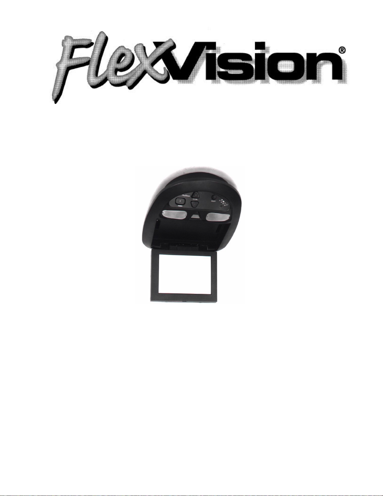
(LCM641TV Shown)
Flipdown LCD In-Vehicle
Television Entertainment
System
US Patent # D 413,856
Audiovox Specialized Applications, LLC
23319 Cooper Drive
Elkhart, IN 46514
219-264-3135
www.asaelectronics.com
Page 2
Warning:
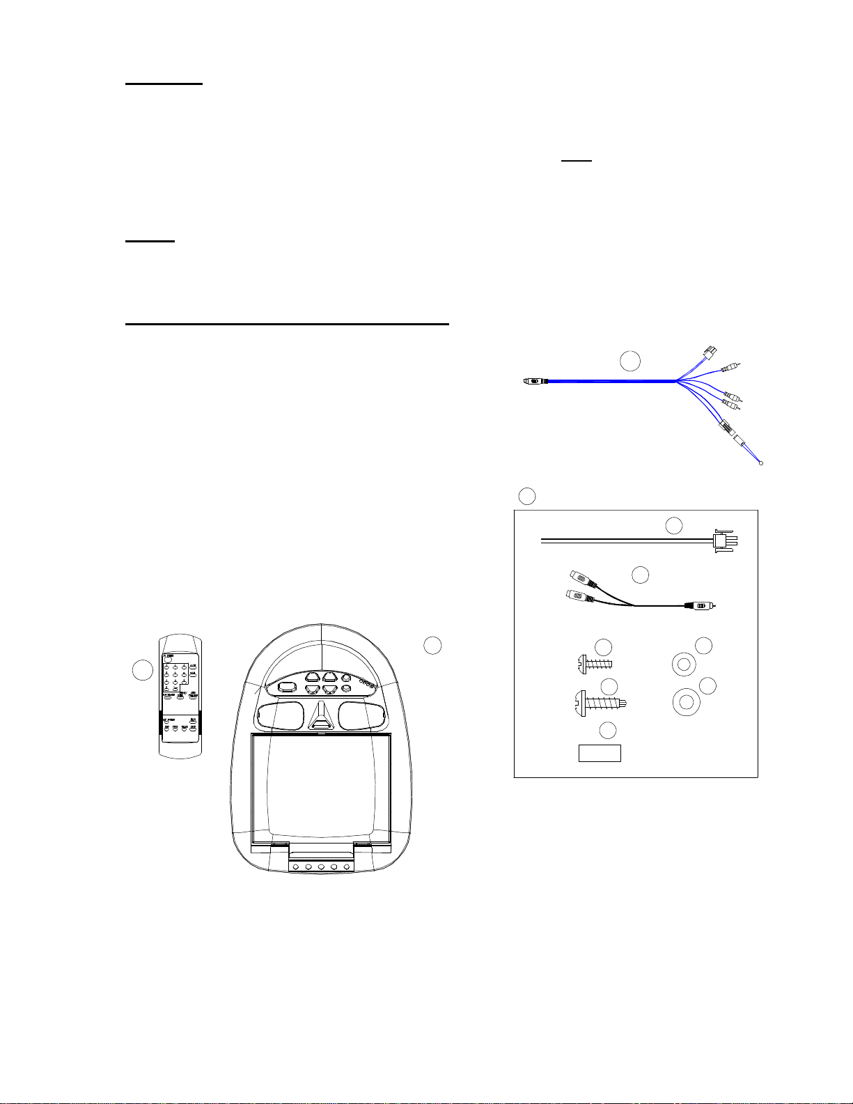
5) Remote Control (P/N 0892322)
It is unlawful in most jurisdictions for a person to drive a motor vehicle which is
equipped with a viewer or screen that is located in the motor vehicle at any point
forward of the back of the drivers seat, or that is visible, directly or indirectly, to
the driver while operating the vehicle. This product should only be installed to
the rear of the driver’s seat where it will not be visible, directly or indirectly, to the
operator of the motor vehicle.
Note:
Installation may require Mini-Console (trim ring), order number 1181300. Video
cassette p[layer must be purchased separately.
Materials Included in this Package:
1) LCM641TV/LCM641TVB Video pod- 1 pc.
2) Source Component Harness (P/N 8010730) –
1 pc.
3) Accessory Bag
3a) Power Harness (15ft). – 1 pc.
3b) Audio “Y” Patch Cord Adapter (P/N
0892165) – 1 pc.
3c) #4 x 3/8” Screws – 11 pcs.
3d) #4 Washers – 11 pcs.
3e) #6 x 5/8” Self-drilling Screws – 4 pcs.
3f) #5 Washers – 4 pcs.
3g) Spacers – 8 pcs.
4) Owner’s Manual/Installation Guide
3
2
3a
3b
5
Page 2 of 11
P/N 8010845
Rev.F Nov. 00
1
3c
3e
3g
3d
3f
Page 3
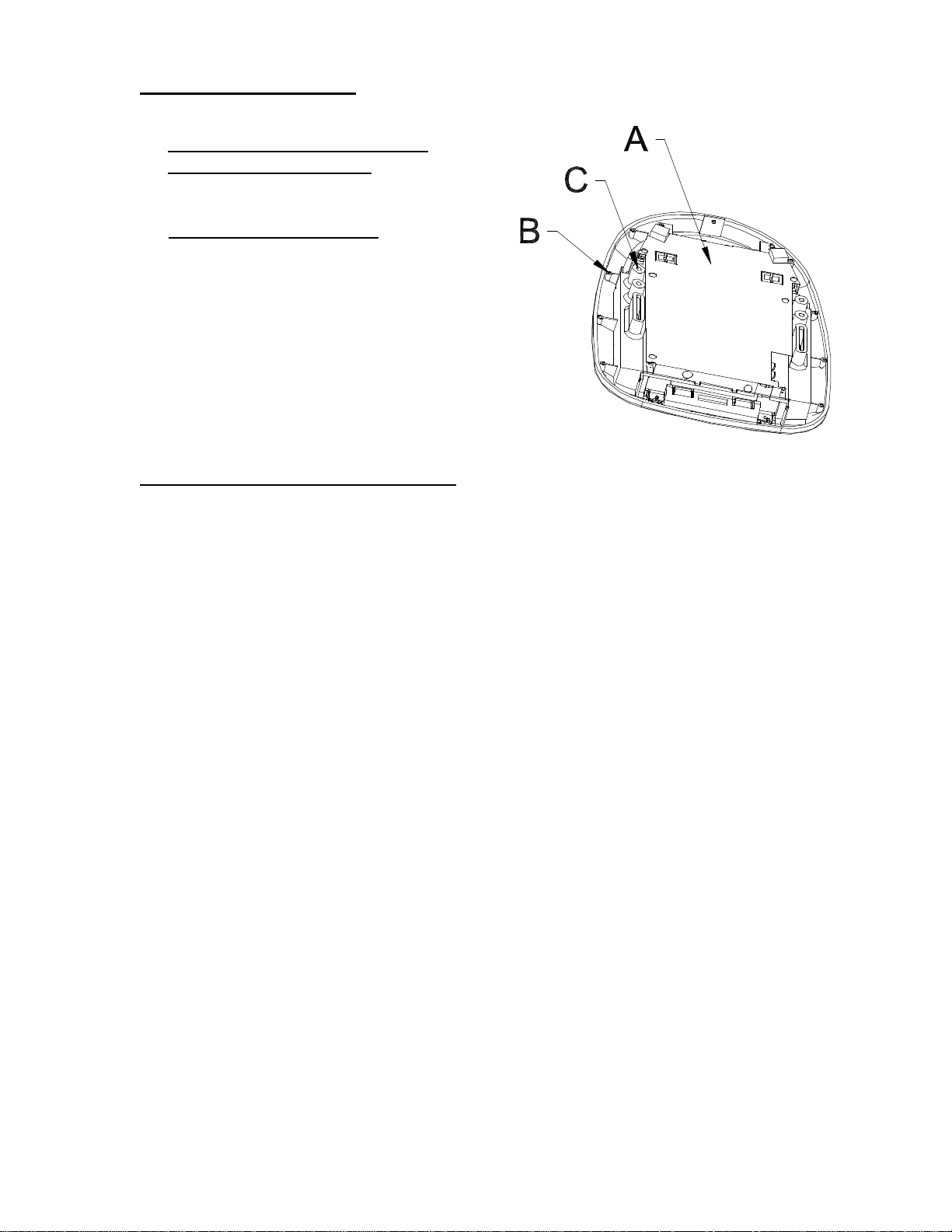
Rear Panel Features:
Figure 1
A – Shielded Tuner/ PCB Assembly
B – Perimeter Screw Bosses Use these
to affix the unit to various consoles/trim
bezels.
C – Mounting Screw Bosses Use these
to secure the unit to the roof structure of
the vehicle and/or console assembly
(optional)
General Installation Approach:
1) Before beginning installation, please refer to warning on manual page 10.
2) Decide upon system configuration and options that will be installed (ie: what
components, VCP, Tuner, Remote Headphones, 2ND VCP, etc.)
3) Review all manuals to become familiar with electrical requirements and hookups.
4) Decide upon mounting locations of all components and method of mounting.
5) Prep the vehicle by removing any interior trim necessary to gain access to
vehicle power hook-up point as well as all areas where interconnecting wire
harnesses will need to be located. If any access holes need to be cut into the
vehicle (headliner, other trim components, etc.) this should be done now as
well. Refer to Page 5.
6) Route the wiring harnesses throughout the vehicle as necessary. (Refer to
the wiring diagrams on pages 6 and 7 of this manual as well as the wiring
instructions for the individual components and accessory options being
installed). Be sure that all wiring is protected from sharp edges and is routed
in such a manner that it will not be pinched when all components and interior
trim are fully installed. Be sure to leave enough slack in the wiring at each
component to allow working room.
7) Remove all A/V system components from their packaging and place them
loosely at their respective locations.
8) Connect all components together (electrically) and verify proper operation of
all system functions. Note: This is best done both BEFORE and AFTER all
components have been permanently mounted.
9) After verifying proper operation of the system, proceed with mounting of each
component.
10) When all components have been mounted, recheck function of the entire
system again to ensure that no wiring was pinched or connected improperly
during final installation.
Page 3 of 11
P/N 8010845
Rev.F Nov. 00
Page 4

Tools Required:
- #2 Phillips Screwdriver
- #1 Phillips screwdriver
- Wire Strippers
- Utility Knife, or Shears
- Masking Tape
- Multimeter (to verify 12VDC and Continuity, do NOT use test light)
- Misc. electrical connectors (to connect to the vehicle power source… will vary
from vehicle to vehicle).
- Marker Pen
- Electrical Tape
- Video Tape (to verify function of the system after installation)
General System Configurations:
The following is intended to give a rough guideline of system configurations that
are possible with the LCM641 series flip down video pod:
System 1: Video Pod, VCP
- All wiring necessary is included with this package
- Headphones are connected into the headphone jacks on the pod
System 2: Video Pod, VCP, 2nd VCP (or other A/V component)
- Same as system 1, but extra Source Component Harness (P/N
8010730) must be purchased
Notes:
- All systems have a built-in game/camcorder prep (the A/V input jacks on the
video pod itself).
- To any system, there are a few audio output options that can be added as
follows:
a) Remote headphone jacks can be added to the system. Refer to
the wiring diagrams on pages 6 and 7.
b) Additional speakers and amplifiers can be added to the system
using the remote headphone outputs (see pages 6 and 7). Also
refer to the specifications in the Owner’s Manual (P/N 8010840).
- The LCM641 series video pods are only intended for an overhead, flip down
installation. They are not intended for seat back or any other type of
mounting. The hinging mechanism is designed for horizontal, flip down use
only.
- For audio over the vehicle’s speaker system an FM Modulator may be used.
Wireless headphones may be hooked up.
Page 4 of 11
P/N 8010845
Rev.F Nov. 00
Page 5

Vehicle Preparation:
1) Locate vehicle power source. Generally this is found near the vehicle’s fuse
block, which is usually (though not always) under the steering wheel area.
Locate an accessory hot circuit to tap into for video system power. Accessory
hot means a circuit that is +12VDC when the ignition key is in either the
“ACC’Y” or “Run” positions, and 0 Volts DC when the ignition key is removed
from the vehicle.
2) Mounting location and method for the individual components will vary from
vehicle to vehicle, so this manual will only focus on the installation of the
video pod itself and related console accessories.
3) Generally, the best location for the video pod is where the vehicle’s dome
light is traditionally installed (center of roof, just behind the front 2 seats). The
pod should be located in such a manner that it can be comfortably viewed by
the rear seat passengers in the vehicle. The pod should NEVER be located
in a position that would place it in within the driver’s field of view. This is not
only hazardous for driving conditions (as it creates a distraction to the driver),
but it is against the law in many states. Check your state laws.
4) Once pod location has been determined, there may be prep work required for
the headliner. Some of the steps that may need to be taken depending upon
your installation are:
a) Removing of the vehicle’s dome light.
b) The headliner MAY have to be cut out per the diagram below.**
c) If the mini-console is being used, it will have to be trimmed to fit
the contour of the headliner. Refer to page 8.
Note, steps a-c above are not required for all installations…. you may have to do
none, some, or all of these steps.
** IF your particular installation will require you to cut out the headliner, the box
that this kit came in can be used as a template. You can remove the shelf that
the video pod rests upon and trace the opening onto the headliner for cutting.
Figure 2
Page 5 of 11
P/N 8010845
Rev.F Nov. 00
Page 6

Wiring Diagram Hook Up Procedure:
assembly.
is plugged into RCA jack
1) Insert the circular mini-din
connector of the source
component harness
through wire tie loop on
the main PCB and into
mini-din connector on
main PCB (fig.3).
2) Pull wire tie loop tight and
cut off excess.
3) Connect power harness to
mating connector on
video monitor.
4) Connect power harness to
vehicle’s electrical system
by tapping into an
accessory hot line.
5) Verify all functions of
system before final
mounting of finished
Figure 3
Mini din connector
(Source Component
harness)
Wire tie Loop
Mini-DIN
Receptacle
Figure 4
Power Harness
Black: GroundBlack: Ground
Red: +12 VDC
Red: +12 VDC
(Accessory Cir.)
(Accessory Cir.)
TV antenna
TV antenna
(If applicable)
(If applicable)
Optional Remote Headphone StationsOptional Remote Headphone Stations
Stereo Headphone
Stereo Headphone
Jack
Jack
Stereo Headphone
Stereo Headphone
Jack
Jack
Power Harness
Item # 3a
Item # 3a
Spade
Spade
Terminals
Terminals
Spade
Spade
Terminals
Terminals
Spade
Spade
Terminals
Terminals
Power
Power
Connector
Connector
(2-pin)
(2-pin)
Green
Green
(Right+)
(Right+)
Black
Black
(Ground)
(Ground)
Gray
Gray
(Left+)
(Left+)
Antenna
Antenna
Connector
Connector
A/V Source definitions:
1 = Tuner
2 = VCP (left mini-din on main
PCB
3 = 2nd VCP (right mini-dIn on
main PCB for game, future
DVD, etc.
Note: AUX Input overrides 2
nd
VCP (DIN) Input when connector
Page 6 of 11
P/N 8010845
Rev.F Nov. 00
Page 7

Source Component Harness Hook-Up:
would plug into second Mini-Din
A second VCP or other A/V
component can be connected to
video monitor system using a
second source component harness
(purchased separately, P/N
8010730). This second harness
connector on main PCB as in
steps 1 and 2 above.
Video Out
(Yellow)
Right Out
(Red)
White RCA (Audio In Left)
Red RCA (Audio In Right)
Figure 5
Yellow RCA (Video In)
Source
Component
Harness
P/N 8010730
VCP
(Rear View)
Left Out
(White)
Power Connector
(4-pin)
IR LED:
Clean the IR Receiver Window on the front of the VCP.
Remove Adhesive Backing and Apply IR LED to IR
Window on the Face of the VCP.
"Y" Adapter
for use with
Non-Stereo
Installations
P/N 0892165
Page 7 of 11
P/N 8010845
Rev.F Nov. 00
Page 8

Mini Console Installation:
This page only covers special installation considerations for the mini-console
installation. If video pod is to be installed with a custom full sized overhead
console, skip to page 9 now.
If video pod is to be installed in a vehicle with mini-console (P/N 1181300), this
console may need to be trimmed to fit the contour of the vehicle headliner.
1) In this installation, the video pod is mounted directly to overhead cross
member in roof using mounting screw bosses (Item c on page 3). These
screw bosses should contact the cross member directly (ie: No gap between
the screw boss and roof structure). Also be sure that the screws (#3 on page
2) do not pierce outer roof skin when fully fastened into cross member. The
mini console is attached to video pod using perimeter screw bosses (Item b
on page 3). It is important that screws used in this installation are not over
tightened, and that the video pod and mini console are mounted in such a
way that assembly does not distort or bend when mounting screws are
tightened.
2) It is best to mount video pod to roof structure without mini console first. There
should be a gap between the headliner and outer flange of video pod. The
mini console should be cut to fill this gap. Apply masking tape to the outer
surface of the mini console where the cut will be made.
3) Mark cut to be made following the necessary contour of the roof. Suggested
method of marking is as follows:
a) First locate the narrowest point of mini console on masking tape. Be
careful to consider not only vertical location but fore-aft location.
b) Using the handle of a screwdriver, make a “transfer marking tool”. See
figure 6 below. Place the tool against the roof, and the marker against
the masking tape on the mini console. Trace cut to be made around
entire perimeter of mini console.
c) Cut mini console using a sharp utility knife or shears. Make cut in
several passes over marked line, each time cutting a little deeper. It is
not necessary to cut completely through plastic, cut only need be 50%
of the wall thickness of the plastic. Plastic will break cleanly at the cut
by bending cut back and forth several times.
d) Check fit of trimmed console and make any minor adjustments
necessary.
4) The mini console can be painted or covered with a material that matches
headliner before assembling mini console to the video pod.
5) The finished mini console should be attached to video pod, then attach
assembly to roof. See figure 7.
Page 8 of 11
P/N 8010845
Rev.F Nov. 00
Tape marker to screwdriver starting at
your mark for the lowest point, then
trace the contour of the roof
Lowest Point Mark
Figure 6
Headliner
Cut Line
Refer to figure 7 for detail on
attaching console to video
pod and video pod to vehicle
structure.
Page 9

Cut-Away view of Screw Bosses:
Roof Structure
Optional Spacers
3c
Screw Boss (ref "C", p3)
3d
Note, If longer
screws are
substituted, care
should be taken to
prevent piercing the
roof, and be sure
that pan head
screws and
washers are used
to prevent screws
from pulling though
the screw boss.
3e
3f
Perimeter Screw Boss (Ref "B", p3)
Figure 7
Console Flange
Nylon spacers have
been supplied in kit
to place under
mounting screws
and/or screw
bosses. They can
be cut to size as
needed.
Figure 7
Full Size Console Installation:
This page covers special installation considerations for full size, custom console
installation.
There are several “full size” custom consoles available for selected vehicles.
Some of these vehicles are the Chevy Suburban, Ford Expedition, and Dodge
Durango. These full size consoles incorporate several additional features, and
are particularity useful if the vehicle you are installing this system into already
has an OEM overhead console in the headliner.
Refer to the installation manual that comes with the console itself for complete
installation instructions. The diagram above shows a detail of the attachment of
the console to the video pod.
Page 9 of 11
P/N 8010845
Rev.F Nov. 00
Page 10

Accessory List
Description Part Number Price
AVT-988 9” Color Television with Remote (12V) AVT988 $320.00
AVT-597 5” Color Television with Remote (12V) AVT597 $320.00
AVT-1498 13” Color Television with Remote (12V) AVT1498 $350.00
AVP-7000 Video Cassette Player (12V) AVP7000 $270.00
BPA-501-12 4 Amp Adapter for use with AVT-988 9”
and AVT-1498 13” Televisions
AC2A- 2 Amp Adapter for use with AVT-597 5” TV
and AVP-7000 Video Cassette Player
Unified Remote Control 0892325 $45.00
VAC-21- 12 Volt Corded Vacuum VAC21 $35.00
AVF-1 12 Volt Rechargeable Flashlight AVF1 $25.00
HP-175 Headphones with Pivoting Ear Cup HP175 $11.75
HP-275 Headphones with Volume Control on Cord HP275 $16.00
HP-375 Studio Quality Headphones HP375 $14.00
Unlike household electronics, all of our products have been specifically designed
and tested for the mobile environment and are only available through ASA. To
order any of these products, please contact Audiovox Specialized Applications at
www.asaelectronics.com or 800-688-3135.
0891412 $45.00
0891436 $35.00
*Prices subject to change
Notes:
________________________________________________________________
________________________________________________________________
________________________________________________________________
________________________________________________________________
________________________________________________________________
________________________________________________________________
________________________________________________________________
________________________________________________________________
________________________________________________________________
________________________________________________________________
________________________________________________________________
________________________________________________________________
________________________________________________________________
________________________________________________________________
________________________________________________________________
________________________________________________________________
________________________________________________________________
Page 10 of 11
P/N 8010845
Rev.F Nov. 00
Page 11

For Installation Help, Call:
Audiovox Specialized Applications, LLC
1-800-688-3135
M-F, 8:00AM – 5:00PM
Page 11 of 11
P/N 8010845
Rev.F Nov. 00
 Loading...