

Page 1
AUDIOYOX
e HCTKONICS OORP
LCM5620PKG 5.6" Monitors
with
2 AudioA/ideo
Input Capability
Al-prOYOX
Installation and Operation Manual
Page 2

Important Notice
It is unlawful in most jurisdictions for a person to
drive a motor vehicle which is equipped with
a television viewer or screen that is located
in the motor vehicle at any point forward of
the back of the driver's seat, or that is visible
directly or indirectly, to the driver while
operating the vehicle.
Page 3
The Materials included In this package:
1 LCM5620PKG System Monitor (0ns Master. One Slave)
2. Master Remote Control Unit (MRCU)
3.
4.
S.
G.
7.
8.
9. Trim Ring
10.
Stave Remote Control Unit fSRCU)
13 Pin 4 Foot Din cable
System Main CaWo (SMC/
Master Housing v/tth built-in Master IR Transmitter (IRT456, CH A)
Slave Housing with built-in Slave IR Transmitter (1RT457. CH B)
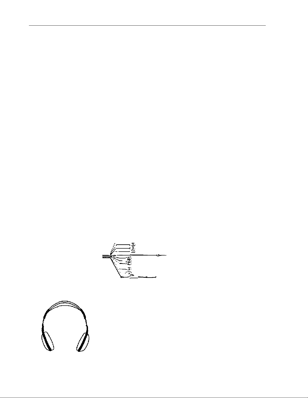
Dual Frequency IR Headphone set (2pcs)
Release Key
Optional Enhancements (not included, must be purchased separately)
1. FMM100, FM Modulator
1.
2.
CJ ■ —
(2pcs)
(Ipc)
(1pc)
(2pcs)
(Ipc)
(Ipc)
(Ipc)
(2pcs)
(2pcs)
6. 4 7.
i ^
*
__
s'
(\fr—-^1
S fm
------------------------
L-'?- r 'I
IQ.
zui
]
~
_
.
-1-
Page 4

LCM5520PKG SYSTEM OVERVIEW
1} The LCM5620PKG ís a versatile audío/video switching s>-stem, which includes two monitors, that
accept two Audio.Video inputs. A separate audio output is provided for connecting a FM Modulator to
the vehicie*s radio.
2) The Master Monitor is comprised of a 5.5" TFT LCD monitor that allows tlie user to select from two
A/V sources (Not Supplied). The housing has a built-in inferred audio transmitter (IRT 455. CH A) for
use v/ith the supplied two channel wireless headphones (CH A). The master monitor also has the
ability to select either audio source for output to an optional FM/Modulator (Audiovox FMM-100) to
allow audio playback through the vehicle radio. The built in IR repeater circuitry enables the user to
control Uie sources via remote cor\trol.
(NOTE: The VCP funclKons on the master remote are for use with Audiovox products only.)
3) Tlie slave monitor is identical to the Master Monitor, except that it can not control the AA/ sources, or
select the audio for the FM Modulator.
4) Tlie monitors v/iK show all of the functions including the FM selection (Master Only) with the compre
hensive OSD.
5) The LCM5620PKG System supplies Isvo IR Headphone sets. It offers excellent convenience for the
users compared to wired lieadphones. The headsets have an A-B switch that allows the user’s to
select the audio from either the master (CH A) or the Slave (CH B).
6) Using the IR codes, the Master Monitor will be able to respond only to the Master Remote Control
unit and the Slave will respond only to the Slave Remote Control unit. Each unit operates indepen
dently of the other,
(NOTE: The IR Repeater in this system may not svork with non-Audiovox components.)
VEHICLE PREPARATION:
Decide on the system configuration and the options that v/ill be installed (i.e.what components,
1)
VCP. DVD. TV Tuner, Video Game. Monitor, FM Modulator, etc.).
Read the manuals and gel familiar with the electrical requirements and connections.
2)
Decide on the mounting locations and methods of mounting the products.
3)
Prepare the vehicle by removing any interior trim necessary to gain access to the vehicle’s wiring as
4)
v/el) as all areas v/here interconnecting v/ire harnesses will be located. If any access holes need to
be cut Into the vehicle, headrests, or other trim components, this should be performed now. (Refer to
the Installation Procedure).
Run the wiring harnesses throughout the vehicle as necessary. (Refer to the Wiring Diagrams on
5)
page 7. as well as the wiring instnjctions for the individual components and accessory options being
installed) Be sure, that all the wiring is protected from sharp edges and is routed in such a manner
that it will not be pinched. v,fhsa it is fully iastalled. Besuro to leave enough slack in the wiring at each
component to allow sufficient working room.
Remove all the A'V system components from itieir packaging and then place them in the vohlde at
5)
their respective locations.
Connect all the components together (electrically) end vorih/ that the proper operation of all the
7)
system functions. NOTE: This is best done BEFORE the components are permanently mounted.
After verifying the proper operation of the system, proceed to mount each component.
8)
When all the components are iriounted, rechcck the function of Ihe entire sy.stem to be sure it is
9)
functioning correctly. Make sure that no wiring was pinched, or connected improperly during the final
installation.
-2-
Page 5
VEHICLE PREPARATION:
1) Locate an accessory power source (+12VDC present when the Ignition Key is in the accessory and
run positions. OVDC should be present, when the ignition key is in the OFF position). Generally, these
wires can be found at the ignition switch or fusebox. (NOTE: Ensure that the accessory power is
fused at the source. Failure to do so may result in vehicle wiring damage.) Ground the black wire \o
a chassis ground dose to the mounting location of AV sources.
The mounting method, and the location will vary from vehicle to vehicle, so this manual will only focus
2)
for the installation of the LCM5620PKG Master and Slave Monitors in the supplied configuration.
The best location for the LCM5620PKG System components is:
3)
a) Monilors: Headrest
b) Optional FM Modulator Near the car radio with the ON/OFF switch mounted on the dashboard
near the driver
c) System Main Cable: Under either seat where monilors are foccated.
Tools and Materials Required.
• Utility knife or box cuUer with sharp Wad*
• Sharpie'*^ marker or similar
• Tie Wraps
Remove the headrest from the vehicle for
easiest installation
Lay headrest on a flat surface
Center Iriiii collar on headrest as shown.
NOTE: Depending on the angle of the
headrest the trim ring and housing may be
mounted upside down.
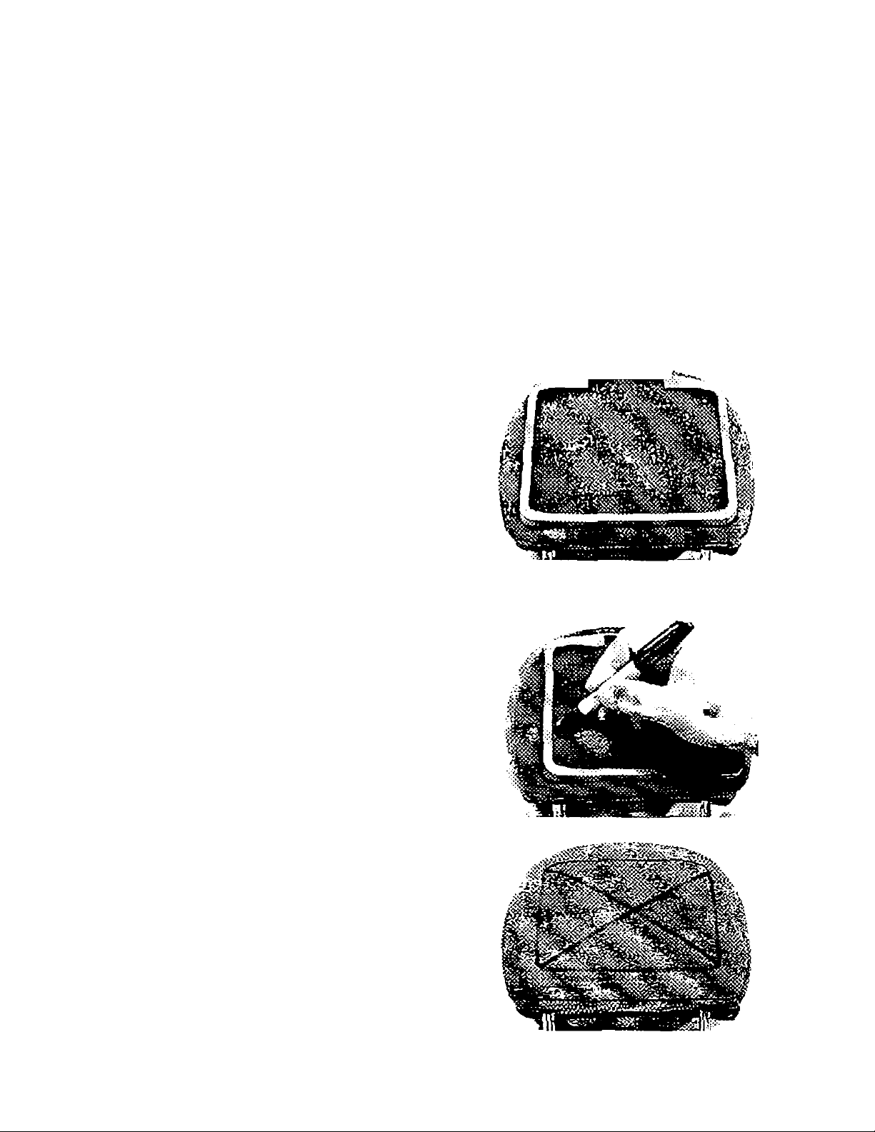
Using a Sharpie"^ marker or similar marking
pen. marV; headrest material along tne
interior of the trim collar.
Remove the trim collar and mark an “X" from
corner to comer as shown
-3-
Page 6

Using Vr\B utility knife, cut the headrest material along
the “X'* lines. Do not cur the material along the other
lines at this time.
This Will leave you with an ‘’X’’ cut as shewn.
Pull the flaps up and cut the foam beneath the
material fo the proper depth. Cut all four sides of
the foam,
Using your fingers, tear the foam out of the
headrest leaving a recess where the shell
will be inserted.
At this point you will need to install ihe
harness up through the area Into the recess.
It may be helpful to follow one of the posts
and tie wrap it to tl'\e post for restraint.
-4-
Page 7

Lay the flaps of headrest material down into the
recess and Insert the clamshell Into the recess.
Check for fit. If It does not fit properly, you may
need to remove some more foam.
NOTE: The clamshell will need to be secured
to the headrest, either by using tie straps,
screws, ect..
Remove the clamshell and insert the IR transmiller and plug into the IR transmitter board.
Reinsert the clamshell into the recess and
secure using lie wraps or saews
plug the remaining connector into the monitor.
Turn the monitor around and insert It into the
ciamshetl housing. Snap into place.
Conned the wiring to the video system and
test.
-b-
Page 8

13) MaKG sure that the Master/Slave Monitor Sv/itch (located on the bottom side of the Monitor) is set to
the appropriate posistion. Refer to die drawing belov;.
NOTE: If both units are set to "Master' or "Slave" at the same time the result will he improper function.
Master or Slave Monitor Switch
»
14) Thti supplied Release Key is for removing monitor from housing. Refer to the drav^ing below.
(l) IIUtIMWt
U.T
'iUJi
htlLKiri
i
0
twFMDHiTOn* •OVO<^.U.
0
TO iHi urwnonrrOM
-lOlBUiK; WESSTHCnCmStl'i»’
TOiXrr
fbtyj
•6-
Page 9

LCM5620PKG SYSTEM WIRING DIAGRAM
W*SttR«?'<rOB
tumj uikM
•SUffl .’Л>»ПОЯ
II rm roa.c*st£^^
1. ) Make sure Iho Master, and slave monitor have been installed properly, as described in the proce
dures as slated on pages 4,6. and 6.
2. ) ConnecUhe ГЛО 13 pin DIN terminals of the System Main Cable to the corresponding DIN terminals
of Master Monitor and Slave monitor on the bottom of the seats. Labe! the DIN terminal of System
Main Cable Master to connect to the Master monitor. The other DIN terminal of System Main cable
should be labeled as Slave and connect to Ihe Slave monitor.
3. ) There are Three RCA Jacks on the other end of the System's Main Cable, v/hich are labeled as Audio
#1 UAudioSt R/video #"1. These jacks need lo be connected to tiie respective AV plugs. Tlie AV cable
nome from AV source #1.
4. ) The IR repeater LED Uial is labeled LED#1 is utilized to connect to AV Source AlLED/il has an
adhesive that allov/s it to adhere to the AV Source #1 Remote Sensor Eye. Remove the backing
covering the adhesive and place LED #1 directly over the Remote Sensor Eye. NOTE: In some
cases you may need to offset the LED lo achieve proper operation, inside this LED cable there is a
2 pin JST terminal in series with the LED. Insert this terminal ю AV source #1 if it has a 2 pin JST type
socket that can accept a direct coded 38kHz signal.
5. ) Repeat item three and four for connecting AV source #2.
^.) Both sources can now be conVicIled witt-i the Master Monitor IR Repeater Circuit.
7. ) The System Main Cable also gels connected to the vehicle's accessory power terminal.
8. ) The two RCA Jacks on the system Main Cable, labeled as Audio L'Audio R for connecting Ihe FM
Modulator. Please refer to Ihe wiring instructions of the separately purchased FM Modulator {Audiovox’s
model FMM100 is recommended).
Page 10

líontrols on Master Monitor and Master Remote Control Unit
Master Monitor Panel Controls
o
ALDIOTOX
Power LED Indicator
POWER On / Off Button
Remote Control Sensor (IR)
MENU/ENTER Button
Select Up / Button
Select Down / Button
M (Master) / S (Slave) Monitor S'witch
Master Remote Control Unit Buttons
1
LCD : Power On / Off Button for Master monitor
2
VCP ■. Power On i Off Ballon for Auritovoy. VCP
3
SOURCE : Button for selection of AV )it 1 and AV #2
4
MENU/ENTER Button
5
- . Select Down i Button
6
+ ■ Select Up / Button
7
8
G
10
REW
FVvfD
PLAY
STOP
.Re’winds Tape
. Fast Forwards Tapo
. Plays Tape
.Stops Tape
I
5
7
to
-9-
Page 11

Controls on Slave Monitor and Optional Slave Remote Control Unit
Slave Monitor Panel Controls
power LED InOicalor
POWER on/Off Button
Remote Conlrol Sensor (IR)
MENU/ENTER Button
Select Up / Button
Select Dov^Ti / Button
M (Master) / S (Slave) Monitor Switch
Slave Remote Control Unit Buttons
1 LCD : Power On / Off Button for Slave monitor
2 SOURCE : Button for selection of AV and AV #2
3 Menu/Enter
4 -: Select Down / Button
5 + : Select Up / Button
-1U-
Page 12

OPERATION INSTRUCTION
1. Button Functions:
a) There are tour buttons on the front of the monitor; POWER. MENUi'ENTER.”A'’and "v".
b) POVsfER ‘ Pressing this button will turn the unit on.' off.
c) MENU/ENTER : Pressing this button. v.ili display the menu OSD. After opening the menu, it is
used as the Enter function.
d) With the menu displayed on the saeen you may then use the a or v buttons to select from:
Picture. Source, Audio (Master only) and Display off. When the appropriate item is highlighted
you may then press Iho enter button to access that function, then use the a or v to adjust or
switch the selected item,
NOTE: Tile above 4 buttons oro also located on the Remote Control Unit.
e) Source: This button Is only located on the remote control, and it will select between AV1 and AV
2. OSD
a) Press Ihe Menu/Enter button. OSD as below:
For using (he Master
MENU
PICTURE
SOURCE
AUDIO
DISPLAY OFF
b) Uso A or V buttons to highlight the AUDIO item, then press Menu / Enter button, OSD as below;
AUDIO
AUDIO 1
AUDIO 2
c) Use A or V buttons to select the audio for the FM Modulator (Color blue means that audio source
has been selected at Uie moment).
d) The Slave monitor cannot select the audio source, so the OSD AUDIO docs not appear in the
menu.
MENU
PICTURE
SOURCE
DISPLAY OFF
e) Select DISPLAY, then press the Mena'Enter button, this item v/ili change to "DISPLAY ON", that
means the source number selected will be displayed on the monitor until "DISPLAY OFF" Is
selected.
f) Highlight ihs SOURCE and press Menu/Enter button. OSD as below:
SOURCE
AVI
AV2
Then, you can use a or v buttons to select from AV1 or AV2. The Master monitor can also
operate the AV sources via the remote control sensor.
-11-
Page 13

g) If you select PICTURE. OSD below : (NTSC format, including TINT if video is PAL the OSD will
aulomaUcally change to PAL format (without TINT Hem in OSD).
NOTE: The unit will automatically select NTSC/PAL according to the input.
NTSC formal
•i> BRIGHTNESS 32
<> CO\7Py<S7 32
(¡T| COIOR 32
tint
on
PAL format;
BRIGHTNESS
cow RAST
Э
COLOR
GD
BESET
32
32
32
RESET
32 BRIGHI ness
^ 32 öfUGHINLSS ft
mil immilli
...........
innMlllillin
......................
h) In the above condition. If you highlight BRIGHTNESS and then pre?« Menu/Enler billion, OSD will
display as below:
Then you can use a or v biiUons to adjust It
i) TINT and RESET OSD p/ease refer fo befow picture :
00
TIN!
LiJ
^ ti
RESET
BRIGHTMESS 32
ft
CONTRAST
Э
COLOR
TINT
32
32
00
j) The OSD will automatically disappear if no buttons are pressed for 4 seconds.
•Ö* 52 BRIGHTNESS
-12-
Page 14

CAUTION
A
1. Do nol operate Ihe monitor at temperatures below 32''F (0''C) or above KWF (40’C).
2. Keep the monitor clean and dry.
3. Always seek qualified personnel to perform repairs. Never attempt your own repairs.
4. Do not drop the monitor or expose to strong impacts.
5. Do not expose to direct sunlight for extended nenods of time.
MONITOR SPECIFICATIONS
1, Type
2. Display Screen Si?:0 :
3. Resolulion
A. Pixels:
5. Back Light:
15. Power Source :
7. Power Consumption; 22W For 2 Monitors
8. Connection Terminals :
9. Operating Temperature: 32’F-104“F (O^C -AQ^C )
10. Storage Temperature:
11. Monitor Cabinet:
Dimensions
TFT Active Mntnx LCD
5.G inches (113.3 x 84.7mm) (W x H)
960 (W) X 234 (H)
224.640
Cold Cathode Fluorescent Lamp
+12 VDC
Power Input 12V. Video-'Audio Input Jacks (RCA) x2. IR Jacks x2,
Audio UTR Out (for FM)
_ i7e"F (-20“C- +80“C)
6.29 in x4.62 in X1-14 in (VVxHxD)
(160 X 115 X 29 mm)
12. Weight;
13. Video Format:
1.33 lbs (500g)
PAL, NTSC (Automatic Switching)
-13-
Page 15

-14-
Page 16

For Customer Service
Visit Ouf Website At
www.audiovox.com
Pfortud infonralion. Photos.
FAQ's Owner's Manuals
Copyright 2C01 Audiovox Electronics Corp, 150 Marcus Blvd. Hauppauge. NY 1175S
120-61^>1
 Loading...