

Page 1
JHD910
Owner’s Manual
JENSEN
MUTE
JENSEN
FM
AM/FM/WB RECEIVER
1
234
DISP
HEAVY DUTY
AM/FM
JHD910
AUX
WB
VOL+
AUDIO
TUN TUN
5
MENU
VOL-
SEEK
6
TIMER
SEEK
+
+
N
I
X
U
A
Page 2

JHD910
Thank You!
Thank you for choosing a Jensen product. We hope you will find the instructions in this owner’s
manual clear and easy to follow. If you take a few minutes to look through it, you’ll learn how to use all
the features of your new Jensen receiver for maximum enjoyment.
System Features . . . . . . . . . . . . . . . . . . . . . . . . . . . . . . . . . . . . . . . . . . . . . . . . . . . . . . . . . . 2
Installation . . . . . . . . . . . . . . . . . . . . . . . . . . . . . . . . . . . . . . . . . . . . . . . . . . . . . . . . . . . . . . . 4
Wiring . . . . . . . . . . . . . . . . . . . . . . . . . . . . . . . . . . . . . . . . . . . . . . . . . . . . . . . . . . . . . . . . . . . 6
Basic Operation. . . . . . . . . . . . . . . . . . . . . . . . . . . . . . . . . . . . . . . . . . . . . . . . . . . . . . . . . . . 7
Tuner Operation . . . . . . . . . . . . . . . . . . . . . . . . . . . . . . . . . . . . . . . . . . . . . . . . . . . . . . . . . . 9
Weather Band Operation . . . . . . . . . . . . . . . . . . . . . . . . . . . . . . . . . . . . . . . . . . . . . . . . . . . 10
Troubleshooting . . . . . . . . . . . . . . . . . . . . . . . . . . . . . . . . . . . . . . . . . . . . . . . . . . . . . . . . . . 11
Specifications . . . . . . . . . . . . . . . . . . . . . . . . . . . . . . . . . . . . . . . . . . . . . . . . . . . . . . . . . . . . 12
Features
Features of the Jensen JHD910 mobile audio system include:
• Waterproof
• uV and Corrosion Resistant
• Electronic US/Euro AM/FM Tuner
• 30 Programmable Presets (12 AM, 18 FM)
• Non-Volatile Memory for User Settings and Preset Memories
• 7-Channel NOAA Weather Band
• Weather Alert
• Auxiliary Audio Input
• Headphone Output
• 2-Channel Amplified Audio Output
• Backlit Controls with Selectable Illumination Color
• Daylight Readable Display
• Clock with 30-day Backup Power
•Work Timer
• Audible Beep ConfirmationTone
2
Page 3
JHD910
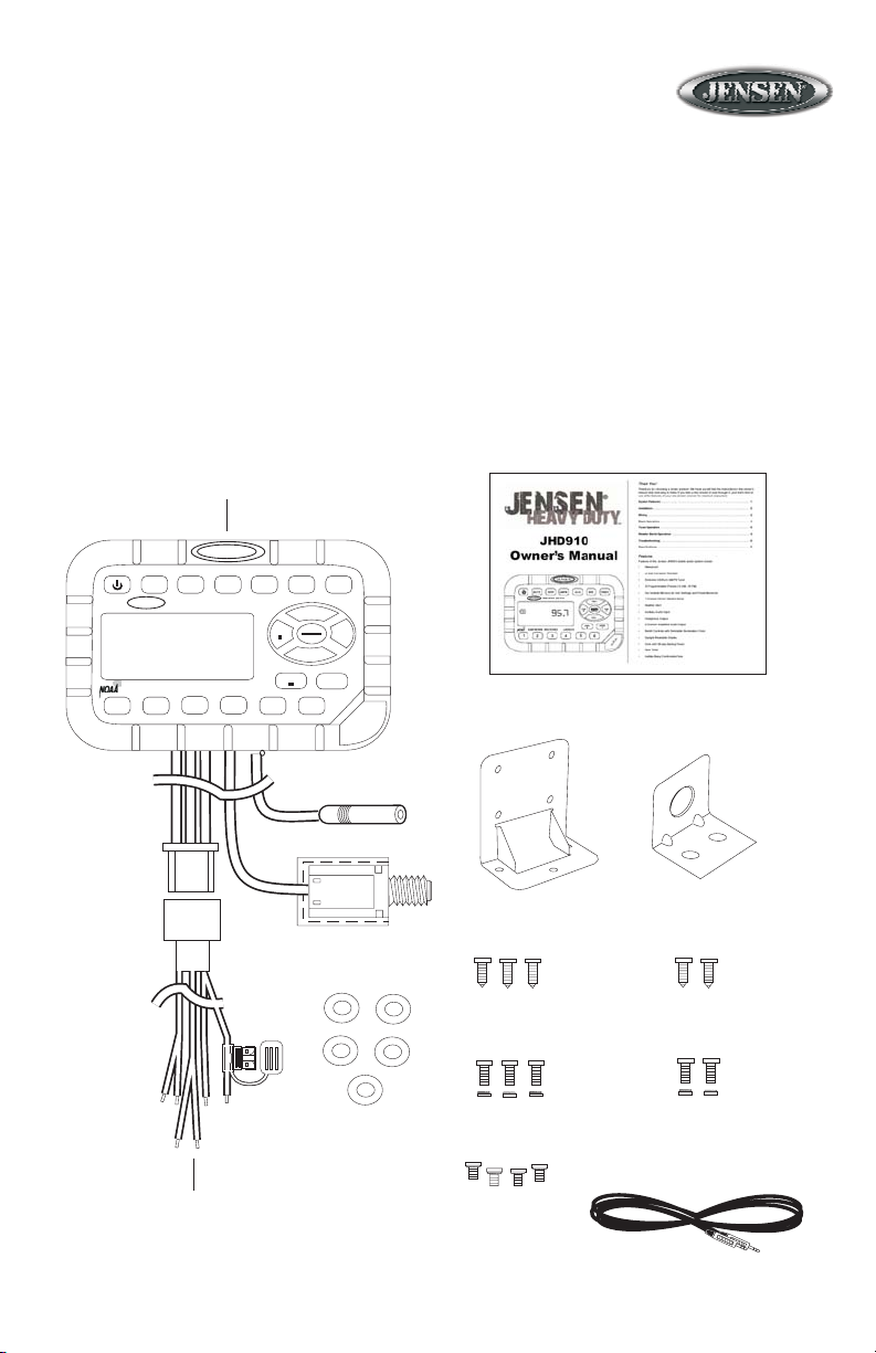
Package Contents
• JHD910 Radio
• Radio Mounting Bracket
• Headphone Mounting Bracket
• Five (5) 10-16 x 3/4” Stainless Steel PPH Screws
• Five (5) 10-32 x 5/8” Stainless Steel PPH Screws
• Five (5) 10-32 Stainless Steel Hex Nuts
• Five (5) #10 Stainless Steel Washers
• Four (4) M4 x .7 x 8MM Stainless Steel Hex Screws with Captivated Washers
• Wiring Harness
• Auxiliary Input Patch Cord
• Owner’s Manual
Owner’s Manual
JHD910 Radio
JENSEN
MUTE
JENSEN
AM/FM/WB RECEIVER
1
AM/FM
DISP
HEAVY DUTY
23456
JHD910
WB
AUX
TUN TUN
SEEK
AUDIO
TIMER
VOL+
MENU
+
VOL-
SEEK
+
N
I
X
U
A
Radio
Mounting Bracket
Headphone
Mounting Bracket
Wiring Harness
Washers
Self-Tapping
Screws (3)
Machine Screws
with Nuts (3)
M4 Machine
Screws (4)
3
Self-Tapping
Screws (2)
Machine Screws
with Nuts (2)
Auxiliary Input
Patch Cord
Page 4
JHD910
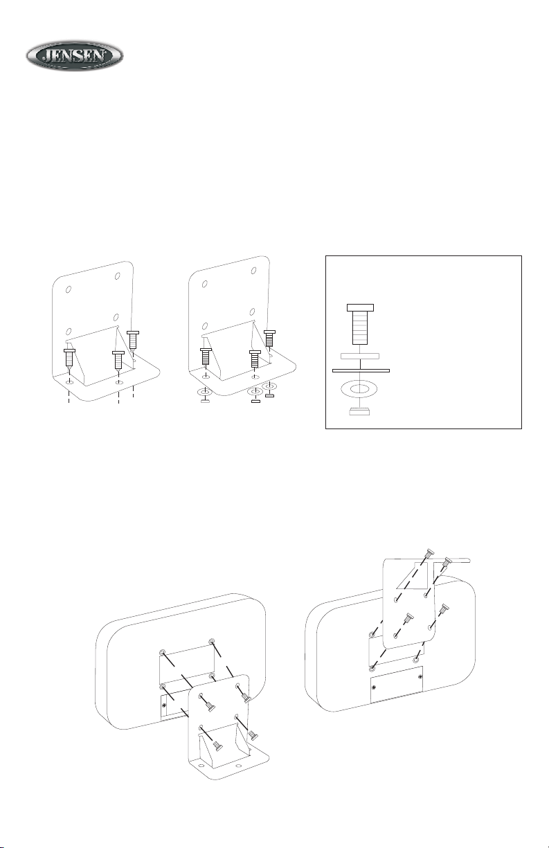
Installation
Mounting the Bracket
Two options are provided for mounting the bracket (self-tapping screws or machine screws with nuts) to
ensure a mounting option ideal for your mounting location. Avoid obstructing airflow to the rear cooling
fins on the radio.
Note: Mounting holes should be drilled to 7/32”. Before drilling the mounting holes, make sure
the area behind the panel where the holes are desired is clear of wires and fuel, vacuum and or
brake lines.
Mounting Stack
Mounting machine screw
Bracket metal
Vehicle mounting surface
Washer
Self-Tapping
Screws
(Hole size 7/32")
Machine Screws
with Nuts
(Hole size 7/32")
Nut
Attaching the Radio
Once the bracket is securely mounted, use the four included M4 machine screws to fasten the bracket
to the back of the radio. Alternately, the radio can be mounted directly to the instrument panel if access
to the rear of the instrument panel is available.
Regular
Mounting
Overhead
Mounting
4
Page 5

JHD910
Installation (continued)
Mounting the Headphone Bracket
Three options are provided for mounting the bracket (self-tapping screws, machine screws with nuts
or double-sided tape) to ensure a mounting option ideal for your mounting location. Alternately, the
headphone can be mounted directly to the instrument panel if access to the rear of the instrument
panel is available.
Note: Mounting holes should be drilled to 7/32”. Before drilling the mounting holes, make sure
the area behind the panel where the holes are desired is clear of wires and fuel, vacuum and or
brake lines.
Self-Tapping
Screws
(Hole size 7/32")
Machine Screws
with Nuts
(Hole size 7/32")
Mounting Stack
Mounting machine screw
Bracket metal
Vehicle mounting surface
Washer
Nut
5
Double-Sided
Tape
Page 6

JHD910
P
Wiring
The wiring diagram depicts all the wiring connections required for proper operation of the unit.
Antenna Connector
(Black Wire)
9-Pin Connector
(Male)
Left Speaker +
(White)
Left Speaker (White/Black)
Right Speaker +
(Gray)
Black Wire
Accessory
(Red)
Ground
(Black)
Right Speaker -
(Gray/Black)
PCB
Heat Shrink Tubing
3A FUSE
Note: Do not connect the red wire to a
constant power connection. It should be
connected to a vehicle connection with
switched power, such as IGN or ACC.
6
1/4”HEADPHONE OUTPUT
NUT
WASHER
RUBBER CA
VEHICLE PANEL
OR HEADPHONE
MOUNTING BRACKET
Page 7

JHD910
Basic Operation
1. Power
Press the power button (1) momentarily to turn the unit on or off. This button is also used to access
the version number of the software. To briefly display the software version on the LCD, press and
hold the power button for more than five seconds.
2. Mute
Press MUTE (2) to silence the audio output in tuner, weather band or auxiliary input mode. When the
audio output is silenced, “MUTE” will appear in the display. If the mute feature is activated when the
unit is turned off, the volume will default to the programmed turn-on level when the unit is turned back
on.
3. Display
Press DISP (3) momentarily to toggle the LCD display between function mode (showing tuner,
auxiliary input or weather band information, depending on which mode is currently activated) and
clock mode (showing the time).
4. Liquid Crystal Display
The Liquid Crystal Display (LCD) panel (4) displays the frequency, time and activated functions.
Basic Operation
2
1
MUTE
JENSEN
AM
AM/FM/WB RECEIVER
1
234
3
DISP
HEAVY DUTY
TIMER
4
JENSEN
AM/FM
JHD910
5a
WB
AUX
VOL+
AUDIO
TUN TUN
MENU
VOL-
SEEK
5
7
6
TIMER
+
SEEK
+
6
X
U
A
7a
8a
9
8b
7b
N
I
5b
Page 8

JHD910
5. Auxiliary Input Function
To connect a portable audio device (MP3 player, iPOD, etc.) to the JHD910, connect the headphone or
line level output of the device to the 1/8" auxiliary input jack of the JHD910 (5b) using the audio patch
cord (included). Pres AUX (5a) to select auxiliary input mode.
6. Timer
Press TIMER (6) momentarily to directly access timer mode. Briefly press TIMER to start the timer
function, and the “TIMER” icon will flash in the display. Press TIMER again to stop the timer, and the
“TIMER” icon will remain in the display (without flashing). Press the button again briefly to resume the
timer, or press and hold it for three seconds to reset it to zero and to remove the “Timer” icon from the
display.
7. Volume
Briefly press VOL+ (7a) or VOL- (7b) to adjust the volume up or down one step. Press and hold VOL+
or VOL- for more than one second to continuously adjust the volume level until the button is released.
The current volume level (0 to 40) will appear in the display when the volume is adjusted, returning to
the default display three seconds after the adjustment is complete.
8. Setting the Clock
To set the clock to display the current time, press DISP for more than three seconds to enter clock
setting mode, and the time will flash in the display. Press TUN- (8a) to adjust the hours or TUN+ (8b) to
adjust the minutes. When no adjustment is made for ten seconds, the time will be set and normal
operation will resume.
9. Audio and Menu Adjustment
Audio Adjustment
Press AUDIO/MENU (9) momentarily to step through the following audio adjustment options: Bass,
Treble and Balance (left to right). When the desired option appears in the display, press VOL+ (7a) or
VOL- (7b) to adjust that audio feature. When no adjustments have been made for three seconds, the
unit will resume normal operation.
Menu Adjustment
Press AUDIO/MENU for more than three seconds to enter menu adjustment mode and adjust any of
the menu options: When the desired option appears in the display, press VOL+ or VOL- to adjust that
menu option. When no adjustments have been made for three seconds, the unit will resume normal
operation. The following menu options may be adjusted using this feature:
• Beep Confirm (On or Off) - Determines if a beep will be heard each time a button is pressed.
• Operation Region (USA or Euro) - Selects the appropriate operating region.
• Clock Display (12 or 24) - Selects a 12-hour or 24-hour clock display.
• Display Brightness (Low, Mid or High) - Determines brightness level of the display.
• Backlight Color (Amber or Green) - Determines the backlight color of the unit.
• Turn On Volume (0-40) - Selects desired volume level for the unit to assume when turned on.
• WB Alert (On or Off) - Determines if the weather band alert feature is activated.
8
Page 9

JHD910
Tuner Operation
10. Select a Band
Press AM/FM (10) momentarily to directly access tuner mode from any other function mode. When the
unit is already in tuner mode, briefly press AM/FM to change between two AM bands (AM1 and AM2)
and three FM bands (FM1, FM2 and FM3).
Note: If the unit is programmed for European operation, the sequence will be MW1, MW2, FM1,
FM2 and FM3.
11. Manual Tuning
Press TUN- (11a) or TUN+ (11b) momentarily to tune the frequency one step higher or lower. Press
and hold TUN+ or TUN- for more than one second to tune continuously in the selected direction until
the button is released.
12. Seek Tuning
Press SEEK- (12a) or SEEK+ (12b) momentarily to automatically tune the frequency down or up to
the next strong station.
Radio and Weather Band Operation
MUTE
JENSEN
AM
AM/FM/WB RECEIVER
1
234
JENSEN
DISP
HEAVY DUTY
13
10
AM/FM
CH2
JHD910
14
AUX
WB
VOL+
AUDIO
TUN TUN
MENU
VOL-
SEEK
5
12a
9
TIMER
11a
+
11b
SEEK
+
6
N
I
X
U
A
12b
Page 10

JHD910
13. Preset Stations
Six numbered preset buttons (13) store and recall stations for each AM and FM band. To store a
station, select a band (if needed), then select a station. Hold a preset button for three seconds. The
current station will be stored, and the corresponding preset number will appear in the display. To
recall a station, select a band (if needed). Press a preset button momentarily, and the unit will tune to
the corresponding stored station.
Note: Preset buttons recall channels 1-6 on weather band and cannot be set by the user.
Weather Band Operation
14. Accessing the Weather Band
Press WB (14) to directly access the weather band mode from any other function mode.
What is the NOAA Weather Radio?
This is a nationwide system that broadcasts local weather emergency information 24 hours a day. The U.S.
network has more than 530 stations covering the 50 states as well as the adjacent costal waters, Puerto
Rico, the U.S. Virgin Islands and the U.S. Pacific Territories. Each local area has its own transmitting station
and there are a total of seven broadcasting frequencies used: 162.400MHz (CH1), 162.425MHz (CH2),
162.450MHz (CH3), 162.475MHz (CH4), 162.500MHz (CH5), 162.525MHz (CH6) and 162.550MHz (CH7).
How many stations can I expect to receive?
Since the broadcasts are local weather and information, the transmission power is usually very low (much
less than AM or FM stations) so you will usually receive only one station unless you are on the edge of two
or more broadcast signals. The most you will receive will be two or three, and that is rare.
Is it possible I won't receive any stations?
Depending on location, it’s possible you will receive a very weak signal or none at all. Also, similar to AM and
FM signals, weather band signals are subject to surrounding conditions, weather, obstructions of the signal
by hills or mountains, etc. If no NOAA signals are found/received, the “NO SIG” icon will flash in the display
and the tuner will scan all seven NOAA frequencies every 30 seconds.
How will I know I am tuned to the weather band?
When you select the weather band, the “WB” icon will appear on the display panel, along with the current
channel indication. Press TUN+ or TUN- to tune to each of the seven channels until you find the weather
band station broadcasting in your area.
NOAA Weather Alert
The Weather Alert function adds an additional level of user safety by automatically switching from the
current function mode to weather band mode for a minimum of 60 seconds if a NOAA warning tone (1050
Hz) is received/detected. If no additional warning tone is received for 60 seconds, the unit will switch back to
the last known function mode.
The Weather Alert function can be turned “on” or “off” by the Audio/Menu key, as described on page three.
When “ON” (default), the Weather Alert icon appears in the display and the weather tuner remains active,
even when the radio is turned off (as long as the power is still applied to the radio). If a weather alert is
issued, the radio will turn on and play the announcement. for 60 seconds, then turn back off and revert to
weather alert monitor mode.
If the Weather Alert function is set to “OFF”, no Weather Alert icon appears in the display. The radio will not
respond to any weather alerts when it is off and will not automatically switch to the weather band if an alert is
issued.
Note: If the unit is programmed for European operation, the WB function will be disabled.
10
Page 11

JHD910
Troubleshooting
Problem Cause Corrective Action
No power. Vehicle ignition switch is not
on.
The 3A fuse is blown. Replace the 3A fuse.
No reception Volume turned down too low. Adjust volume until sound is heard.
Wiring not connected properly. Check wiring connections.
Radio does not work Antenna cable not connected. Insert antenna cable firmly.
Volume too high or too
low when the radio is
turned on
LCD display is dark and
difficult to read
No WB function Programmed to “European” Program to “USA” (setup menu)
Weather alert does not
function
Note: Proper care and cleaning is essential to optimal operation. The JHD910 may be
cleaned with mild detergent/water mixture and a soft cloth to remove grease and grime. Do
not pressure wash directly on the radio.
Preset volume is set incorrectly Use the Menu adjustment (page
Radio too hot Turn radio off and allow to cool
Weather alert programmed to
“off”
If the power supply is connected to
the vehicle accessory circuits but
the engine is not moving, switch the
ignition key to “ACC”.
three) to change preset volume to
desired level
down
Program to “on” (setup menu)
11
Page 12

JHD910
Specifications
General
Power Supply Requirements. . . . . . . . . . . . . . . . . . . . . . . . . . DC 12 Volts, Negative Ground
Chassis Dimensions . . . . . . . . . . . . . . . . . . . . . . . . . . . . . . . . . 131.6 (W) x 47.5 (D) x 86 (H)
Loading Impedance. . . . . . . . . . . . . . . . . . . . . . . . . . . . . . . . . . . . . . . 4 -8 ohms per channel
Tone Controls . . . . . . . . . . . . . . . . . . . Bass (at 100 Hz), ±10 dB; Treble (at 10 kHz), ±10 dB
Current Drain. . . . . . . . . . . . . . . . . . . . . . . . . . . . . . . . . . . . . . . . . . . . . . . . 1.5 Ampere (max)
FM Tuner
Tuning range . . . . . . . . . . . . . . . . . . . . . . . . . . . . . . . . . . . . . . . . . . . . . . . . . . . . . 87.5-108.0
FM mono sensitivity . . . . . . . . . . . . . . . . . . . . . . . . . . . . . . . . . . . . . . . . . . . . . . . . . . . 1.5uV
Stereo separation @ 1 kHz . . . . . . . . . . . . . . . . . . . . . . . . . . . . . . . . . . . . . . . . . . . . . . >25dB
AM Tuner
Tuning range . . . . . . . . . . . . . . . . . . . . . . . . . . . . . . . . . . . . . . . . . . . . . . . . . . . . . . 522-1710
Sensitivity . . . . . . . . . . . . . . . . . . . . . . . . . . . . . . . . . . . . . . . . . . . . . . . . . . . . . . . . . . . <30uV
Weather Band
Sensitivity . . . . . . . . . . . . . . . . . . . . . . . . . . . . . . . . . . . . . . . . . . . . . . . . . . . . . . . . . . . . <1uV
Amplifier
Total system power . . . . . . . . . . . . . . . . . . . . . . . . . . . . . . . . . . . . . . . . . 15 Watts Maximum
Signal to Noise . . . . . . . . . . . . . . . . . . . . . . . . . . . . . . . . . . . . . . . . . . . . . . . . . . . . . . . >70dB
Specifications subject to change without notice.
Note: The manufacturer is not responsible for any radio or TV interference caused by
unauthorized modifications to this equipment. Such modifications could void the User’s
authority to operate the equipment.
This device complies with Part 15 of the FCC rules. Operation is subject to the following two
conditions:
1) This device may not cause harmful interference, and
2) This device must accept any interference received, including interference that may cause
undesired operation.
www.asaelectronics.com
© 2006 ASA Electronics Corporation
v.100506
12
 Loading...