

Page 1
INSTALLATION GUIDE FOR:
RADIO MODELS
IM-100/IM-200/IM-300
Printed In Korea 1S0-4O75 .
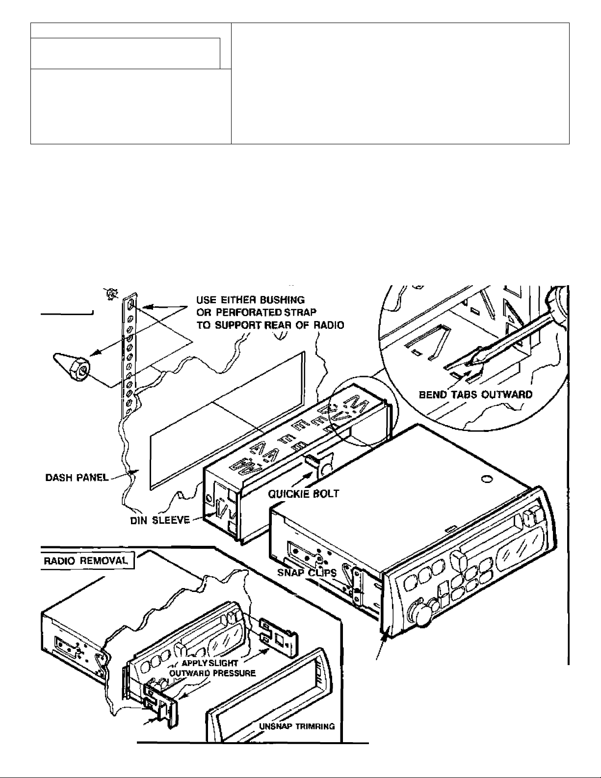
OJN MOUNTING (EXAMPLEiVOLKSWAGON)
SEE FIG. 1
1. Verify opening is within following dimensions;
A. Height 52mm-53mm (2 3/64'- 2 3/32")
S. Width fsamm-‘104mm (7 5/32" * 71/4*}
2. If opening Is less, carefull file to esoct size
required {DO NOT OVER FILE>
3. Remove din sleeve from radio arid place Into
opening,
4. Bend tabs outward to lock sleeve Into dash.
RG.1
5. Pre-wire radio. Slide radio into din sleeve until It
locks into place. Note: Use either near bushing
or perforated strap to sstMjre rear of radio.
RADIO REMOVAL {IF NECESSARY)
1, Unsnap trimring on face of radio.
2. Insert removal tool In slotted holes on sides of
radio uritil bottomed. Spread tools outward slightly
and pull radio toward you. Remove tools end
slide radio fully out.
HEMOVAl TOOt.
TRfMBEZEL (INSTALLED ON RADIO)
Page 2
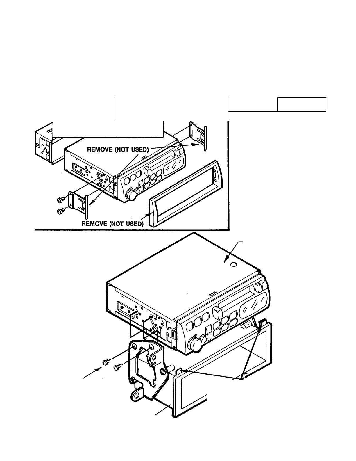
FACTORY STYLE INSTALUTION
(EXAMPLE:TOYOTA) SEE FIG. 2:
1. Remove factory radio dash panel to expose
sub-dash.
Remove radio bracket assembly from sub-dash.
Remove and discard radio dummy panel attached
to factory radio bracket assembly.
Install radio into bracket assembly using special
screws included with radio (see fig. 2)
CAUTION: Do not use longer screws or
damage to Internal parts of radio may occur
5. Re-install radio / bracket assembly after wiring
radio.
6. Replace dash panel.
RADIO REMOVAL (IF NECESSARY)
1. Reverse installation procedure. *
REMOVE (NOT USED)
REMOVE PARTS SHOWN-NOT USED
FOR FACTORY TYPE INSTALLATION
FIGURE 2
IM100/IM200/IM300 RADIO
SHORT SCREWS
(INCL.W/RADIO)
FACTORY BRACKET/POCKETASSEMBLY
NOTE: IN SOME CASES IT WILL
BE NECESSARY TO BREAK OFF
THE SMALL PLASTIC TABS ON MAP
POCKET IF THEY PREVENT FLUSH
FITTING OF RADIO
 Loading...