

Page 1

General Mobile Radio Service (GMRS) Transceiver
With Global Positioning System (GPS) Capability
Model GMR-GPS
Owner’s Manual
Released 10/19/01
Customer Service
1-800-290-6650
Page 2

INDEX
Warning .............................................................................................................................................. 3
Caution .............................................................................................................................................. 3
General Mobile Radio Service (GMRS) License ................................................................................... 3
General Features .................................................................................................................................... 4
The Global Positioning System (GPS) Network .....................................................................................4
The GPS Receiver.................................................................................................................................. 5
The GMR-GPS Unit ................................................................................................................................ 5
Getting to Know Your GMR-GPS Unit ..................................................................................................... 6
Operational Status Icon Definition ......................................................................................................... 7
Accessories ............................................................................................................................................ 8
Powering the GMR-GPS Unit ................................................................................................................. 8
Installing the Batteries ............................................................................................................................ 8
Using Rechargeable Batteries or Vehicle Cigarette Lighter Battery Eliminator .................................. 9
Operational Modes ................................................................................................................................. 10
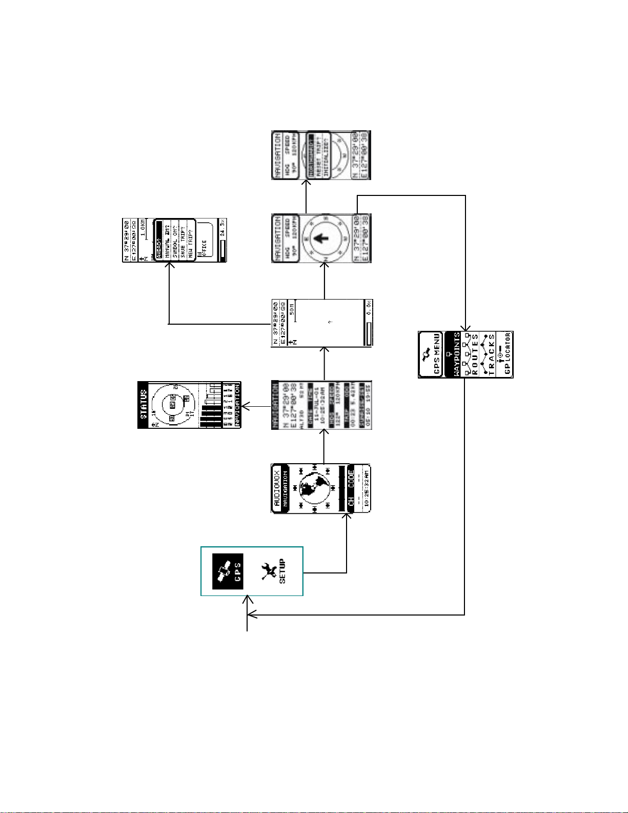
GMR-GPS Gateway Page Access to the Menu Pages .......................................................................... 11
Scrolling Through the Menu Pages ........................................................................................................ 12
GMR-GPS Operational Menu Flow Diagrams (Figures 1-5) ................................................................. 13
Setting Up the GMR-GPS Unit ............................................................................................................... 18
Adjusting the Volume .............................................................................................................................. 19
Setting Up the GPS Feature ................................................................................................................... 20
Paging Through GPS Functions ............................................................................................................. 2 1
Initializing the Global Positioning System Mode.................................................................................... 21
Selecting Pages ..................................................................................................................................... 21
Standby Pages ....................................................................................................................................... 2 1
GPS + Radio Standby Page................................................................................................................... 2 2
GPS Only Standby Page ........................................................................................................................ 22
Radio Only Standby Page...................................................................................................................... 2 3
The Gateway Page ................................................................................................................................. 2 3
Hot Key Menu Access ............................................................................................................................ 2 4
The Navigation Page .............................................................................................................................. 25
The Mark Waypoint Page ....................................................................................................................... 26
The MAP Page ....................................................................................................................................... 27
The POINTER Page ............................................................................................................................... 28
The GPS MENU Page ........................................................................................................................... 30
Taking a Trial Run ................................................................................................................................... 3 6
Let's Begin .............................................................................................................................................. 3 6
Mark Your Waypoint................................................................................................................................ 36
Let's Take a Short Trip ............................................................................................................................. 38
Going Home ........................................................................................................................................... 3 8
Locating Another GMR-GPS User ......................................................................................................... 3 9
GMR-GPS Radio Operation ................................................................................................................... 4 0
Radio Controls ....................................................................................................................................... 40
Accessing the Radio Setup Parameters ................................................................................................ 4 1
Explanation and Use of Radio Setup Functions ....................................................................................42
Accessing the Hot Key Radio Operating Modes .................................................................................... 43
Explanation of Hot Key Menu Use ......................................................................................................... 4 4
Notes For Good Communication ............................................................................................................ 46
Troubleshooting ...................................................................................................................................... 4 7
Technical Specifications ......................................................................................................................... 4 8
Main Channel Frequencies .................................................................................................................... 4 9
Continuous Tone Coded Squelch System Tone Frequencies (in Hz).................................................... 5 0
Warranty .............................................................................................................................................. 5 1
2
Page 3

WARNING:
• The GMR-GPS should be used as an aid in navigation. The unit is not intended to replace
basic navigational procedures and common sense.
• Because of errors inherent in the nature of the GPS system, the unit will not guide you to an
exact position or the precise indicated coordinates. However , under most circumstances, it
should be accurate to within about 100 feet.
• When using this device in a vehicle, use it only when the vehicle is stopped and it is safe to do
so. Operating the unit while driving is dangerous and could result in an accident or collision. It
is more important to keep your eyes on the road and hands on the wheel.
Do not operate the transceiver unless y ou are licensed to do so.
•
Remove the batteries from the unit if it is not expected to be used for long periods.This will
•
eliminate the possibility of chemicals leaking from the batteries and corroding the unit.
Av oid exposing the unit to w ater or extremes of temper ature.
•
Do not use this device in or near a mining f acility, which uses remotely triggered explosives
•
or in areas labeled “Blasting Area”. Premature or accidental detonation may result.
Do not attempt to modify or in any wa y increase the output of this tr ansceiver. Its output is
•
designed to meet the legal limits set by the FCC.
Do not use this device or change its batteries in potentially explosive atmospheres as sparks
•
in such areas could result in an explosion.
Turn your transceiver off wherever posted notices restrict the use of radios or cellular
•
telephones. Facilities such as hospitals may use equipment that is sensitive to RF energy.
T urn your transceiv er off on board aircraft when requested to do so .
•
Do not place your radio in front of a vehicle’ s air-bag. If the air-bag deploys, it could propel
•
the unit like a projectile causing bodily injury .
CA UTION:
• Never attempt to charge alkaline or dry cell batteries, as batteries may burst causing personal
injury and damage to the unit. When recharging batteries , use only Audiov ox-approved rechargeable batteries and charger. Use of the Audio vox charger with other brands of batteries is
not recommended. As battery charging times will vary with different brands, refer to the
manufacturer’ s instructions for charging other brands of batteries.
• Keep the antenna at least 1 inch (2.5 cm) aw a y from your head and body when transmitting.
Do not use your GMR-GPS transceiver with a damaged antenna.
• Replace the rubber cover over the headset receptacle when not in use.
General Mobile Radio Service (GMRS) License:
Use of this unit within the United States requires an FCC GMRS license. An individual 18 years
of age or older, who is not a representataiv e of a f oreign gov ernment, is eligible to apply f or a
GMRS system license. You will need two forms from the FCC; FCC F orm 159 and FCC Form
605 Main Form and Schedule F. You can find the forms online at: http: // www.fcc.gov /
formpage.html, or call 1-800-418-3676.
3
Page 4

GENERAL FEATURES
GPS FEA TURES
- 128 x 64 Dot Pixel LCD Display
- LCD Backlight for Night Operation
- Mode Icons for GPS + RADIO, GPS ONLY and RADIO ONLY
- 8 Parallel Channel Satellite Receiver
- GPS Partner Locator (GP LOCA TOR)
- Stores 10 Routes with Up to 20 W aypoints Each
- Provides 5 Tracks
- Map and Pointer Displa ys Provide:
Latitude and Longitude
Current/Ave rage/Maximum Speed
Bearing and Heading
Date and Time
Sunrise and Sunset
GMRS FEA TURES
-
15 GMRS Channels (7 Shared FRS)
- 38 Privacy Codes (For Each Main Channel)
- Built-In Hands-Free VO X Capability
- Up to 5-Mile Range
GENERAL FEA TURES
-
Requires 4 AA Alkaline Batteries or Type NiMH or other type
Rechargeable Batteries (Not Included)
- Fold-Down GMRS Antenna
- Swivel Belt Clip
THE GLOBAL POSITIONING SYSTEM (GPS) NETWORK
GPS is a world-wide radio navigation system based on a group of about 26 satellites and their
associated ground stations. A GPS receiver uses signals from the satellites to calculate its position
and altitude. The basis of GPS operation is triangulation, and the receiver uses the travel time of
radio signals from the satellites to calculate its distance from each one using a technique called
“pseudoranging”. It can then create lines of position.
The satellites transmit two types of signals called “C/A” (coarse/acquisition) and “P” (precision). The
latter are encrypted and can only be used by military GPS receivers. As with all other GPS units
available to the public, the GMR-GPS makes use of the C/A signals to establish position and
altitude. The accuracy of a displayed position varies with a number of factors including time .
4
Page 5

Generally, the position displayed by a GPS receiver using the C/A signals should be accurate to
within 100 feet, and for 50% of the time it should be accurate to within about 40 feet. It is normal for
the displayed position to “wander” slightly over time. For the same reason, the altitude displayed by
a GPS receiver will also vary slightly.
It is important to understand that such variations are inherent in GPS and do not indicate a fault in
the receiver . Remember also, that GPS is operated by the DOD and is subject to military requirements. There is no guarantee that signals will always be a vailable, or that an y display ed position or
altitude will be accurate.
THE GPS RECEIVER
A GPS receiver such as the GMR-GPS uses the C/A signals from the satellites to determine its
position on earth. Signals from three satellites are needed to provide an unambiguous position fix,
with reliable altitude indications requiring a fourth. In most circumstances, a GPS receiver will be
able to receive signals from more than four satellites and can decide which it will use to give the
best position.
Signals from GPS satellites are relatively weak and are easily blocked by obstacles or local screening. GPS receivers may not work well indoors, in vehicles or underneath trees or foliage. For best
results, the receiver should be able to “see” as much of the sky as possible.
THE GMR-GPS UNIT
The Audiovox GMR-GPS provides you with the features of a precise hand-held GPS unit designed
for general purpose locating and navigation. Not only can it determine your actual position, it can
also guide you to a destination by establishing and storing waypoints to mark the trail or route, and
allow you to return to your original starting point.
But what makes this unit unique, is the incorporation of GMRS capability, whereby your position
can be transmitted to another GMR-GPS unit, thereby allowing another party to know your exact
position, your intended route, and how long it will take you to arrive at that position.
By including three modes of operation, your GMR-GPS can act as a mobile radio transceiver only,
as a GPS unit only or as a combination of the two technologies for navigation and communication
purposes. The GMR-GPS incorporates the following f eatures and capabilities:
• WAYPOINTS: The unit provides 150 waypoints with user-selected names and graphic
symbols.
• ROUTE: Lets you navigate up to 10 routes with 20 waypoints in each route.
• TRACKS: Provides an automatic track log using five saved tracks; these tracks allow
the user to locate the beginning and end point of each track.
• MARK: Allows the user to save and transmit his/her location to other GMR-GPS units
tuned to the same channel (up to a distance of approximately 5 miles).
• GP LOCATOR: Allows the user to receive and store position coordinates of other
GMR-GPS users.
5
Page 6
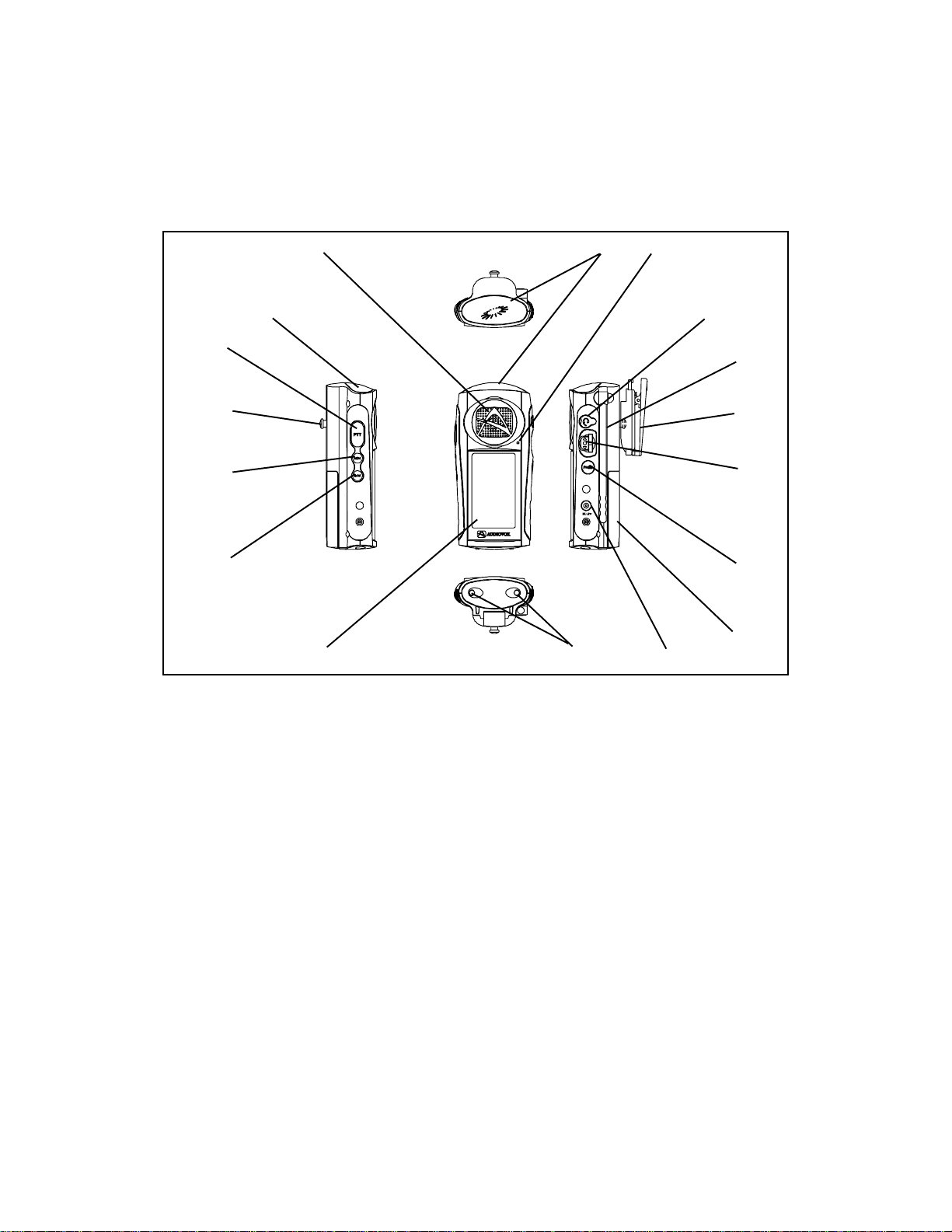
GETTING TO KNOW YOUR GMR-GPS UNIT
34
(TOP)
2 (REF)
2
1
16
15
14
13
1. Push-to-T alk Button (PTT) Button: Used during GMRS radio operation when tr ansmitting
voice signals and call tones.
2. Global Positioning System Antenna: Provides reception of GPS satellite signals to
determine location. The unit should be held upright to maximize received satellite inf ormation.
3. Built-In Speaker: Provides receive audio during GMRS operation.
4. Built-In Microphone: Accepts voice/audio input signals when transmitting during GMRS
operation.
5. External Speaker/Microphone Jack: Accepts external microphone/speaker plug for
use during GMRS operation.
6. GMRS Retractable Antenna: Provides GMRS transmit/receive operation when extended.
7. Belt Clip: Allows unit to be carried on a belt or clothing when attached to the clip.
8. Wheel Key: Spring-loaded center position switch.
(BOTT OM)
12
5
6
7
8
9
10
11
Up/Down movement:
a. Increase/decrease volume level during radio operation.
b . Cursor up/down movement for highlighting menu items for selection.
Press-to-Enter:
a. Selects menu item to be changed or modified.
b . Confirms data entry or menu selections.
6
Page 7
9. Page Button (P A GE): Scrolls sequentially through menu pages in the f orward direction,
and also provides access to a shortcut display for easy acquisition of main GPS displays.
10. Battery Compartment Cover: Allows access to four AA batteries when removed.
11. DC6V Jack: It accepts a DC-to-DC vehicle cigarette lighter battery eliminator adapter.
12. Battery Charging Contacts: Provide in-unit charging of batteries when unit is placed in
charging stand.
13. LCD Display: Displays the various pages, menus, and modes of operation.
14. Power On/Off/Mark Button ( /M): Pro vides a means of turning the unit on and off;
during GPS operation, this button is also used to mark a current position for save purposes,
or for sending your location to another unit during tracking/GO T O operation.
15. Monitor (MON) Button: Provides a means of temporarily bypassing the squelch setting
and play all signals on a given GMRS channel.
16. Belt Clip Attachment Stud: Allows unit to be attached to the belt clip.
Operational Status Icon Definition
This icon appears during GMRS/GPS operation when
an audio or location radio signal is being transmitted.
During GMRS operation, this icon indicates the
relative strength of a received radio signal.
This icon indicates that a user is contacting you with a
unit that is set to the same channel and CTCSS code.
This icon appears during GMRS operation to
indicate the channel scan mode has been activated.
This icon appears during GMRS operation to
indicate the Priority Channel Scan mode has been
activated.
This icon appears during GMRS operation to
indicate the V OX mode is activated.
This icon appears during GMRS operation to
indicate the Key Lock mode is activated.
This icon appears when the RADIO ONLY or
RADIO + GPS mode is operational.
This icon appears when the GPS or RADIO + GPS
mode is operational.
This icon indicates the current strength of the
battery.
7
Page 8
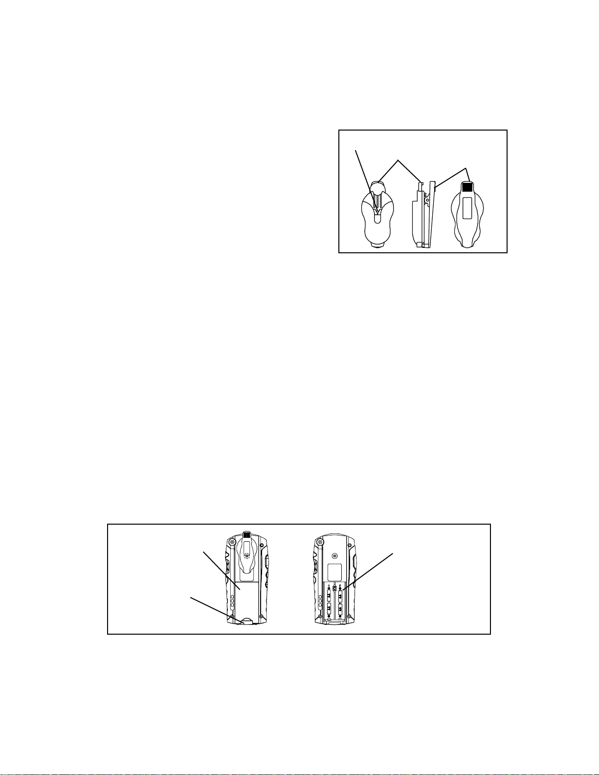
Accessories
SUPPLIED:
(1) Belt Clip
(1 ) Carrying Case (P/N GMRGPS-CS)
SPRING
CLIPS
CLIP
RELEASE
TAB (PRESS
DOWN)
SPRING
LOADED
BELT CLIP
OPTIONAL:
(1 ) Desktop Charger (P/N GMRGPS-SC) and
AC/DC Wall Adapter (P/N GMRGPS-W A)
(1 ) V ehicle Cigarette Lighter BatteryEliminator
(DC12V -to-DC 6V) (P/N GMRGPS-BE)
(1 ) Car Mounting Bracket (P/N GMRGPS-CB)
(1 ) Headset (P/N FRS-BHST)
Belt Clip Accessory
(1 ) Set of Rechargeable Batteries
Po wering the GMR-GPS Unit:
Your GMR-GPS unit operates on four AA batteries. Alkaline batter ies will provide slightly better
performance than rechargeable batteries. Only Audiovox-approved rechargeable batteries can be
recharged in the unit using the optional charger. This will ensure optimum performance for the
GMR-GPS. Use of the Audiovox charger with other brands of batteries is not recommended, as
battery charging times will vary. Refer to the manufacturer’ s instructions f or charging other brands
of batteries.
Installing the Batteries:
Installing batteries in the GMR-GPS unit is straightforward as shown in the illustration below .
1. Simply unlatch the cover clip at the bottom rear of the unit and lift off the battery compart
ment cover.
2. Remove the four discharged batteries, if present, unless the unit is being used for the first
time.
3. Install four rechargeable AA batteries, or install Alkaline batteries, if desired. Carefully note
battery polarity as marked within the battery compartment.
4. Slide the battery compartment cover in place; swing up the cover retaining clip and snap it
into position.
BA TTER Y
COMP ARTMENT
COVER
COVER
CLIP (SWING
DOWN)
BA TTER Y
COMP AR TMENT
(OBSERVE
POLARITY)
Battery Installation and Removal
8
Page 9
The following guidelines will improve performance and provide longer operating times for the
GMR-GPS unit:
1. Do not mix old and new batteries.
2. The use of alkaline-type batteries is recommended to provide the longest operating time.
3. Do not mix alkaline, standard (carbon-zinc) or rechargeable (NiMH) batteries.
4. If the unit is not to be used for an extended period of time, remove the batteries. Old or
leaking batteries can cause damage to the unit and will void the warranty.
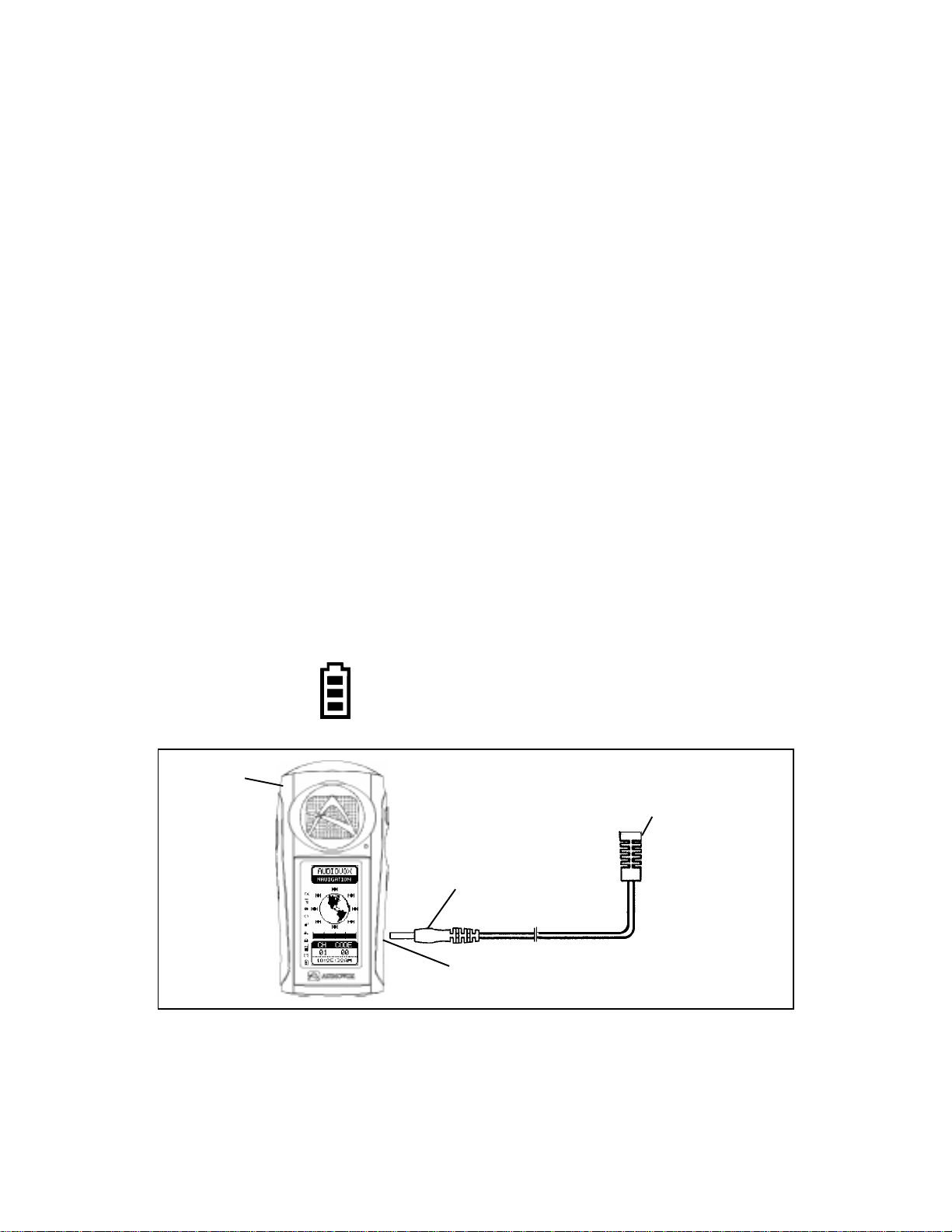
Using Rechargeable Batteries or Vehicle Cigarette Lighter Battery Eliminator:
When rechargeable batteries are installed in the GMR-GPS unit, they can be recharged by placing
the unit on the optional charging stand, Part Number GMRGPS-SC.
CAUTION: The optional charging stand is intended for use only with Audiovox-approved rechargeable
(NiMH) batteries (P/N GMRGPS-BT). Avoid ov ercharging the batteries, or else battery
life will be shortened.
In addition, the unit can be operated from a 12 Vdc source (such as a v ailab le from a car cigarette
lighter receptacle) only by connecting the optional vehicle cigarette lighter battery eliminator to the
DC6V jack on the lower right side of the unit. When connected for operation in this manner, the
batteries are bypassed and are no longer used to power the unit. The battery charge indicator icon
displays the battery charge level.
CAUTION: Direct application of 12 Vdc will cause damage to the unit.
GMR-GPS
UNIT
Full Battery - Three segments illuminated.
Low Battery - One segment illuminated.
INSERT INTO VEHICLE
12 VDC CIGARETTE
LIGHTER RECEPTACLE
ADAPTER
PLUG
DC 6V
JACK
V ehicle Cigarette Lighter Battery Eliminator Setup
9
Page 10
OPERATIONAL MODES
The GMR-GPS is capable of three modes of operation; namely, RADIO ONLY, GPS ONLY or
GPS + RADIO. The desired mode can be selected using the Setup menu once the unit is turned on
and in the standby mode.
Po wer On/Off ( ) and Mark (M) Button (14)
1. Press and hold the power On/Off ( ) button f or at least 2 seconds. You will hear a confirming
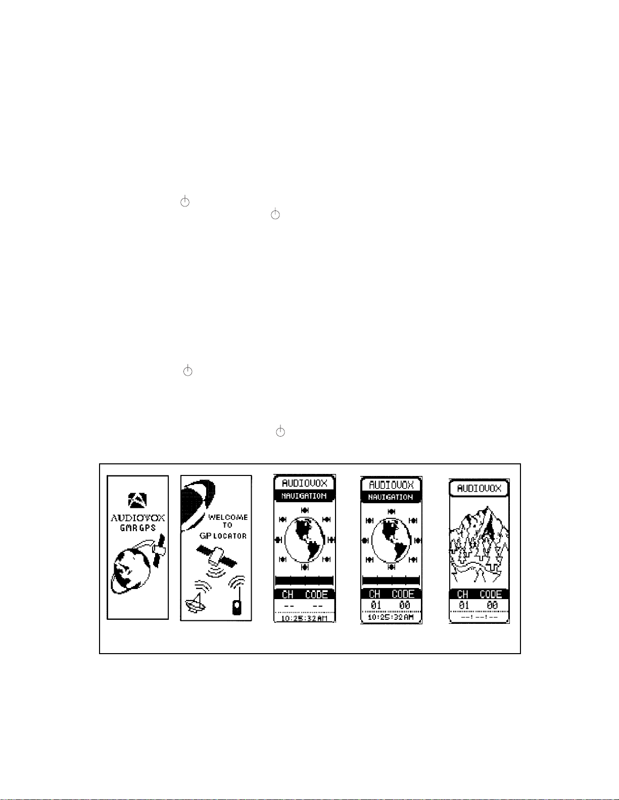
beep to indicate the unit is on. In addition, at turn-on, the Audiovox logo display appears
on the LCD for about 2 seconds, follo wed b y the WELCOME TO GP LOCATOR display. A
short beep and melody then sounds and the standby display appears.
NOTE: If the unit was previously in a radio only mode (GMRS) , the unit displays the radio
standby page and enters the monitor receive mode. The radio channel and Coded
Tone Controlled Squelch System (CTCSS) code appears at the bottom of the
display . If the unit was pre viously in a GPS mode (GPS ONLY or GPS + RADIO), the
top of the display indicates whether or not the unit is ready for NAVIGA TION,
SEARCHING to enter the GPS domain, or in the SLEEP MODE (no satellite signals
received for at least 7 minutes, and no reinitialization of the search mode).
2. Pressing the /M button for longer than 1.5 seconds will turn off the unit.
3. In GPS mode, a Gateway page can be accessed from any of the six primary menu display
pages; this page provides quick access and/or return to any other primary menu page.
NOTE: Momentarily pressing the /M button while the unit is on will access the Mark
function, which is used during GPS operation to keep track of waypoints and route
information (discussed later in detail in this manual).
LOGO DISPLAY
WELCOME TO GP
LOCATOR DISPLAY
GPS ONLY
STANDBY DISPLAY
GPS + RADIO
STANDBY DISPLAY
RADIO ONLY
STANDBY DISPLAY
Po wer On Displays and Standb y P ages
10
Page 11
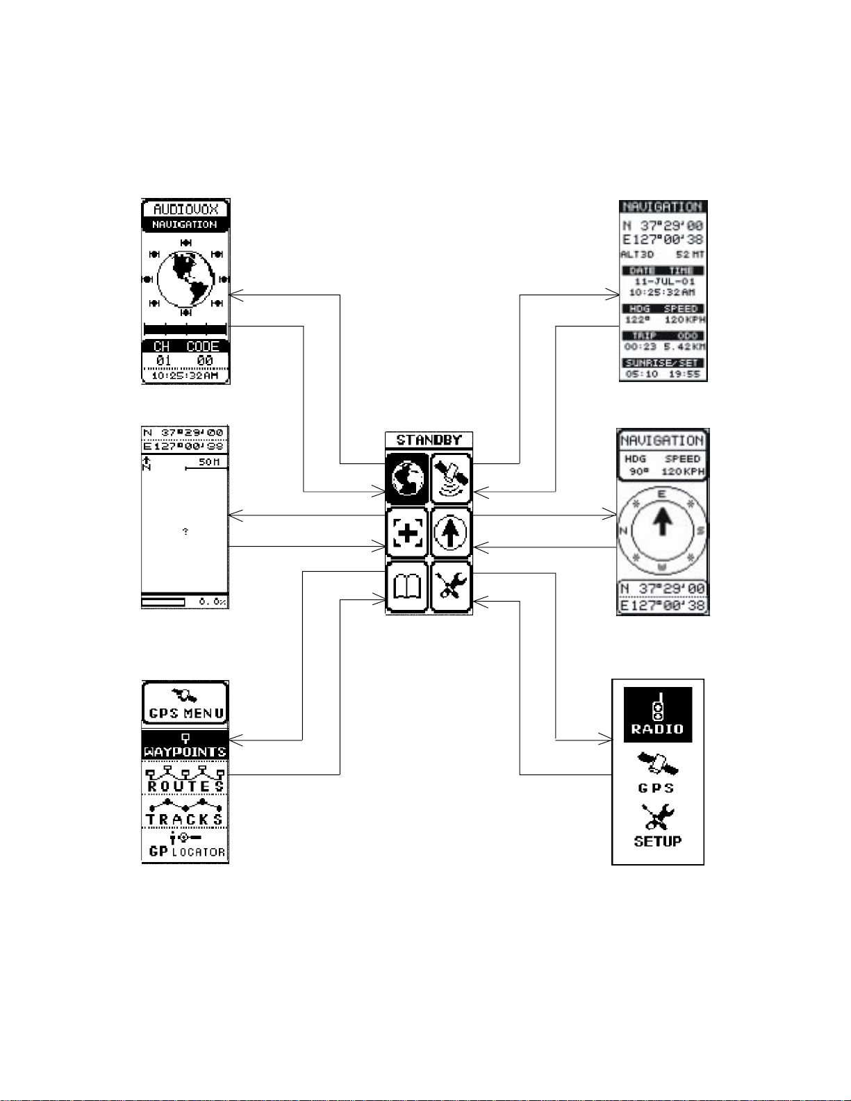
STANDBY PAGE
NA VIGATION
PAGE
PRESS ENTERPRESS ENTER
MAP PAGE
MENU PAGE
PRESS/HOLD P AGE
PRESS/HOLD P AGE
PRESS ENTER
PRESS/HOLD P AGE
POINTER PAGE
PRESS ENTERPRESS ENTER
PRESS/HOLD P AGE
PRESS ENTER
GATEWA Y PAGE
SETUP PAGE
PRESS AND HOLD PAGE TO ACCESS GATEW A Y DISPLA Y FROM ANY
PRESS/HOLD
PAGE
PRIMARY DISPLA Y P A GE; MOMENTARILY PRESS PAGE TO ACCESS
THE NEXT PRIMARY DISPLA Y P A GE.
USE UP/DOWN WHEEL KEY TO HIGHLIGHT PRIMARY PAGE ICONS ON
GA TEWAY DISPLAY; THEN PRESS
ENTER TO ACCESS PRIMARY DISPLA Y P A GE.
PRESS/HOLD
PAGE
GMR-GPS Gateway P age Access to the Men u P ages
11
Page 12
Scrolling Through the Menu Pages:
1. With the unit in the GPS ONLY or GPS + RADIO standby mode, pressing the PAGE button
will permit scrolling through the primary radio/GPS menu pages.
a. Navigation Page
b. Map Page
c. P ointer Page
d. GPS Menu Page
e. Setup Page
f. Standby P age
2. With the unit in the RADIO ONLY standby mode, pressing the PAGE button permits scrolling
through the radio menu pages.
3. The flow diagrams on the following pages illustrate the paths through the various setup
menus for Radio , GPS and General unit functions. Depending on the Setup mode (RADIO
ONLY, GPS ONLY or GPS + RADIO) certain displays and/or menus ma y or may not
be available.
GPS + RADIO
STANDBY PAGE
NAVIGATION
PAGE
MAP
PAGE
POINTER
PAGE
GPS MENU
PAGE
SETUP
PAGE
PRESS ENTER
RADIO ONLY
STANDBY PAGE
GPS ONLY
STANDBY PAGE
HOT KEY
MENU PAGE
PRESS ENTER
The Primary Menu Pages
12
Page 13
PAG E
PRESS
PRESS
PAGE
RADIO ONL Y (FIG. 4)
GPS ONL Y (FIG. 2)
GPS + RADIO (FIG. 2)
VOX DELAY OFF/ 1-4 SECONDS
ROGER BEEP ON/ OFF
OFF/1-9 MELODIES
SET DUAL CHANNEL (1-15)
ENTER
ON/OFF
DEFA ULT = WGS-84
A TLANTIC/ EASTERN/ CENTRAL
SAVE OFF/SA VE ON
MOUNT AIN/PACIFIC/ALASKA
HAWAII/SAMOA/OTHER
DDD MM’ SS’/ DDD, DDDDD/
DDD MM. MM’/UTM
ENTER
MM-DD-YY/ DD-MM-YY/ YY-MM-DD
12 HOUR/24 HOUR
NAUTICAL/ ST ATUTE/ METRIC
PRESS P AGE
BASIC
SETUP
ENTER
VERSION NO.
OFF/SHORT/LONG
ON/OFF
SET BETWEEN 1 AND 10
OFF/15 SEC/30 SEC/1 MIN/STAY ON
PRESS P AGE
GMR-GPS Operational Menu Flow Diagram, Figure 1
13
Page 14
PRESS
ENTER
PRESS
ENTER
PRESS
PAG E
POINTER PA GE
PRESS PA GE
MAP P A GE
PAGE
GPS MENU
PRESS
ENTER
PRESS
PAG E
ST ATUS PAG E
NAVIGA TION PAGE
PRESS
SETUP
GPS ONL Y
GPS
PAGE
GPS ONLY
STANDBY PAGE
PRESS P AGE
ONLY
PRESS PA GE
FROM
FIGURE 1
GMR-GPS Operational Menu Flow Diagram, Figure 2
14
Page 15
PRESS
ENTER
PRESS
ENTER
PRESS
ENTER
PRESS
ENTER
GMR-GPS Operational Menu Flow Diagram, Figure 3
15
Page 16
SETUP
MODE
FROM
FIGURE 1
RADIO
ONL Y
PRESS PAGE
PRESS
ENTER
PRESS
PAG E
PRESS
ENTER
PRESS PAGE
PRESS
PAG E
SET DUAL
CHANNEL (1-15)
OFF/1-9 MELODIES
VOX DELAY OFF/ 1-4 SEC
ROGER BEEP ON/ OFF
ON/OFF
TO HOT KEY
MENUS, FIGURE 5
RADIO ONL Y
STANDBY
PAGE
GMR-GPS Operational Menu Flow Diagram , Figure 4
16
Page 17

ON/OFF
SELECT
KEY LOCK
SELECT
VO X MODE
SCAN SELECT
ALL CHANNEL/
DUAL CHANNEL
CTCSS
SUBCODE
SELECT (1-38)
CHANNEL
PRIORITY
SELECT (1-15)
FROM BOTH THE GPS + RADIO
ST ANDBY PAGE AND THE RDO
(RADIO) ONL Y STANDBY PA GE
PRESS
ENTER
USE UP/DOWN
WHEEL KEY TO
HIGHLIGHT ITEM;
THEN PRESS ENTER
KEY MENU
ENTER HOT
GMR-GPS Operational Menu Flow Diagram, Figure 5
17
NOTE: THE HOT KEY MENU IS ACCESSIBLE
Page 18

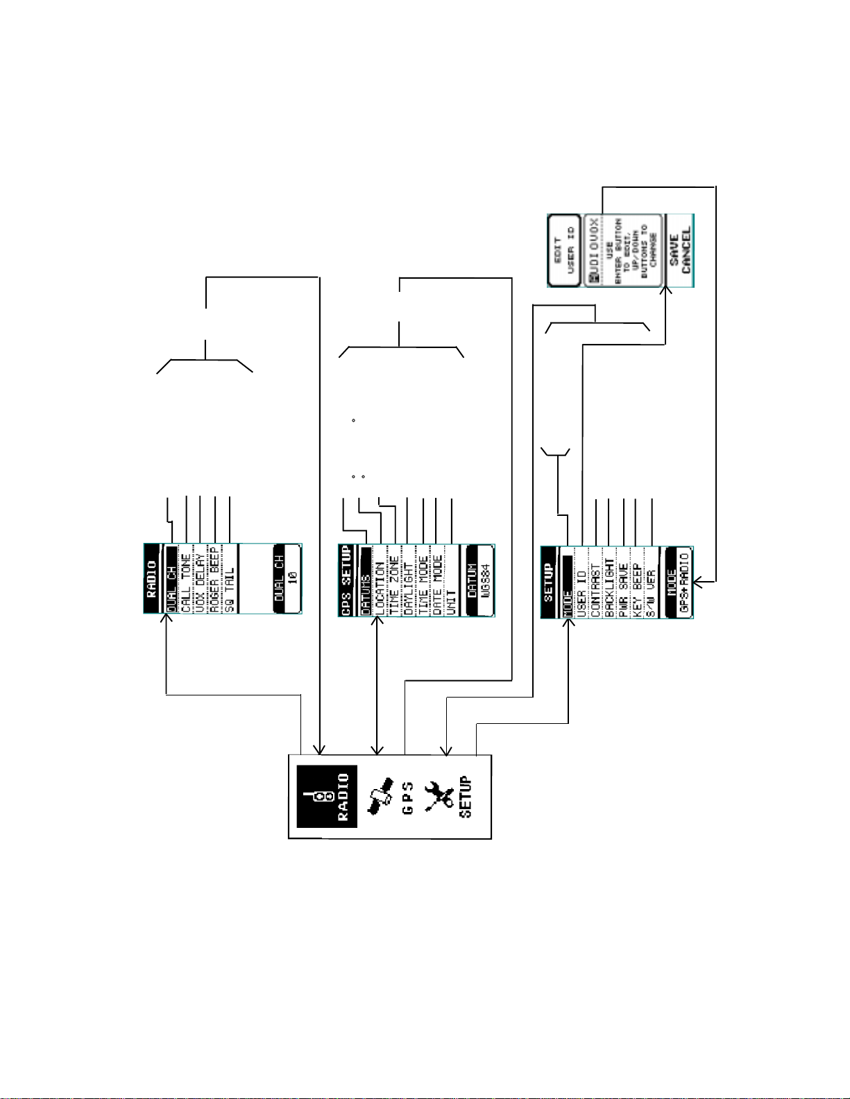
SETTING UP THE GMR-GPS UNIT
After the GMR-GPS unit is turned on, it should be set up and/or tailored for operation
according to user specific needs. To accomplish this, the basic SETUP mode must be accessed
and the required information needs to be entered. Access the SETUP mode as follows:
1. From either of the GPS Standb y modes , press the PAGE button five times ( from the radio
only mode press the P A GE button once); the unit should beep each time the button is pressed.
2. When the SETUP page appears, the display will show a highlighted (boxed) RADIOicon,
GPS icon or SETUP icon.
3. Use the Up/Down wheel key switch to highlight the SETUP icon; then momentarily press
the Enter switch (the spring-loaded center position of the wheel key); the SETUP menu will
appear on the display as shown below, and MODE will be highlighted.
4. To scroll through this menu, use the Up/Down positions of the wheel key. To change the
parameters of each menu item, proceed as follows:
a. MODE - Press Enter; a menu appears in the center of the display and, below the
MODE bar, at the bottom of the menu, will appear the current mode ( RDO (radio) ONL Y,
GPS ONLY or GPS + RADIO).
(1 ) Press the wheel key up or down to change the mode to the one you want (RDO
ONLY , GPS ONLY or GPS + RADIO).
(2 ) When the desired mode appears below the MODE bar , press Enter ; the popup menu
disappears from the screen and the selected mode remains displayed below the
MODE bar.
PRESS ENTER
TO SELECT
MENU ITEM
FOR CHANGE
PRESS
WHEEL KEY
UP OR DOWN
TO SELECT
MENU ITEMS
RADIO ONLY
GPS ONLY
GPS + RADIO
Basic Setup Menu Selections
b . USER ID. - Press the wheel key switch up or down to highlight the USER ID item; the
current USER ID appears in the window at the bottom of the display. Press Enter. The
EDIT USER ID page appears; The user identification code consists of eight characters ,
which can be all letters, all numbers or a combination of each. When the edit page
appears, the first character is highlighted by the cursor . Enter the desired user ID as
follows:
18
Page 19

(1 ) Press Enter; an alphanumeric window appears
with a highlighted number/letter corresponding
to the character presently being used.
(2 ) Using the Up/Down wheel key , highlight the first
ID character desired and press Enter. The first
character changes and the cursor moves to
the second character position.
(3 ) Repeat step (2) for the second desired character;
the cursor moves to the third character position.
(4 ) Repeat step (2) for the third through eighth
character , if used; then press Enter .
(5 ) Using the Up/Do wn wheel key, highlight SA VE at the bottom of the screen and press
Enter to save the user ID code just entered. The Setup page reappears.
c. CONTRAST - Press the wheel key switch up or down to highlight the CONTRAST item;
then press Enter. A popup menu appears with a contr ast lev el between 1 and 10 high
lighted; the level also appears in the status bar at the bottom of the display. Use the
Up/Down wheel key to select the desired display contr ast for the LCD. Set the contrast at
about halfway (4 or 5) for best display. Press Enter to confirm the selection.
d. BACKLIGHT - Press the wheel key switch up or down to highlight the B A CKLIGHT
item; then press Enter . A popup menu appears with the bac klight duration (or none)
highlighted; the selection also appears in the status bar at the bottom of the displa y.
Use the Up/Down position of the wheel key switch to select the LCD backlight feature
OFF, 15 SEC, 30 SEC, 1MIN or ST AY ON as indicated in the bottom status bar. Press
Enter to confirm the selection.
NOTE: Be mindful that use of the backlighting feature for longer periods of time will
deplete battery power more quickly .
e. PWR SAVE - Press the wheel key switch up or down to highlight the PWR SAVE item;
then press Enter. A popup menu appears with the current selection highlighted; the
selection also appears in the status bar at the bottom of the display. Use the Up/Down
position of the wheel key s witch to select the desired power sa ve option at OFF, SHOR T
(3 seconds) or LONG (5 seconds) as indicated in the bottom status bar. Press Enter to
confirm the selection.
f. KEY BEEP - Press the wheel key switch up or down to highlight the KEY BEEP item;
then press Enter. A popup menu appears with the current selection highlighted; the
selection also appears in the status bar at the bottom of the display. Use the Up/Down
position of the wheel key switch to turn the key beep ON or OFF as indicated in the bottom
status bar. Press the Enter button to confirm the selection.
g. S/W VERSION - This menu line, when highlighted, indicates the current SoftWare
version incorporated into the unit.
Adjusting the Volume:
This adjustment applies to the radio modes only.
1. With the unit in the RDO ONL Y or GPS + RADIO standb y mode (standby page displa yed), use
the Up/Down wheel key in the up or do wn position; a VOL bar graph display appears.
19
Page 20

2. Move the wheel ke y in the up or down position to increase or decrease the volume setting. The
volume bar graph will increase or decrease in steps , accordingly, to a maximum of 16 or a
minimum of 1.
SETTING UP THE GPS FEATURE
Now that the basic setup procedures have been performed, you must now perform the setup procedure for the GPS f eature . This is accomplished as fo llows:
1. From the SETUP displa y page , select the GPS mode using the Up/Down wheel k e y; the
GPS icon will be highlighted (box ed). Then press Enter .
2. The GPS menu shown below will appear . The items in this menu are accessed and edited in
the same manner as explained previously for the SETUP menu; use the Up/Down/Enter
wheel key switch as before.
a. DA TUMS - Since maps and charts are created using a starting reference point called a
datum, this starting point will differ from map-to-map. The most common mathemati
cal ellipsoid used is WGS-84 (World Geodetic System 1984). In addition to the WGS-84
standard, a great many other datums are available for entry depending on user location.
If you use maps or charts specifying a datum other than WGS-84, you should change
the datum applicable to that region to reduce position errors. If you are not sure of which
datum to apply , use the WGS-84 datum for best o verall perf ormance.
b. LOCA TION - The Location item pro vides you with f our choices f or displa y of positional
information; namely, Degrees (DDD°), Minutes (MM’), Seconds (SS”), Degrees and
Minutes only (DDD°MM.MM’), Degrees only (DDD.DDDDD°) or a UTM (Universal
Transverse Mercator). The capability to adjust the time offset v alue is av ailab le under
the OTHER option of the TIME ZONE function below .
c. TIME ZONE - Selecting the Time Zone provides y ou with a choice of
the available zones relative to the United States and its possessions.
These consist of A TLANTIC, EASTERN , CENTRAL, MOUNT AIN,
PACIFIC, ALASKA, HAWAII and SAMOA. In addition, Time Zone also
offers a choice of O THER, whereby the unit can be programmed f or
anyother specific area not listed. If O THER is selected, the parameters are entered under UTC (Universal Time Clock) Offset. This
provides you with the capability of adjusting the Time Offset value
between +12 and -12 in reference to Greenwich, England.
d. DA YLIGHT (Sa vingTime) - This menu item provides y ou with the
capability of choosing the daylight saving time mode (SAVE OFF/
SA VE ON). In either case, the time must be entered manually .
e. TIME MODE - Selecting the Time Mode item allows you to select the way the time is
presented on the display (either 12 HOURS or 24 HOURS clock format).
f. DATE MODE - Selecting the Date Mode item allows you to select the wa y the date is
presented on the display (DD-MM-YY, MM-DD-YY, or YY-MM-DD), where M=month,
D=day and Y=y ear .
g. UNIT - This item allows you to specify distance measurements in METRIC
(Meters/Kilometers), STATUTE (Feet/Miles) or NA UTICAL units.
20
Page 21

PAGING THROUGH GPS FUNCTIONS
INITIALIZING THE GLOBAL POSITIONING SYSTEM MODE
Before using the GPS mode of your GMR-GPS unit for the first time, the GPS receiver needs to
automatically determine its location. To initialize the GPS receiver, proceed as follows:
W A TCHING SA TELLITE A CQUISITION ON THE GPS ST ANDBY/STA TUS P A GES
Your GMR-GPS unit operates on positional data acquired from NA VST AR satellites . To introduce your
unit to this information:
1. Find a large, relatively open area that provides a clear vie w of the sky, with a minimum of
obstructions, such as buildings, radio towers, etc.
2. Press and hold the Power ( )/Mark (M) button on the left side of the unit for at least 2
seconds.
3. A beep and melody will sound and the standby screen will appear on the LCD. If the unit is
being turned on for the first time, the standby screen will default to the RADIO + GPS mode,
or it will reflect the standby screen for the mode previously used.
The GMR-GPS unit needs to receive at least three strong satellite signals to find your location. The
standby page graphically shows the unit acquiring satellites as the satellite icons around the globe
circumference become animated and darken. SEARCHING appears under the ID bar at the top of the
display. When you see NA VIGATION appear, y our GMR-GPS has f ound y our location and y ou are
ready to use all of its GPS capabilities.
4. If the unit is ready for NAVIGATION, each of the satellites providing
current GPS user location should be highlighted, and should equal or
exceed 3 as shown around the circumference of the globe icon (4 or more
is preferable). If the unit is SEARCHING,wait approximately 5 minutes
for the satellite(s) to find your position. The NA VIGATION indicationshould
appear. Thereafter , during subsequent GPS operation, acquisition time
should only take from 5 to 45 seconds. If satellite acquisition does not
occur within approximately 7 minutes, a message appears indicating the
signal has been lost and asking whether or not you wish to initialize the
unit again. If NO is your option, the unit will indicate SLEEP MODE on the
GPS + RADIO and GPS ONLY standby page. Press the PTT button to
re-enter the SEARCHING mode. If YES is your option, the unit will re-enter
the SEARCHING mode.
SELECTING P A GES
As described earlier, the information needed to operate your GMR-GPS is contained on six main
pages; namely, the Standby page, Na vigation page, Map page, P ointer page , GPS Menu page and
Setup page. To scroll through the pages, simply press the PAGE button. Depending upon the Mode
selected, as explained previously, there can be three different Standby pages . The following discussion describes the three types of standby pages, plus the other five pages.
ST ANDBY P A GES
There can be three different Standby pages, each dependent on the Mode selected using the Setup
page.
21
Page 22

GPS + Radio Standby Page
The GPS + RADIO Standby page automatically appears as the default page if the unit is being
turned on for the first time, or if it is selected as the operational mode using the SETUP page. In
addition to depicting satellite acquisition (SEARCHING/NAVIGATION), this page also displays the
following information:
1. A user identification (ID) code consisting of eight characters maximum. If no user ID
code appears, refer to basic setup mode.
2. The number of acquired satellites. (This could fluctuate depending on clear-sky conditions
or the relative position of the unit’ s GPS antenna as it is carried or transported.)
3. The volume level bar graph relative to radio (GMRS) operation. (See
Volume
.)
Adjusting the
4. The current time, either on a 12-hour or 24-hour basis (refer to SETUP mode).
5. The primary GMRS channel number.
6. The GMRS CTCSS sub-code associated with the primary channel number (if one was
previously selected).
SEARCHING --
/NAVIGATION
SATELLITE
ACQUISITION
STATUS
CTCSS
CODE
NUMBER
PRIMARY
CHANNEL
(CH) NUMBER
USER
IDENTIFICATION
(ID) CODE
16-STEP VOLUME
BAR GRAPH
(USE
UP/DOWN
WHEEL
KEY TO ADJUST)
CURRENT TIME
(12 OR 24
HOUR FORMAT)
GPS + Radio Standby Page
GPS Only Standby Page
The GPS ONLY Standby page can be selected from the SETUP page using the MODE function
as previously explained. In addition to depicting satellite acquisition (SEARCHING/NAVIGATION),
this page displays the following information:
1. A user identification (ID) code consisting of eight characters maximum. If no user ID
code appears, refer to basic setup mode.
2. The number of acquired satellites as discussed before.
3. The current date in the format selected from the GPS SETUP menu (DATE FORMA T); this
format can appear as DD-MM-YY, MM-DD-YY or YY-MM-DD .
4. The current time, either on a 12-hour or 24-hour basis (refer to SETUP mode).
22
Page 23

UP/DOWN
WHEEL KEY
GPS Only Standby P age
Radio Only Standby Page and V olume Function
Radio Only Standby Page
The RADIO ONLY Standby page (shown abov e) can be selected from the SETUP page using the
MODE function as previously explained. Unlike the other two modes which include the GPS
feature, this standby page depicts a radio only display with the following information:
1. A user identification (ID) code consisting of eight characters maximum. If no user ID
code appears, refer to basic setup mode.
2. The volume level bar graph relative to radio (GMRS) operation. (See
Volume
.)
Adjusting the
3. The primary GMRS channel number.
4. The GMRS CTCSS sub-code associated with the primary channel number (if one was
previously selected).
The Gateway Page
To simplify the transition between GPS-related page displays, a Gateway page is provided which
allows you to jump between main pages in the GPS modes (GPS + RADIO and GPS ONLY), rather
than have to scroll through unrelated pages to acquire a desired page. When operating in a GPS
mode, the Gateway page can be acquired from any display. To accomplish Gateway page
acquisition:
1. From any display in either GPS mode, press and hold the PAGE button for at least 2
seconds; the Gate way display will appear, offering any one of six page selections to go to .
2. The title at the top of the Gateway display will differ according to the mode display it was
accessed from; e.g., if the GPS MENU page was in use, a jump to the Gateway page will
result in the Menu page icon being highlighted, and the page title will change to MENU.
3. T o access any of the six GPS menu pages from the Gate way page, use the Up/Do wn wheel
key to highlight the desired page icon; then press Enter to access the page.
4. To return to the Gateway page, simply press and hold the PAGE button for at least 2
seconds.
NOTE: Remember that a momentary press of the P AGE b utton, whether from the Gatewa y
page or the current main page will access the next menu page as explained
previously in
Scrolling Through the Menu Pages.
23
Page 24

PRESS
PAGE
PRESS
PAGE
PRESS
PAGE
PRESS
PAGE
PRESS
PAGE
PRESS
PAGE
GATEWAY PAGE ICONS
(HIGHLIGHT WITH UP/
DOWN WHEEL KEY
AND PRESS ENTER TO
ACCESS DISPLAY
PAGES)
PRESS
PAGE
Gatewa y Page Relationships
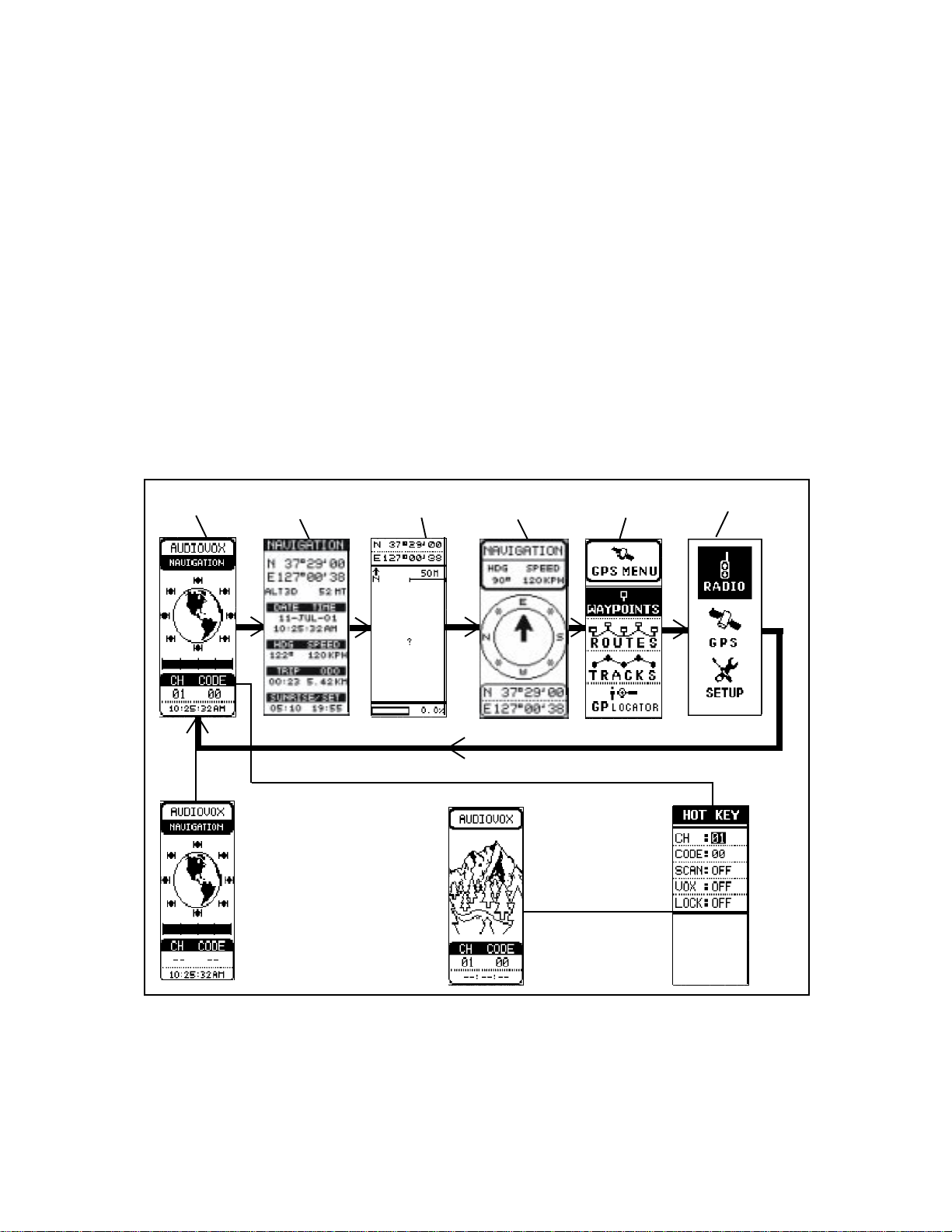
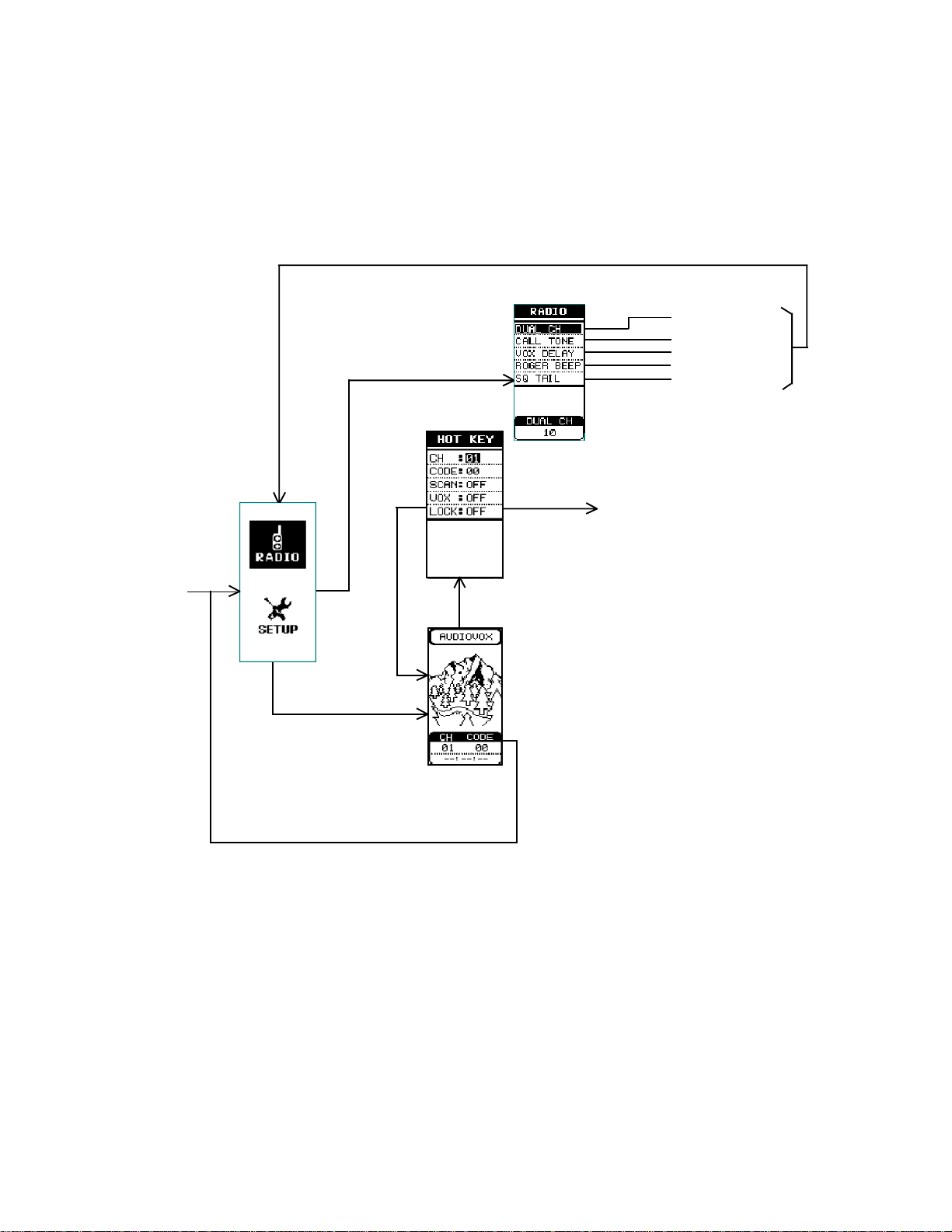
Hot Key Menu Access
A HOT KEY menu is accessible from either the GPS + RADIO or RADIO ONLY standby page; this
page appears when the Enter switch is pressed, and provides you with quick access to the basic
radio functions. Refer to the section on radio operation for a detailed explanation of these items.
PRESS ENTER
RADIO
ONLY
PRESS ENTER
GPS +
RADIO
24
Page 25

The NA VIGA TION Page
The NAVIGATION page presents a summary of the important parameters entered into, or computed by your GMR-GPS unit. This page can be accessed from the GPS + RADIO or GPS ONL Y
standby pages, or it can be accessed from the Gateway menu which is available from any of the
pages when operating in the one of the GPS modes. In addition, when the Enter button is
pressed, a ST ATUS page becomes available which shows the satellite number acquired by the
unit, and the relative strength of each of these signals. The par ameters shown on the
NA VIGATION page include:
1. Coordinates - The Latitude (N/S) and Longitude (E/W) of your present position are
displayed.
2. Altitude (AL T) - This line of the display indicates present altitude above sea lev el in
Metric (Meters) or Statute/Nautical (Feet) equivalents.
3. DA TE/TIME - The ne xt two lines present the current date and time-of-da y in the f ormat
entered into the SETUP menu.
4. HDG/SPEED - This line presents the current heading you are traveling on, and the speed
at which you are moving.
5. TRIP/ODO - This line presents the elapsed time of your current trip, and the distance
(odometer reading) you have traveled.
6. SUNRISE/SET - This line presents the time of sunrise and of sunset based upon the
information you have entered in the SETUP menu with respect to the time zone, time
format (12 or 24 hour) and daylight saving time.
NOTE: When the NA VIGATION page is displayed, the o v erall displa y contrast can be
adjusted using the Up/Down wheel key.
ADJUST CONTRAST
WITH UP/DOWN
WHEEL KEY
PRESS ENTER
The Navigation and Status Pages
25
Page 26

The Mark (Waypoint) P age
W aypoints are the coordinates of user-selected specific geographical or man-made objects along
the route you are taking to your destination or endpoint. Geographical objects could be a lake, pond,
hill, etc., while a man-made object could be a barn, house, electric tower, etc. Each of these
objects along your way can be marked and stored in your GPS unit so that your return path is
plainly marked and can be retraced easily . The MARK page appears whenev er the Mark (M) button is
momentarily pressed; this page presents the options of SA VEing the wa ypoint, transmitting (SEND)
the waypoint or accessing a MAP VIEW (on the map page) of the wa ypoint in question. If the send
option is used, your present location (coordinates) is transmitted to another GMR-GPS unit so it
knows where you are. The f ollowing display appears when the Mark (M) button is momentarily pressed:
WAYPOINT SYMBOL
WAYPOINT NAME
WAYPOINT
COORDINATES
The Mark Page
The page displays the following information:
1. Wa ypoint Symbols - There are 38 symbols representing common items and structures
that can be chosen to represent a waypoint on the Map and P ointer pages. These
symbols can be geographic or man-made objects.
2. Wa ypoint Name - Six alphanumeric characters are availab le to describe or represent a
waypoint; usually, just three characters are sufficient unless you wish to give the waypoint
a name (ID), followed by the number of the waypoint (001, 002, etc.).
3. Waypoint Coordinates:
a. Latitude - Latitude is a position resting North or South of the Equator. The user can
edit the displayed Latitude position.
b . Longitude - Longitude is a position resting East or West of the Prime Meridian. The
user can edit the displayed Longitude position.
NOTE: The displayed Latitude and Longitude represents the last kno wn position. This
positional information can be saved by pressing the Mark (M) button, using the
Up/Down wheel key switch to highlight the SAVE selection, and pressing Enter.
26
Page 27

4. SAVE - When SAVE is highlighted, the coordinates can be saved in memory. In addition,
the saved waypoint coordinates can be retrieved using the GPS MENU page and highlighting the WAYPOINTS field.
5. SEND - To transmit the current coordinates, together with user (your) ID, to a remote
user GMR-GPS unit tuned to the same channel (and CTCSS sub-code), simply highlight
the SEND field and press the Enter switch. At the receiving unit, a loud special tone will
be heard signifying receipt of the coordinate information. This inf ormation can also be
accessed from the GP LOCATOR field in the GPS MENU display.
NOTE: Wa ypoint names cannot be sent (transmitted) when the SEND function is used.
6. MAP VIEW - This option allows y ou to vie w the wa ypoint you just entered on the map
page. To do this, highlight MAP VIEW and press Enter; the map page will appear showing
the waypoint at the giv en coordinates with its symbol and w aypoint number. Press PAGE
to return to the MARK page.
The MAP Page
The map page presents a picture of where you are going. You, represented by the flashing square,
proceed toward your destination and leave a trail, or track log. As you travel, you can make use of
waypoints (specific geographic or man-made objects) that can mark your route as y ou trav el. These
waypoints also mak e it easy for y ou to retrace y our steps, estab lishing a route back to y our starting
point.
To better appreciate where you are and the direction you are headed in, the map page includes
several other useful features to guide your way:
1. A Compass indicator.
2. A map scale is displayed indicating the relative distance in user-selected units; just toggle the
Up/Down wheel key to adjust the map scale f or a con v enient displa y.
3. A status bar appears at the bottom of the display signifying the amount of memory used
between 0 and 100%.
4. Two information bars at the top of the display automatically scroll through the following
parameters, changing the data presentation about every 3 seconds:
a. Present Position (Longitude and Latitude)
b . Altitude
c. Current Date and Time
d. Heading (HDG)
e. Speed of travel
f. Ov erall Trip (TRIP) time
g. Odometer (ODO)
h. Bearing (BRG)
i. Distance (DST) traveled to target (waypoint or endpoint)
5. When the Enter switch is pressed, a sub-menu appears in the center of this screen, and
provides several options related to your trip; these options can be highlighted using the
Up/Down wheel key; then press Enter to change the highlighted data:
27
Page 28

CURRENT LONGITUDE
CURRENT LA TITUDE
AL TITUDE
CURRENT TIME
HEADING
TRAVEL SPEED
TRIP TIME
ODO (ODOMETER)
BEARING
DIST ANCE
TRUE NORTH
POINTER
PERCENT
MEMORY
USED BAR
MAP SCALE
PRESS ENTER
ANIMA TED
BOX SYMBOL
(YOU) OR
QUESTION
MARK (LOSS
OF TRACK)
MAP P AGE
SUB-MENU
The Map Page
a. AHEAD/NORTHWARD? - When this item is highlighted, press Enter to orient the top
of the map display with respect to waypoints or targets ahead of your intended track,
or with respect to True North.
b. A UTO/MANU AL ZOOM? - When this item is highlighted, press Enter to select the
display scale Automatic or Manual zoom function.
c. SYMBOLS ON/OFF? - When this item is highlighted, press Enter to turn the display
symbols ON or OFF.
d. SAVE TRIP? - When this item is highlighted, press Enter to store a particular trip in
the GPS TRACKS function.
e. NEW TRIP? - When this item is highlighted, press Enter to erase previous trip data.
NOTE: Two additional options -- STOP NA V? and SKIP WPT? -- appear on this sub-
menu during the trip. The SKIP WPT? function appears on the map displa y when
it is accessed from the ROUTES menu during the GPS GO ALONG mode
function. This enables you to skip a waypoint in the route; e.g., go directly from
waypoint C to E in the route, thereb y skipping waypoint D. ST OP NAV? will
terminate the trip along the chosen route, and is available during navigation
trackback and go to operation in the GPS waypoint, track and GP locator modes.
The POINTER Page
When you are moving, with no particular endpoint or target destination, the pointer page will show
you in which direction you are moving, and at what speed. If you are traveling to a specific
endpoint or destination, the pointer page will then show you the name of the location, the distance
to the location, and the time it will take to get there. The pointer page displays the f ollowing information:
1. A Compass Rose with large central directional arrow indicates the direction you are going
in.
28
Page 29

2. Whether or not the satellite information is sufficient for the unit to provide accurate positional
information (SEARCHING or NA VIGA TION). The indication provides the le vel of accuracy of
the position based upon the number of satellite signals being received.
3. An information bar at the bottom of the display permits viewing the following parameters
when the Up/Down wheel key is used:
a. LATITUDE - Degrees , minutes and seconds (dependent on setup selections).
b. LONGITUDE - Degrees, minutes and seconds (dependent on setup selections).
c. D A TE - The current date (dependent on setup selection)
d. TIME - Hours and minutes (dependent on setup selection).
e. ALTITUDE - :Your altitude above sea level in Meters or Feet.
f. HEADING - Current heading in degrees.
g. ODOMETER - The distance trav eled.
h. TRIP TIME - The elapsed time since your trip began.
i. SUNRISE - Time in hours and minutes of sunrise (dependent on setup selections).
j. SUNSET - Time in hours and minutes of sunset (dependent on setup selections).
k. MAX. SPEED - The maximum speed traveled since last trip reset in MPH.
l. AVG SPEED - The a v erage speed of tra v el during your trip in MPH.
m. SPEED - The current speed of tra v el during your trip in MPH.
LA TITUDE
LONGITUDE
DA TE
TIME
AL TITUDE
HEADING
ODOMETER
TRIP TIME
SUNRISE
SUNSET
MAX SPEED
AVG SPEED
SPEED
NUMBER
OF
SATELLITES
SEARCHING/NAVIGATION/
SLEEP MODE
COMPASS ROSE
AND POINTER
PRESS ENTER
The Pointer P age
29
Page 30

4. When the Enter switch is pressed, a sub-menu appears in the center of this screen, and
provides several options related to your trip; these options can be highlighted using the
Up/Down wheel key; then press Enter to change the highlighted data:
a. AHEAD/NORTHWARD? - When this item is highlighted, press Enter to orient the top
of the map display with respect to waypoints or targets ahead of your intended track,
or with respect to True North.
b. RESET TRIP? - When this item is highlighted, press Enter to clear an e xisting trip
function, such as average speed, maximum speed, odometer, trip time, etc. The
graphic representation of the trip remains, but all other counters are reset.
c. INITIALIZE? - If you have relocated more than 600 miles since last using the unit,
this option, when highlighted, allows you to initialize the unit so it can receive new
location and speed data.
NOTE: Two additional options -- STOP NA V? and SKIP WPT? -- appear on this
submenu during the trip as a result of Wa ypoint Marking, Trackback, GP Locator
and Go Along mode functions.
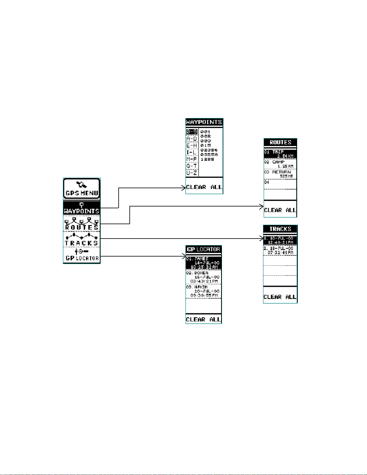
The GPS MENU Page
The GPS MENU page provides you with the means of navigating to your chosen destination. The
GPS menu page includes four selection fields; W A YPOINTS, ROUTES, TRA CKS and GP LOCA TOR.
The desired field is selected using the Up/Down wheel key.
WAYPOINTS
FIELD
ROUTES
FIELD
TRACKS
FIELD
GP LOCATOR
FIELD
GPS Menu Page
1. WAYPOINTS - W aypoints are specific geographical or man-made objects along the route
you are taking to your destination or endpoint. To retrieve a wa ypoint, toggle the Up/Down
wheel key switch to highlight the WAYPOINTS field; then press the Enter switch.
30
Page 31

a. The WAYPOINTS display presents an alphanumeric listing of the wa ypoints you ha ve
marked along your trip. In addition, they appear automatically in numeric order (unless
you enter a waypoint ID preceding the waypoint number) as they are marked and
entered sequentially. To access the waypoint column, press the Enter switch; the first
waypoint group (0-9) will be highlighted. Toggle the wheel key to select the category
corresponding to the first letter of the waypoint name (if the waypoint begins with a
letter); then press Enter . The first pre viously stored wa ypoint designation will be highlighted.
b . With the waypoint designation highlighted, press the Enter button to access the
WAYPOINT display; the wa ypoint name/number will be shown, together with its
symbol, location coordinates (Latitude and Longitude), and the option of GOing TO that
waypoint, DELETEing the waypoint or viewing the waypoint of the map display (MAP
VIEW). Any of these options can be accessed using the Up/Down wheel key; when
the desired option is highlighted, you can perform the following tasks:
(1) Change the Wa ypoint symbol.
(2 ) Edit the Waypoint name.
(3 ) Edit the Latitude and Longitude (position) of the Wa ypoint.
(4) GO TO the W aypoint position on the map page .
(5) DELETE the Wa ypoint.
(6) Access a MAP VIEW of the Waypoint.
WAYPOINT NUMBERS.
DESCRIPTIVE LET TERS
PRESS
ENTER
CAN ALSO BE USED;
E.G., WP01, WP02, ETC.
(IF W AYPOINT HAS AN
ID , THE ID PRECEDES
THE WA YPOINT
NUMBER)
c. Press the Enter switch to access and make all the required changes. To return to the
WAYPOINTS screen, press the PA GE b utton.
d. CLEAR ALL - This function will remove all stored w a ypoints from memory.
31
Page 32

HIGHLIGHT ITEM;
THEN PRESS
ENTER
PRESS PAGE TO
RETURN TO
WAYPOINT PAGE
Using and Editing the W aypoints During Your T rip
2. ROUTES - Routes consist of at least two or more waypoints that define a path to a
destination. This feature guides you from the first waypoint in the route to each
successive waypoint until you complete your trip. You can store up to 10 routes.
a. From the GPS MENU page , highlight the ROUTES field using the Up/Down wheel
key; then press Enter . The ROUTES display appears with route (01) highlighted. This
display depicts the name and travel distance of route 1; each route can contain up to
20 waypoints.
b . With route 01 highlighted, press Enter; the ROUTE display appears showing the name
of the route (TRIP) and the waypoints (A, B, C, etc.) making up the route. You
can now insert or delete a waypoint in the route by highlighting the desired field.
c. When the A waypoint is highlighted, press Enter; the INSERT/DELETE popup menu
appears. Use the Up/Down wheel key to select the desired action and press Enter; if
INSERT is chosen, the display reverts to the WAYPOINTS display which lists the
waypoints in that route. Use the Up/Down wheel key and Enter switch to select the
desired waypoint for inclusion in the route y ou are working on. The display will then
return to theROUTE display. If DELETE is selected, the w aypoint is deleted.
32
Page 33

HIGHLIGHT ITEM;
THEN PRESS ENTER.
PRESS P AGE T O
RETURN TO
ROUTES P AG E
Using and Editing the Routes on Your Trip
d. This process can be repeated until all the desired waypoints are incorporated into the
TRIP route (01) page.
e. Whenever a change is made to an item in the route , a MESSA GE displa y appears
when the PAGE button is pressed to return to the ROUTES display. The message
reminds you that you have made a change and if you want to save the route.
f. Press the PAGE button to return to the ROUTES field of the GPS MENU page or, if
you wish to edit a second route, press the Up/Down wheel key to highlight the next
(02) route; then press Enter to access the ROUTE page again.
g. When choosing the GO ALONG function after highlighting a route, the map page ap-
pears with the selected route displayed. If the Enter button is pressed, another menu
appears on the map page asking if you wish to ST OP NAV? or SKIP WPT? These
selections are explained in the
MAP Page
discussion on page 28.
3. TRACKS - As you trav el during your trip, using the wa ypoints as guideposts, you will lea ve
a trail or track. The track consists of waypoints that were generated automatically b y y our
unit as you traveled. This track can be used later when you return from your trip . Toggle the
Up/Down wheel key to highlight the TRA CKS field on the GPS MENU page and press
Enter. The TRACKS field can contain up to five individual tracks numbered 1 through 5. To
the right of the track number is the date and time at which the track w as generated. The
data points (waypoints) that make up the track are only generated when the unit is in
motion.
33
Page 34

HIGHLIGHT ITEM;
THEN PRESS
ENTER.
PRESS PAGE TO
RETURN TO
TRACKS PAGE
Using and Editing the Tracks on Your Trip
a. TRACKBA C K - With the TRACKS field of the GPS MENU highlighted, press Enter;
TheTRACKS menu appears with the first track position highlighted. Using the Up/
Down wheel key , highlight the desired track and press Enter . TRA CK LOG LO ADING
appears momentarily and the memory bar at the top of the screen indicates the
percent of track data points remaining to be loaded. When loading is complete , the
selected track is regenerated on the display, with the appropriate data points, and
TRACKBA CK is highlighted at the bottom of the display. This pictorial representation
of the track does not contain any data coordinates related to the MAP page.
b. TO BEGIN - With the track displa yed and TRA CKB ACK highlighted, it is possible to
view the beginning of the track on the map page. To do this, press Enter; a menu will
appear with TO BEGIN and T O END options. Use the wheel key to highlight
TO BEGIN and press Enter. This willcause the display to rev ert to the map page,
which will identify the beginning point of the track.
c. T O END - The T O END option is ex ecuted in the same manner as the T O BEGIN
option in step b; highlight the T O END option in the TRACKBA CK mode, and the map
page will identify the end point of the track.
d. Track Log Options - W arning displays appear whenev er the DELETE and CLEAR
ALL functions are to be executed with respect to the track log.
34
Page 35

4. GP LOCATOR - The GP LOCATOR field is used to display the coordinates
received from other GMR-GPS units or, when the Mark (M) button is pressed, your
coordinates are transmitted to another GMR-GPS unit to provide a fix on your location. To
access received coordinates, press the Up/Down wheel key to highlight the GP
LOCATOR field on the GPS MENU page; then press Enter . The GP LOCATOR menu will
appear and will list the ID names, date and time of the individuals who sent their position
data to you. This information can be extracted for vie wing purposes and/or viewed on the
map display, if desired.
Using the GP Locator Function
35
Page 36

TAKING A TRIAL RUN
Now that you are f amiliar with the GPS page f eatures and what functions they con ve y, it’s time to
take a short trip to test your navigation skills. You’ll need a relatively open area to perform this
exercise . Let’ s begin b y marking your current location; this can be considered a w aypoint, so it can
be used to guide you to your starting point on your return trip.
LET’S BEGIN
To begin with, let’s mark your current location as a wa ypoint.
NOTE: The GMR-GPS unit must be in the NA VIGATION mode (satellites acquired) before you
begin your trial run.
MARK YOUR WAYPOINT
Mark your current position as follows:
1. Make sure all desired parameters for your trip are arranged using the
SETUP menu.
2. Press the Mark (M) button; the MARK (W AYPOINT) page
appears. Since the GMR-GPS unit has now fixed your location, the
display will show a default mark of 001, followed by the coordinates
specifying your initial position.
3. Highlight the SA VE field and press Enter .
To make your trip more enjoyab le , let’s give your initial position a
more descriptive symbol and name before you commence your trip.
4. T o Change the Location Symbol:
a. With the MARK (WAYPOINT) page displayed, use the Up/Do wn
wheel key to highlight (box) the position symbol; then press
the Enter button.
b . The Symbols screen appears with the current symbol
highlighted.
c. Scroll through the symbols using the Up/Down wheel key
and select one that more closely describes your
location. Then press Enter . The MARK displa y reappears with
the new symbol adjacent to the location name.
d. Highlight the SA VE field and press Enter; the MARK
screen reappears.
36
Page 37

5. To Change the Location Name:
a. On the MARK screen, use the Up/Down wheel key switch
to highlight the waypoint name (001, 002, etc.) adjacent
to the symbol just changed; then press Enter. The alphanumeric
EDIT WA YPOINT NAME screen appears with the first
character of the location name highlighted.
c. Scroll through the alphanumeric listing using the Up/Down
wheel key, and create a name (no more than 6 characters),
such as HOME01 or HOTEL1, entering each
character (pressing Enter) as it is selected.
d. When the new name is complete, highlight SAVE and press
Enter. The MARK page appears and shows the
renamed initial waypoint next to the new symbol.
g. Highlight the SA VE field and press Enter; the MARK
screen reappears. Your new starting symbol and waypoint
name are now stored in GMR-GPS memory .
h. Press PAGE to return to the GPS MENU page.
6. To Change the W aypoint Location:
a. On the MARK screen, use the Up/Down wheel key switch
to highlight the Latitude and Longitude indication below the waypoint
name you just changed; then press Enter .
b . The EDIT LOCATION display appears with the North or South letter
highlighted.
c. T o change North to South and vice-versa, press Enter; a menu
appears with N or S highlighted (boxed). Use the Up/Down wheel key
to select the desired Latitude and press Enter. The first degree
position is highlighted.
d. T o change the deg rees, minutes and seconds information,
press the Up/Down wheel key in the down position to scroll from
left-to-right, or press the wheel key in the up position to scroll from
right-to-left, respectively. As each position is highlighted, press Enter
to select the value in question (a menu appears) as explained in step c.
e. After a value is changed, press Enter to address the next char acter,
then press Enter again to access the character for change.
f. Repeat this procedure to change the Latitude, then the Longitude,
if desired.
37
Page 38

g . T o sav e the changes, highlight SAVE and press Enter; the new
Latitude and Longitude specifying your location are stored
in memory; to cancel the changes, highlight CANCEL and press Enter .
LETS TAKE A SHOR T TRIP
Now that the unit knows where you are , press the PAGE button to access
the Map page, and let’s take a short trip.
1. Making sure the unit is ready to navigate (satellites acquired), walk at a
leisurely pace in astraight line for at least 30 to 50 feet, while observing
the Map page. Approximately 6 to 10 seconds are required for the
compass direction to stabilize.
2. Your immediate location is mimicked b y the box icon in the center
of the display; as you walk along, watch the icon proceed
along the track line, referred to as a track. This line
represents the path you have covered.
3. Now take a right turn. At this point, you can mark your position (press
the Mark (M) button), thereby entering another waypoint; if you wish,
give this location a suitable name as you’ve done before, and enter
the point into memory.
4. Walk in this new direction f or a few minutes and then stop. Again,
mark this destination or endpoint in the same manner as before.
Now that you hav e made this short trip, there are three w a ypoints marking
your track. Let’s retrace your steps back to the starting point using the
GO T O feature and the P ointer page.
GOING HOME
To travel back to your starting location:
1. Access the GPS MENU page and press Enter; the W AYPOINTS
screen appears.
2. On the WAYPOINTS screen, use the Up/Down wheel ke y switch
to highlight the first letter or number of the location name;
press Enter again to highlight the starting waypoint name to the
right. Press the PAGE b utton again to access the W AYPOINT page.
3. On the WAYPOINT page, GO TO is highlighted (boxed); press Enter .
4. The Map page appears showing the (box icon) and your ID symbol.
5. Adjust the map scale to enlarge the track; then press the PAGE
button to access the P ointer page.
6. TRACKING #1, the distance trav eled and the destination bearing,
appears at the top of the page, while the location (coordinates) appears
at the bottom. The compass pointer indicates the direction you must
travel to arrive at the starting point of your trip.
38
Page 39

LOCA TING ANOTHER GMR-GPS USER
During an excursion with another GMR-GPS user, it is possible to locate this user’s position
provided he/she transmits the position, thereby giving you the coordinates of the remote
GMRS-GPS unit. To transmit and receive the coordinates, both GMR-GPS units must set to same
radio channel number and CTCSS subcode number. By sa ving these coordinates, you will be able
to establish a route to this position using the pointer page compass. To use this feature, apply the
following example:
1. Allow the other user to travel a route to a destination of choice using the guidelines
established for the trial run outlined previously.
2. Along this route, the other user will enter a few waypoints, including his endpoint or
destination.
3. When the other user reaches the destination, the coordinates of this location must be
transmitted to your GMR-GPS unit in order for you to locate this position.
4. To transmit this information, the other user must select the waypoint, press the Mark (M)
button, highlight SEND and press Enter. The MARK SENDING display appears .
5 . The GP LOCATOR page appears on y our unit (receiving unit, accompanied by a unique
tone; the information displayed includes the remote unit coordinates
(Latitude and Longitude) and the remote user identification (ID)
name. In addition, the GO T O legend is highlighted (bo xed).
6. If the Satellite signal is lost prior to the location being sent, a
WARNING screen appears when the MARK button is pressed,
indicating loss of signal and suggesting the location be entered
and sent manually .
a. Highlight YES using the Up/Down wheel k ey, and press Enter;
the MARK page appears with the location information and the
option of SA VEing or SENDing (highlighted with a box) this data.
b . T o send the inf ormation, press Enter; to sav e the inf ormation,
SENDING
UNIT
RECEIVING
UNIT
highlight SA VE and press Enter . The data will be saved in
memory for transmission at a later time.
c. When NO is highlighted and Enter is pressed, the WAYPOINTS
sub-menu page appears with the waypoint in question highlighted.
7. On the receiving unit, if you press the Enter button, the map page will
appear, indicating the position of the other user relative to your position.
8 . Select the Pointer page using the PAGE button; the pointer will
show you the direction to the coordinates that were transmitted to
your unit.
9. Use the pointer page to establish a track to this position. The
compass pointer will eventually establish the direction you must go
to reach this location.
10. Walk in the direction of the compass pointer for at least 10 seconds;
the pointer page will not only show you the direction, but will also
indicate the distance and time to reach this destination.
11. When you are within approximately 10 seconds of your destination, a
message screen appears to advise you that you have arrived at your
destination point.
NOTE: The unit will not guide you to the exact spot, or coordinates
indicated, but it will be accurate to within 10 seconds of
Estimated Time of Arrival (ETA). Therefore, when you are within range of the
position indicated,start looking for the other party.
39
Page 40

GMR-GPS RADIO OPERA TION
In addition to its Global Positioning System (GPS) features, the GMR-GPS unit also provides
General Mobile Radio Service (GMRS) capability as a hand-held radio transceiver. As a GMRS
transceiver , the unit permits radio operation with features such as Coded Tone Controlled Squelch
System (CTCSS), V oice-Operated T r ansmission (VO X), Dual Channel Scan and Ke y Lock capability .
But the most unique feature is its capability, while operating in concert with the GPS function, of
transmitting user location (coordinates), with user identification (ID code), to another GMR-GPS unit
operating on the same frequency channel and sub-code with a single press of a button. The
transceiver is operational in the RADIO + GPS and RDO ONLY modes; make sure the GMRS
antenna is deployed for optimum radio operation.
RADIO CONTROLS
Power On/Off/Mark ( /M) Button (14)
Press and hold the power On/Off/Mark ( / M ) button
for at least 2 seconds. You will hear a confirming melody
to indicate the unit is on. To turn the unit off, press and
hold the button for at least 2 seconds.
Adjusting the V olume
With the unit powered on, and provided the GMR-GPS unit
is in the RDO ONLY or GPS + RADIO mode (standby page
displayed), toggle the Up/Downwheel key switch in the up position to increasevolume, or toggle
the wheel key s witch in the down position to decrease volume. The volume displa y will indicate the
current volume level by means of a bar graph.
The Enter function is executed when the wheel key is pressed; this function is used to access
menus , confirm entries and/or edit certain radio and GPS functions.
Monitor (MON) Button (15)
This button is used to to check activity on the current frequency before transmitting. Check activity
by pressing the Monitor (MON) Button longer than 2 seconds; you will hear static if the frequency
is clear.
to exit the monitor function. If audio is received, the icon will appear and reveal the strength of
the signal by virtue of the number of illuminated bars.
The monitor function will temporarily bypass the squelch setting and play all signals on a given
channel. This f eature is useful when communicating with other parties at extreme range.
Do not transmit if you hear conver sation.
Momentarily press the Monitor Button again
TRANSCEIVER
ANTENNA
DEPLO YMENT
Push To Talk (PTT) Button (1)
Pressing and holding this button will allow you to speak to any transceiver that is set to the same
channel and privacy code setting as yours. Hold the transceiver approximately 1 to 2 inches from
your face as you speak into the built in microphone . After you have finished speaking, release the
PTT Button to allow reception of incoming signals. It is not possible to transmit and receive at the
same time. The TX icon alongside the LCD Panel (13) will be highlighted while the PTT button is
pressed.
40
Page 41

Releasing the button allows the unit to rev ert to GMRS standby mode. When receiving an incoming
signal, the Monitor icon will be highlighted and depict the relative strenth of the signal.
The PTT Button can also be used as a two-way call ringer. Pressing the button twice quickly will
call another party on the same channel. The TX icon will be highlighted for approximately 3 seconds
and then go out.
External Speaker (SPK)/Microphone (MIC) Jack (5)
This jack accepts an optional Audiovox headset/microphone connector (Part No. FRS-BHST) to
provide hands-free GMRS operation.
ACCESSING THE RADIO SETUP FUNCTIONS
Prior to using the radio feature of your GMR-GPS unit, the operating parameters must be set up to
establish basic operating modes, such as channel scan, VOX operation, Roger Beep tone on/off,
and call melody selection. T o estab lish these parameters , proceed as follo ws:
1. Access the SETUP display and, using the Up/Down wheel k e y,
highlight RADIO; then press Enter . The f ollowing screen appears
with DUAL CH highlighted; DU AL CH is also highlighted in the
function bar below the menu.
2. Press the Enter button; a menu appears in the lower center
of the display with 01 highlighted. Press the Up/Down wheel key
to highlight one of 15 (01-15) secondary or dual radio channels
desired; then press Enter to select.
3. Using the Up/Down wheel key, select the CALL MELOD Y desired
(OFF or 01-09). When the menu appears , the current call melody
number (or OFF) is highlighted and the melody plays a short excerpt.
As you scroll through each melody number , the melody pla ys an
excerpt for approval. Highlight the desired number (or OFF) and press
Enter.
4. Using the Up/Down wheel key , highlight the VOX DELAY item and
press Enter for selection of the V OX DELAY function (OFF, 1-4 SEC).
5. Using the Up/Down wheel key, highlight the ROGER BEEP item and
press Enter for selection of the ROGER BEEP tone ON or OFF.
6. Using the Up/Down wheel key, highlight the SQ T AIL (Squelch Tail) item
and press Enter for selection of the Squelch Tail ON or OFF.
PRESS
ENTER
NOTE: Whenever y ou transmit, the receiving party (on the same channel) will hear the
short buzz, referred to as the “Squelch T ail”, when y ou finish the transmission. The
unit can be set to suppress (quiet) this noise by using the SQ T AIL ON option.
41
Page 42

EXPLANATION AND USE OF RADIO SETUP FUNCTIONS
The radio setup functions, as noted earlier, provide ancillary features, such as Roger Beep, Call Tone,
etc.
Dual Channel Selection
In the RADIO setup menu, the first item listed is DUAL CH.
- Highlight this line using the Up/Down wheel key and press Enter .
- A menu appears, listing 10 channels (01-10).
- Highlight the desired channel using the Up/Down wheel key, and press Enter.
When the radio is placed in the dual SCAN mode, this channel will be alternately scanned together
with the priority channel selected from the HOT KEY menu.
Call T one Selection Mode
The transceiver provides 9 user-selectab le call tone melodies (or OFF) to alert you to an incoming
call. T o select y our favorite call ringer melody:
- From the RADIO setup mode, use the Up/Do wn wheel key to highlight the desired CALL TONE
number; then press Enter . CALL T ONE appears highlighted at the bottom of the display with
the selection displayed.
-Press the Up or Down wheel key switch to select ringer melodies 1-9; at each ringer
selection, the call melody plays. The OFF selection is also availab le. Select the desired melody
and press Enter.
-The CALL TONE melody has no w been selected.
VO X Delay Setting
The V O X delay setting is accessed from the RADIO setup mode using the Up/Down wheel ke y; then
press Enter. Set the dela y f or 1-4 SEConds (or OFF) .
The V O X delay time selection setting pro vides a transmission delay after y ou hav e finished speaking. You may need to try different V O X time settings to determine the best value to suit your speaking habits. A longer delay setting will decrease the likelihood of the transmission ending during a
pause in your speech.
Roger Beep T one
The Roger Beep is a tone which is automatically transmitted whenever the PTT button is released.
This tone alerts the receiving party that the transmission has been terminated intentionally .
T o enable and disab le the Roger Beep tone:
- From the RADIO setup mode, use the Up/Down wheel ke y to highlight ROGER BEEP; ROGER
BEEP appears highlighted at the bottom of the display; then press Enter. ON or OFF is
displayed in a menu.
- Press the Up or Down wheel key to select ON or OFF as desired; then press Enter.
- The Roger Beep tone has now been selected On or Off.
Squelch T ail Setting
The squelch tail can be set ON or OFF as desired in the same manner as the Roger Beep tone. Refer
to the Squelch Tail NOTE on the pre vious page.
42
Page 43

Accessing the Hot Key Radio Operating Modes
Once the basic radio parameters have be set up, the GMRS functions can be activated as desired
during radio operation; these functions include selection of the primary operating channel (1-15) and
CTCSS sub-code (1-38), priority channel scan mode activation, V O X mode activation, and ke y lock
activation. These functions are present on the HOT KEY menu and are accessed as follows:
1. From GPS + RADIO or RADIO ONLY standby mode, press the
Enter switch to access the HO T KEY screen; the CH number will be
highlighted.
2. Press the Enter switch; a men u appears in the low er center of the displa y.
3. Select the desired channel with the Up/Down wheel key and press
Enter; then press Enter again.
4. Press the Up/Down wheel key switch in the down direction to highlight
CODE; then press Enter. A menu appears with a choice of CTCSS
subcodes.
5. Select the desired CTCSS sub-code (00-38) with the Up/Down wheel
key; then press Enter . Press Enter again.
6. Using the Up/Down wheel key, highlight the channel scan mode and press Enter to
activate the select scan OFF, SEEK or DU AL as desired. If SEEK is selected, the scan
icon ( ) appears on the standby page, and the radio will scan upwards through 15
channels; when a strong signal is receiv ed, scan will stop at that channel. If DUAL is
selected, the priority scan icon ( ) will appear on the standby page, and the radio will
scan between the priority channel (selected from HOT KEY menu) and the DUAL CH
selected from the SETUP menu.
7. Using the Up/Down wheel key, highlight and activate the VOX mode OFF, HIGH, MID or
LOW as desired. The VOX icon ( ) appears on the standby page.
8. Using the Up/Down wheel key, highlight and activate the K ey LOCK mode ON or OFF as
desired. The key lock icon ( ) appears on the standby page.
NO T E : When the K e y Lock mode is activ e, the Up/Do wn/Enter wheel
key becomes inactive; the PAGE button, MON button
and PTT button are not affected.However , if the Mark (M)
button is pressed, or the Up/Down wheel key is toggled,
the following W ARNING page appears , asking DO YOU
WANT TO UNLOCK? the Key Loc k function. Highlight
the appropriate field and press the Enter switch to affirm
the YES or NO selection. If YES, the K e y Lock mode is
turned OFF; if NO, the K ey Loc k mode remains active .
43
Page 44

EXPLANATION OF HOT KEY MENU USE
The HOT KEY menu provides an easy and f ast method of accessing and enabling the primary radio
functions when operating in the GPS + RADIO and RADIO ONLY modes.
Priority Channel Selection
In order to communicate with other GMRS units, both transmitting and receiving party must be on
the same frequency .
The radio function of the GMR-GPS has 15 channels (frequencies 1-15) as indicated on the HOT
Key page to the right of the CH item, and also on the standby page . Channels 1 through 7 are the
same frequency as FRS channels 1 through 7. Communication with Audiovox FRS and compatible
units is possible on these seven channels. Before transmitting on the selected channel, press the
MON button to check the activity on that channel. If there is activity on the selected channel,
change to another channel that is clear.
Change the channel as indicated in steps 1 through 3 on the previous page. The primary channel
number will appear on the Standby page.
CTCSS Mode (Sub-Channel) Selection
Coded Tone Controlled Squelch System (CTCSS) with 38 Sub-F requencies. This f eature allows you
to utilize the coded squelch tones (01–38) within a main channel. You can then communicate with
another party on the same main channel using the same subcode. (This filters out unwanted
transmissions without the same coded squelch tone). One of 38 different CTCSS subcodes may
be selected for each of the 15 channels.
T o change the CTCSS Sub-channel:
- From GPS + RADIO or RADIO ONLY standby mode, press the Enter switch to access the
HOT KEY screen; the channel number to the right of the CODE item will be highlighted.
- Press the Up/Down wheel key in the down direction to highlight the subcode to the right of
the CODE item; then press Enter . A menu appears with the current subcode
highlighted, if one has been entered previously (or 00)
- Then press the Up/Down wheel key switch to select the desired subcode for use.
- Press Enter to confirm the subcode in memory. The subcode will appear on the standby
Page with the main channel frequency number .
IMPORT ANT: To communicate with other GMRS units, they must be switched to the same
channel and CTCSS subcode. To communicate with other GMRS units that do not
have subcodes, switch your unit to the same channel with the subcode set to 00.
The CTCSS subcodes do not prevent others from hearing your transmission. This
will only allow you to ignore all traffic on a given channel not using the same subcode.
All Channel Scan Operation
This feature allows you to monitor all channels automatically f or valid signals. While scanning, you
can transmit and receive. When a signal is receiv ed, the scan is interrupted and will return to scan
mode 5 seconds after reception is terminated.
44
Page 45

T o enab le the channel scan mode:
- From GPS + RADIO or RADIO ONLY standby mode, press Enter to access the HOT KEY
display; use the Up/Down wheel key switch to highlight the scan mode to the right of the
SCAN item. Press Enter .
- OFF, SEEK or DUAL appears in a popup menu; use the Up/Down wheel key and
press Enter to choose the SEEK scan mode from its current condition. When SCAN
is in the SEEK mode, the scan icon ( ) appears on the standby page.
- When the unit doesn’t find any signals and you want to transmit, press the PTT switch to
return to home channel. The transceiv er will automatically resume scanning approximately 5
seconds after the communication is completed.
- If there is no activity and you want to leave the scan mode, highlight the SCAN item and
choose OFF; then press Enter to deactivate channel scan.
Dual Channel Scan Operation
This feature allows you to monitor two channels at the same time. The unit will continuously
monitor both the primary and a user -selected (dual) secondary channel. Received signals will be
played for 5 seconds, then the unit will resume scanning the two channels. Pressing the PTT
button during a received transmission will set the unit to transmit on the same channel. Pressing
the PTT button when no signal is received will set the unit to transmit on the primary channel. T o
activate the dual channel scan mode:
- From GPS + RADIO or RADIO ONLY standby mode, press Enter to access the HOT KEY
menu; use the Up/Do wn wheel ke y switch to highlight the SCAN item; then press Enter.
- OFF, SEEK or DUAL appears in a menu; use the Up/Down wheel key to choose DU AL
and press Enter to change the scan mode from its current condition. The dual scan icon
( ) appears on the standby display.
- The radio will begin scanning the user-selected secondary channel (selected in the SETUP
menu) and the current main channel selection.
- If there is no activity and you want to leave the dual channel scan mode, highlight the SCAN
item, choose OFF and press Enter to deactivate dual channel scan mode.
VO X Selection Mode
This option enables you to have hands-free conversation. When using the inter nal microphone/
speaker or an external microphone/headset (purchased separately), your voice or signal is
detected and the radio transmits and receives automatically. There is no need to press the PTT
button. T o set r adio for V O X operation:
- From GPS + RADIO or RADIO ONLY standby mode, press Enter to access the HOT KEY
menu; use the Up/Do wn wheel key s witch to highlight the VOX item. Press Enter .
- A menu appears with V O X choices OFF, HIGH, MID and LO W; press Enter to change
the V O X mode from its current condition. The V O X icon ( ) appears on the standby display.
NOTE: 1. A V O X LOW setting is the most sensitive and HIGH is the least sensitive. Select
LOW when in a quiet environment and HIGH f or a noisy environment.
2. The VO X DELAY (OFF, 1-4 SEC) will be set according to the selection made in
the VO X RADIO setup mode.
- T o deactiv ate the V O X mode, highlight the VOX item, choose OFF and press Enter.
45
Page 46

Battery Alert
When the charge indication bars on the battery icon ( ) begin to disappear on the LCD panel,
recharge unit or install fresh batteries. If the batteries are not replaced, the ( ) icon bars will fade
and a unique audio tone will sound each time a button or control is pressed; ho w ever, no display
changes will occur. This condition will warn the user that the batteries must be replaced, or that the
batteries must be recharged.
Batteries
There are three methods of powering the GMR-GPS:
1.Alkaline Batteries.
WARNING: Do not attempt to recharge Alkaline batteries.
2.Audiovox Rechargeable Ni-MH Batteries-(Rechargeable Ni-MH
batteries and Charging Stand not included). Us e only Audiovox
approved rechargeable batteries and charger when charging
batteries internal to the unit.
NOTE: To extend battery life, av oid overcharging the batteries.
3 .Various Brands of Rechargeable Batteries - Use of the Audiovo x charger with other brands
of rechargeable batteries is not recommended, as battery charging times will vary with differ
ent brands of batteries. Refer to the manuf acturer’s instructions f or charging other brands of
batteries.
NOTES FOR GOOD COMMUNICA TION
1 . The 15 channels of the GMR-GPS are shared on a ‘take turns’ basis. This means other g roups
may be talking on any of the channels. A common code of ethics/courtesy is to switch to
another vacant channel and not to attempt to talk over someone who is already using the
channel you first selected.
2. The GMR-GPS has been designed to maximize performance and improve transmission range
in the field. To av oid interference, it is recommended that you do not use the units closer than
5 feet apart.
3. For best transmission results, always keep your mouth about 2-3 inches from the microphone
(4) and speak slowly in a normal voice.
4. To increase battery life , av oid f eatures such as LCD backlighting f or prolonged periods of
time. Features such as this will reduce operating time considerably.
46
Page 47

Troubleshooting
MELBORPESUACELBABORPYDEMER
gnisserpelihwnoissimsnartoN
nottubTTP
deviecerlangisonrokaeWseirettabkaeWseirettabecalperroegnahC
detcelestimsnarttonlliwtinU
nottub)M(kraMnehwnoitacol
desserpsi
seirettabkaeWseirettabecalperroegrahC
reviecer
desserp
setilletasfossol
ytiralopyrettabtcerrocnIehtniseirettabehtllatsnI
tonedocycavirpdnalennahC
tegratsaemasehttes
wolootlevelemuloVgnisulevelemulovesaercnI
yltnetrevdaninottubTTP
ecnerefretnioidarevissecxE
lennahcralucitrapano
langisoidarfonoitcurtsbOraenronignitarepodiovA
degrahcsidylemertxeseirettaBseirettabecalperroegrahC
oteudtcerrocniatadnoitacoL
yrettabnodetacidnisnoitcerid
yart
otsgnittesoidarehttsujdA
ehtfosgnittesesohthctam
tinuSPG-RMGtegrat
hctiwsnwoD/pU
nottubTTPesaeleR
lennahctnereffidaotegnahC
-namrehtorosgnidliubegral
serutcurtsedam
nahtiwnoitacolotevoM
yksfoweivdetcurtsbonu
slangisdetnawnufonoitpeceR00tatesedocycavirpSSCTCretnednaunemOIDARotoG
ybraenrehtomorfecnerefretnI
llecsahcussecivedcinortcele
senilrewopcirtcelerosenohp
47
neewtebedocSSCTCderised
83dna10
evomrosecivedrehtoffonruT
gnirefretnimorfyawarehtraf
senillacirtcele
Page 48

Technical Specifications:
General
Frequency Range:
15 GMRS Channels 462.5500 - 462.7250 MHz
(7 Shared FRS)
Channel Spacing 12.5 KHz
Privacy Codes 38 for each main channel
Dimensions (W x H x D) 2.325 in x 5.25 in x 1.625 in
(Without Antenna) 59.1 mm x 133.35 mm x 41.3mm
Power Supply
Po wer Source Alkaline Batteries, AAA (4), 6 VDC
Operating Time
(Transmit: Receiv e: Standby) 14 hours (5: 5: 90 ratio)
Receiver
Useable Sensitivity >-119 dBm
Maximum A udio Output Power > 0.3 W att maxim um (8 Ohm )
Modulation Distortion < 5% (1 kHz 70%)
Ni-MH rechargeable, AAA (4),
4.8VDC, 650 mAh
(Based on alkaline batteries)
Transmitter
RF Output Pow er 1.8 W att maximum (high power)
0.5 Watt maximum (low power)
Maximum Deviation +/- 2.5 kHz
48
Page 49

This transceiver complies with FCC regulations for use in the United
States of America. Use in other countries may be prohibited or
restricted by l ocal regulation. Please check with the local regulating
agency before using this device outside the United States of America.
Main Channel Frequencies:
Channel Freq. MHz
1 462.5625
2 462.5875
3 462.6125
4 462.6375
5 462.6625
6 462.6875
7 462.7125
8 462.5750
NOTE: Channels 1 through 7 are shared with FRS radios .
Channel Freq. MHz
9 462.6250
10 462.6750
11 462.5500
12 462.6000
13 462.6500
14 462.7000
15 462.7250
49
Page 50

Continuous Tone Coded Squelch System Tone
Frequencies (in Hz)
CTCSS Freq. Hz CTCSS Freq. Hz
1 67.0 20 131.8
2 71.9 21 136.5
3 74.4 22 141.3
4 77.0 23 146.2
5 79.7 24 151.4
6 82.5 25 156.7
7 85.4 26 162.2
8 88.5 27 167.9
9 91.5 28 173.8
10 94.8 29 179.9
11 97.4 30 186.2
12 100.0 31 192.8
13 103.5 32 203.5
14 107.2 33 210.7
15 110.9 34 218.1
16 114.8 35 225.7
17 118.8 36 233.6
18 123.0 37 241.8
19 127.3 38 250.3
* 00 = No Tone
50
Page 51

90 DAY LIMITED WARRANTY
Applies to Audiovox Family Radio and General Mobile Service Products.
AUDIOVOX CORPORATION (the Company) warrants to the original retail purchaser of
this product that should this product or any part thereof, under normal use and conditions,
be proven defective in material or workmanship within 90 days from the date of original
purchase, such defect(s) will be repaired or replaced with new or reconditioned product (at
the Company's option) without charge for parts and repair labor.
To obtain repair or replacement within the terms of this Warranty, the product is to be
delivered with proof of warranty coverage (e.g. dated bill of sale), specification of defect(s),
transportation prepaid, to the warranty center at the address shown below.
The Company disclaims liability for communications range of this product.
This Warranty does not apply to any product or part thereof which, in the opinion of the
Company, has suffered or been damaged through alteration, improper installation,
mishandling, misuse, neglect, accident, or by removal or defacement of the factory serial
number/bar code label(s). THE EXTENT OF THE COMPANY'S LIABILITY UNDER THIS
WARRANTY IS LIMITED TO THE REPAIR OR REPLACEMENT PROVIDED ABOVE
AND, IN NO EVENT, SHALL THE COMPANY'S LIABILITY EXCEED THE PURCHASE
PRICE PAID BY PURCHASER FOR THE PRODUCT.
This Warranty is in lieu of all other express warranties or liabilities. ANY IMPLIED
WARRANTIES, INCLUDING ANY IMPLIED WARRANTY OF MERCHANTABILITY, SHALL
BE LIMITED TO THE DURATION OF THIS WRITTEN WARRANTY. ANY ACTION FOR
BREACH OF ANY WARRANTY HEREUNDER INCLUDING ANY IMPLIED WARRANTY
OF MERCHANTABILITY MUST BE BROUGHT WITHIN A PERIOD OF 30 MONTHS
FROM DATE OF ORIGINAL PURCHASE. IN NO CASE SHALL THE COMPANY BE
LIABLE FOR ANY CONSEQUENTIAL OR INCIDENTAL DAMAGES FOR BREACH OF
THIS OR ANY OTHER WARRANTY, EXPRESS OR IMPLIED, WHATSOEVER. No
person or representative is authorized to assume for the Company any liability other than
expressed herein in connection with the sale of this product.
Some states do not allow limitations on how long an implied warranty lasts or the exclusion
or limitation of incidental or consequential damage so the above limitations or exclusions
may not apply to you. This Warranty gives you specific legal rights and you may also have
other rights which vary from state to state.
Audiovox Electronics Corp., 150 Marcus Blvd., Hauppauge, New York 11788
1-800-290-6650
51
128-5385A
Page 52

© 2001 Audiovox Electronics Corp., Hauppauge, NY 11788 Printed in Korea
52
128-6146
 Loading...