

Page 1
Model FR-314
Two Way Family Radio
ÿ
яюэьы ыщ
Owner’s
Manual
Customer Service
1-800-645-4994
Page 2

CONGRATULATIONS ON YOUR SELECTION
OF THE FR-314 (FAMILY RADIO)
It is one of the most sophisticated and reliable two way
radios available.
BEFORE OPERATING YOUR FR-314 (FAMILY RADIO)
READ THIS MANUAL CAREFULLY
FCC WARNING
Replacement or substitution of transistors, diodes or other parts
of a unique nature, with parts other than those recommended
by the manufacturer, may cause a violation of the technical regulations of Part 15 of FCC Rules.
Page 3

FEATURES
Selectable Transmission Power Output Level
Electroluminescent Illuminated Display
Received Signal Strength Indicator
38 Privacy Codes
14 Channels
Remote Monitor Mode
Internal Voice Activation Circuitry
7 Call Tones
Adjustable Squelch
PERFORMANCE
Your transceiver will achieve its maximum operating range when
communicating with other transciever(s) in a flat open area with
no trees or buildings obstructing its signal. Range may be up to
two miles under such conditions. Obstacles such as buildings,
trees or mountains will tend to reduce the transceiver’s effective
range.
Page 4
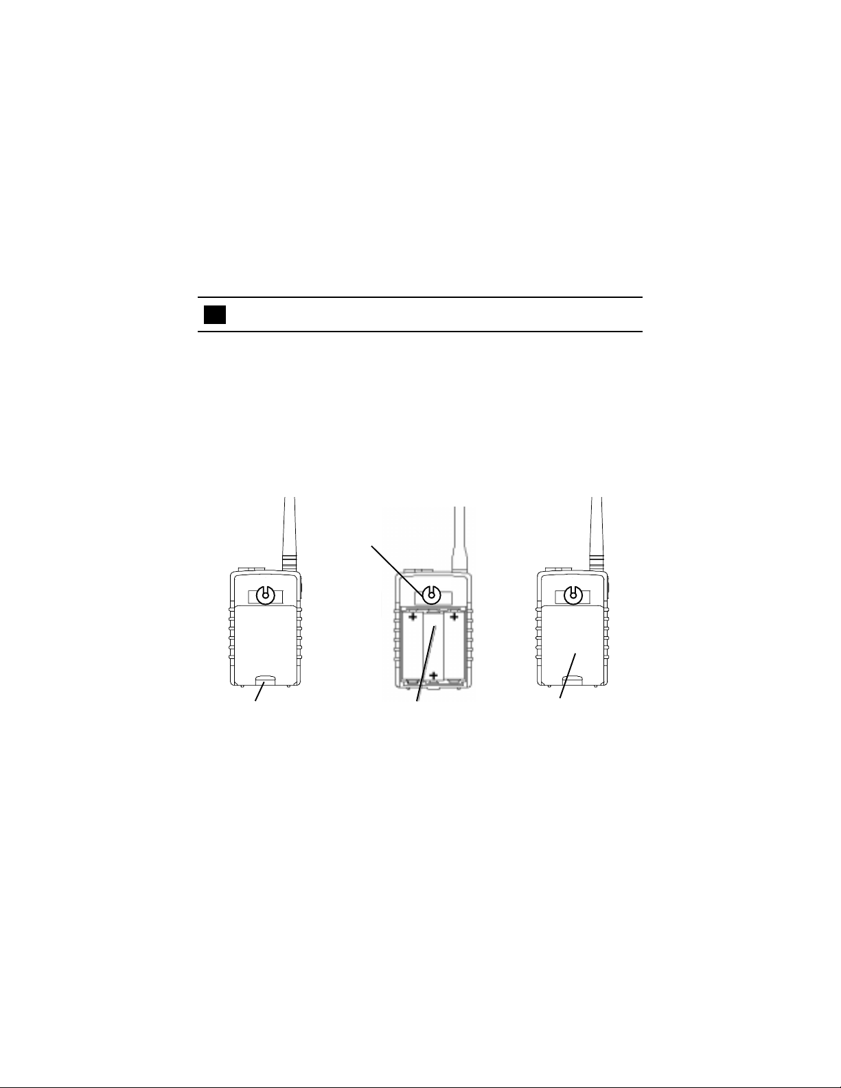
BATTERY INSTALLATION
Your FR-314 may be powered by the BAT-314 rechargeable battery pack or three alkaline “AA” cells. Alkaline batteries will provide the best performance from your transceiver. Remove the
battery cover by rotating and removing the belt clip. Unsnap the
battery compartment clasp, and lift the battery cover from the
transceiver. Be careful not to lose the belt clip retainer. Observe
the polarity symbols inside the battery tray when installing the
battery pack or alkaline batteries. Remember to lock the battery
compartment clasp in place when finished.
Belt Clip Retainer
1 Release the battery
compartment clasp
2 Remove the battery
cover and insert batteries
3 Close battery cover
Page 5

THE FR-314’s CHARGING STAND
The FR-314 transceiver kit includes a high capacity nickel metal
hydride battery pack and charging stand. The charging stand is
designed for use only with the Audiovox BAT-314 battery pack. Never
attempt to charge other batteries with the charging stand.
The FR-314’s four step battery strength indicator will display the
current state of charge of the batteries or battery pack in the unit. 3
solid bars indicates a full charge, one or no bars indicates a low
charge.
To charge your BAT-314 battery pack, plug the AC adapter into a
household electrical outlet, and insert the DC output connector into
the receptacle at the base of the charging stand. Before placing the
transceiver into the charging stand, be sure it has been turned off.
Once the FR-314 is placed in the charging stand, the charge rate
indicator on the charging stand will begin to flash, confirming the
charging process. The charge rate indicator will flash rapidly, when
the battery charge is low. As the BAT-314 battery pack charges, the
indicator will flash at a slower rate. A fully charged battery pack is
indicated by a flash rate of once every 15 seconds. When charging
a deeply discharged battery pack, several beep tones may be heard
during the first moments of charging.
Nickel metal hydride batteries do not have a “memory” so the BAT314 battery pack can be charged at any time, regardless of its current
state of charge
Page 6
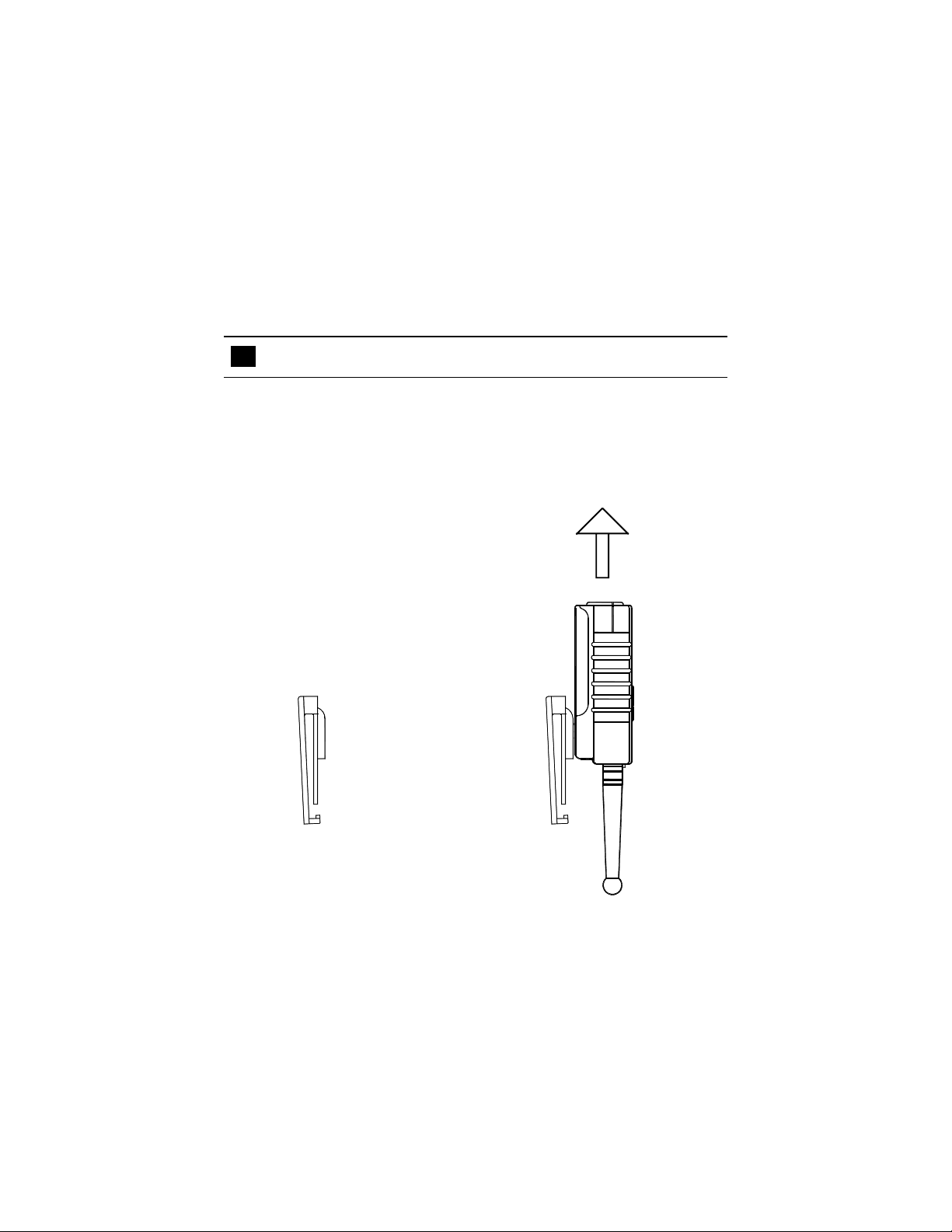
THE BELT CLIP
The FR-314 Family Radio Kit includes a quick release belt clip. This
can be used to secure the radio to a belt or pocket. The clip allows
quick access to the transceiver at all times. To use the belt clip,
attach it to a belt or shirt pocket, then slide the round hinge retainer
into the slot on the belt clip. A click sound will be
heard when the transceiver is locked in place.
The belt clip will hold the tranceiver securly,
while allowing it to rotate from side to side.
To release the tranceiver, rotate it 180
degrees and lift it straight upwards.
ÿþþ
Page 7

FUNCTION AND LOCATION OF THE CONTROLS
ÿþý
12
3
7
4
ÿ
5
6
8
9
10
ÿþþ
13
11
12
яюэьы ыщ
Page 8

1 Microphone jack
2 Speaker jack
3 Antenna
4 Call button
5 Up button
6 Down button
7 LCD display
8 Function button
9 Monitor / Illumination button
10 Power button
11 Speaker
12 Microphone
13 Push to Talk button
Page 9
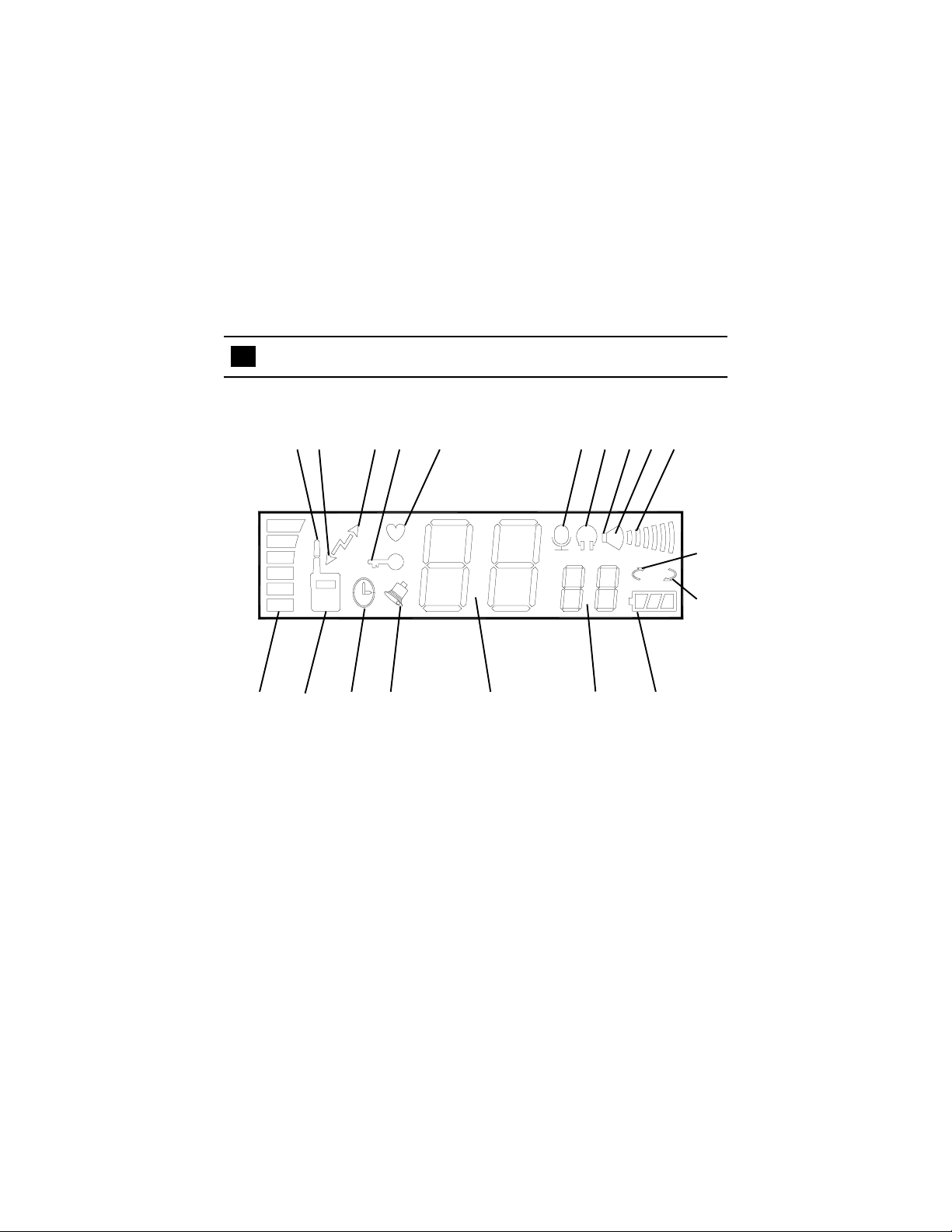
LCD DISPLAY
12 34 5 678910
ÿ
1 1 12 13 14 15 16 17
18
19
Page 10

1 High power transmission icon
2 Receive icon
3 Transmit icon
4 Keypad lock icon
5 Battery save icon
6 Voice activation icon
7 Monitor icon
8 Speaker icon
9 Beep tone indicator
10 Volume level graph
11 Signal Strength Indicator
12 Low Power Transmission Mode Indicator
13 Auto shut down timer icon
14 Call tone icon
15 Channel display
16 CTCSS privacy code display
17 Battery strength indicator
18 Scan up indicator
19 Scan down indicator
Page 11

USING YOUR FR-314
Turning the Transceiver On or Off
Pressing the red power button for 2 seconds will turn the FR-314 on
or off. If the button conformation tones are active, the transceiver
will play conformation tones when turned on or off.
Auto-shutdown Timer,
The FR-314 has an internal timer which can automatically shut the
transceiver off after 30 minutes of inactivity. To activate the autoshutdown timer, press the power button twice within 1 second, while
the transceiver is on. The clock icon will appear on the display,
whenever the auto-shutdown timer is active. If no buttons are pressed
and no signals are received for 30 minutes, the clock icon will flash
on the display, as indication that the auto-shutdown timer is about to
turn the transceiver off. The FR-314 will also sound warning tones
to alert its user that it is about to turn off. The auto shutdown warning
indicators will continue for 30 seconds. During this time, pressing
any of the buttons will reset the 30 minute timer. To disable, the
auto-shutdown timer, press the power button twice within 1 second,
while the transceiver is on.
ÿ
Auto Shut
Down Timer
Icon
Page 12

LCD Illumination
The FR-314 incorporates an electro-luminescent display. A
momentary press of the monitor button will illuminate the LCD. The
backlighting will remain lit for five seconds. If the up, down, call or
function buttons are pressed during this period, the LCD will remain
illuminated for another five seconds. This allows the backlighting to
remain lit while the operator makes adjustments to the FR-314.
Volume Adjustment
The volume of the internal speaker or headphones can be adjusted
with the up or down buttons. The current setting will be displayed by
the 6 bar indicator on LCD. If the button conformation tones have
been activated, the transceiver will beep each time a button is
pressed. A double beep tone indicates that the minimum or
maximum levels have been reached. When adjusting the volume
level, it is helpful to depress the monitor button, in this manner the
sound level can easily be adjusted to a comfortable level. It is
important to set the volume to a low level before attempting to use a
headset or external speaker because extremely loud sounds may
damage your ear.
Volume
Level Graph
ÿ
Page 13

Selecting the Channel
To adjust the channel, press the function button once or until the
channel number flashes on the display. Pressing the up or down
buttons momentarily, within five seconds, will change the current
channel number. The LCD will indicate the current setting and, if
the beep conformation tones are activated, the transceiver will sound
a conformation tone. When the highest or lowest channel is reached,
a double tone will be played as the channel setting wraps to the
opposite limit of adjustment. The channel number will stop flashing
and the FR-314 will return to standby if no buttons are pressed for 5
seconds, or if the call or PTT buttons are pressed.
Channel Display
ÿ
Page 14

Scanning Channels
The FR-314 can scan all 14 FRS channels to search for active
transmissions. To begin scanning, press the function button once
or until the channel number flashes on the display, then hold the up
or down button for 2 seconds while the channel number is flashing.
When the scan mode is activated, the scan icon will be displayed on
the LCD. A beep tone will also confirm activation of the scan mode
if the beep conformation tones are active. While in scan mode, the
transceiver will continuously check all channels for activity. If a signal
is received, the transceiver will play the entire signal and continue to
monitor its channel for one second. If no other signals are received,
the FR-314 will resume scanning. Pressing the function select or
PTT buttons will exit the scan mode.
ÿ
Scan Up
Indicator
Page 15

Transmitting a signal
To Transmit manually
1. Set the desired channel number.
2. Press and hold the PTT (Push-to-Talk) button while speaking slowly
and clearly in a normal voice, approximately 2 to 3 inches from
the microphone.
3. The transmission icon will be displayed while transmitting and
the signal’s strength will be displayed the indicator on the left.
4. Release the PTT button when you finish speaking to receive
incoming signals.
The Transmission icon will be displayed whenever the unit is
transmitting a signal, including the automatic transmissions of the
vox and monitor modes.
Continuous Transmission
When desired, the FR-314 can be locked into the transmit mode.
This is useful for continously monitoring all sounds in an area,
however battery life is dramatically reduced in this mode. To initiate
a continuous transmission, momentarily press the power button while
holding the PTT button together. The transmission indicator will
flash to whenever the FR-314 is in continuous transmit mode.
Momentarily pressing the PTT button will terminate the transmission.
Remember, no signals can be received while transmitting.
Transmission icon
Page 16

Transmission Power level
The FR-314 transceiver has two available transmit power levels.
The high power transmits signals at the regulated limit of 500 milliwatts. The low power level transmits at 200 milliwatts. When using
the FR-314 to communicate with other transceivers at close range,
it is possible to increase its battery life, by setting its transmission
power level to the low setting. Maximum range communication will
require the higher setting. To adjust the setting, simply press the up
or down button momentarily while transmitting. The FRS Radio icon
on the display will show a short antenna in low power mode and a
long antenna in high power mode.
Low
power
High
power
Battery Save Mode
The FR-314 will automatically switch to battery save mode
if no buttons are pressed and no signals are received for 6
seconds. While the battery save mode is active, the transceiver will remain ready to transmit or receive signals and the heart
icon will flash on the display. This mode dramatically increases the
life of the FR-314’s batteries. The battery save mode will not function when the squelch is bypassed or adjusted to the zero setting.
Page 17

Receiving Signals
To Receive
1. Turn the transceiver on.
2. Check the battery condition on the display. If the battery icon
is displayed, charge or replace the batteries.
3. Set the desired channel number.
4. Adjust the volume control to the desired listening volume
by pressing and holding the monitor button while using the up
and down buttons to adjust the sound level.
5. The receive icon will be displayed when the
transceiver detects an incoming transmission and its signal
strength will be displayed by the indicator on the left.
When communicating with other transceivers at extreme
range or when it is desirable to receive weak signals, the
monitor button may be used to bypass the squelch and listen
to all activity on a channel. Press and hold the monitor button
whenever this is desired.
Continuous Monitor Mode
The monitor feature may be locked on by pressing and holding the
monitor button, then pressing and holding the PTT button. Releasing
the monitor button, then PTT button will initiate the continuous monitor
mode. When in continuous monitor mode the receive icon will be
displayed and the signal strength indicator will display the strength
of any signals received. Pressing the monitor button momentarily
will return to the standard reception mode.
Page 18

Adjusting the Squelch
The FR-314 has 5 different squelch settings. These settings determine the strength that an incoming signal must have in order to be
played by the FR-314’s internal speaker or through a headset. The
higher the setting, the stronger the signal must be in order for the
FR-314 to play it. If you desire to communicate with other transceivers in close proximity, the squelch should be set high to eliminate
unwanted weak signals. If the transceiver is being used at extreme
range, the squelch should be set low to allow reception of weak
signals. Level 0 will bypass the squelch entirely. For standard use,
level 2 is recommended.
The procedure for adjusting the squelch begins with the FR-314
turned off. While pressing and holding the function button and the
up or down button, turn the unit on. The display will show “
the current squelch level will flash on the LCD. Use the up or down
buttons to adjust the level. The FR-314 will return to the standby
state if no buttons are pressed for 10 seconds, or if the call or PTT
buttons are pressed.
” and
ÿ
Page 19

Using the Continuous T one Coded Squelch System (CTCSS)
Privacy Codes
This feature allows you to ignore transmissions from other transceivers that are using the same channel. One of 38 privacy codes
may be selected. The same code must also be selected on those
transceivers which you desire to communicate with. When in use,
the transciever will play only strong signals from other FRS units set
to the same code number. Keep in mind, however, that this feature
does not prevent others from listening to your transmissions. To
activate or deactivate the CTCSS mode, press and hold the call
button for 2 seconds, this will toggle the mode on or off. Upon activation the current privacy code number will be displayed to the right
of the current channel number on the LCD and will flash for 5 seconds to allow its adjustment. If no CTCSS number is displayed this
indicates that the system is off.
To select a CTCSS code number, activate the system as described
above and use the up or down keys to adjust the code number. If
the CTCSS mode was already active, a momentary press of the
call button will cause the current CTCSS number to flash on the
LCD, allowing its adjustment. The FR-314 will return to its standby
state if no buttons are pressed for 5 seconds, or if the call or PTT
buttons are pressed. See the table at the end of this manual for the
CTCSS frequency assignments
Channel number (1-14)
ÿ
CTCSS
code
number
(1-38)
Page 20

Selecting a Call Tone
The FR-314 has seven built - in call tones. To select a call tone,
press the function button twice or until the LCD displays “ x” the
current call tone number will flash on the right of the display. Pressing
the up or down buttons will select between the seven available
signals. Each signal will be played by the speaker or headset as it is
selected. Once a signal is chosen, the FR-314 will return to standby
state if no buttons are pressed for 5 seconds, or if the call or PTT
buttons are pressed.
ÿ
Call
Tone
Number
Sending a Call Tone
To Transmit the chosen signal, simply press the call button while
holding the PTT button. The chosen call signal will be played by the
speaker or headset and transmitted on the current channel, the call
icon will display on the LCD whenever a call signal is sent.
ÿ
Call
Tone
Icon
Page 21

Voice Activation (VOX)
The FR-314 has internal circuitry which will allow it to operate hands
free. The voice activation circuitry will activate the transmitter as if
the PTT button were pressed whenever its microphone detects the
users voice. This feature is particularly useful when using an external
microphone. To activate the Vox mode, press the function button
three times or until the vox icon flashes on the LCD. The transceiver
will show the current status with the words “on or off”. Use the up or
down buttons to select the vox mode on or off. After adjustment, the
FR-314 will return to the standby state if no buttons are pressed for
5 seconds, or if the call or PTT buttons are pressed. If vox operation
has been selected the vox icon will display on the LCD.
Voice Activation Icon
ÿ
Page 22

Adjusting the Vox Trigger Level
Whenever the Vox mode is selected, it is necessary to adjust its
sensitivity setting. There are four available adjustment levels. When
using the vox feature in areas where there is a lot of background
noise, choose setting number 1. To avoid inadvertent transmissions
in quiet areas, choose setting number 4. To adjust the vox sensitivity
level, press the function button four times or until “SE LX” displays
on the LCD. The vox mode must be already activated, or the
transceiver will not display the adjustment screen. The level may be
adjusted by using the up or down buttons. The FR-314 will return to
the standby state if no buttons are pressed for 5 seconds, or if the
call or PTT buttons are pressed.
ÿ
Vox
Sensitivity
Level
Page 23

Using the Monitor feature
The FR-314 has a unique feature which allows a pair of units to
operate as a remote monitoring system. A single unit to be placed
in an area and transmit sounds from that area to a second FR-314
transceiver. The monitor feature allows the user of the second
transceiver to check the status of the radio link between the two
transceivers and periodically “listen in” on the remote transceiver.
This is particularly useful as a baby monitor.
To use a pair of FR-314 transceivers in the monitor mode,
they must both have the CTCSS mode activated and be set to the
same Channel and CTCSS code. For the remote transceiver, activate
and adjust the vox mode as described earlier. Then press the function
button 5 times or until the monitor icon flashes on the LCD. The
transceiver will show the current status with the words “on or off”.
Use the up or down buttons to change the setting. After adjustment,
the FR-314 will return to the standby state if no buttons are pressed
for 5 seconds, or if the call or PTT buttons are pressed. If vox
operation has been selected the vox icon will display on the LCD.
Remember to reduce the volume setting of the remote transceiver,
if it is to be used as a baby monitor. If the transceiver will be used to
monitor an area for longer than 30 minutes, make sure that the shutoff timer is not active. Place the remote transceiver on its base with the
front, facing the area to be monitored.
ÿ
Monitor Icon
Page 24

Using the Monitor feature Continued
It is now possible for an FR-314 to receive sounds transmitted by
the remote FR-314 in monitor mode at any time. Pressing and holding
the PTT button, then momentarily pressing and releasing the monitor
button on the second FR-314 will initiate an 8 second transmission
from the remote transceiver. The monitor icon will flash to confirm
that a “listen in” request was sent to the remote receiver. The
following 8 second transmission can be used to check the radio link
between the two transceivers by observing the
received signal strength indicator on the left of the display.
This allows a user to move from location to location and have
confidence that he or she is within range of the remote
transmitter.
To “listen in” Press
and hold the PTT
button,....
яюэьы ыщ
Momentarily ,
press and
ÿ
release the
Monitor
button.
Page 25

Button Conformation Tones
The transceiver can be set to confirm each press of the function,
call, up or down buttons with a beep tone or, if the user prefers,
these confirmation tones can be turned off. Whenever the tones are
on, the letter B inside the speaker icon will be shown on the display.
To turn the beep tones on or off, press the function button five times
or until the speaker icon flashes on the LCD. The transceiver will
show the current status with the words “on or off”. Use the up or
down buttons to change the setting. The FR-314 will return to the
standby state if no buttons are pressed for 5 seconds, or if the call or
PTT buttons are pressed.
Beep Tone
Indicator
ÿ
Page 26

Keypad Lock
To prevent the transceiver’s settings from being inadvertently
changed, the keypad can be locked. When the keypad is locked,
only the volume is adjustable, the other functions can be viewed,
but not changed. This is useful when the FR-314 is being used
by small children, or when the unit is kept in a pocket. A key
icon will be shown on the display whenever the keypad is
locked. To lock or unlock the keypad, press and hold the function button for 2 seconds.
Keypad Lock Icon
ÿ
ÿ
Page 27

WARNING
Remove the batteries from the transceiver if it is not expected to
be used for long periods of time. This will eliminate the possibility of
battery acid leaking from the batteries and corroding the transceiver.
Avoid exposing the unit to water or extremes of temperature.
Do not use this device in or near a mining facility, which uses
remotely triggered explosives or in areas labeled “Blasting Area”.
Premature or accidental detonation may result.
Do not attempt to modify or in any way increase the output of this
transceiver. Its output is designed to meet the legal limits set by
the FCC.
Do not use this device or change its batteries in potentially explosive
atmospheres as sparks in such areas could result in an explosion.
Turn your transceiver off wherever posted notices restrict the use
of radios or cellular telephones. Facilities such as hospitals may
use equipment that is sensitive to RF energy.
Turn your transceiver off on board aircraft when requested to do so.
Do not place your transceiver in front of a vehicle’s air-bag. If the
air-bag deploys, it could propel the transceiver like a projectile.
This transceiver complies with F.C.C. Regulations for use in the
United States. Use in other countries may be prohibited or restricted
by local regulation. Please check with the local regulating agency
before using this device outside of the United States.
Page 28

SPECIFICATIONS*
General
Channels: 14
Frequency range: See Chart on p. 30
CTCSS codes: 38
Modulation Type FM 2.5 kHz
Operating Temperature Range: 14° - 140° F
Standby time (Alkaline): >60 Hours
Power Supply: 3 - 4.5 V DC
Receiver
Sensitivity at 12 dB Sinad: .25 Microvolts
Selectivity: 45 dB
Transmitter
High Power RF Output: 500 milliwatts
Low Power RF Output: 200 milliwatts
Maximum Deviation: 2.5 kHz
* These specifications are subject to change without notice.
They represent typical values, individual units may vary.
Page 29

Continuous Tone Coded Squelch System
Tone Frequencies
CTCSS Freq. Hz CTCSS Freq. Hz
1 67.0 20 131.8
2 71.9 21 136.5
3 74.4 22 141.3
4 77.0 23 146.2
5 79.7 24 151.4
6 82.5 25 156.7
7 85.4 26 162.2
8 88.5 27 167.9
9 91.5 28 173.8
10 94.8 29 179.9
11 97.4 30 186.2
12 100.0 31 192.8
13 103.5 32 203.5
14 107.2 33 210.7
15 110.9 34 218.1
16 114.8 35 225.7
17 118.8 36 233.6
18 123.0 37 241.8
19 127.3 38 250.3
Channel Frequencies
Channel MHz Channel MHz
1 462.5625 8 467.5625
2 462.5875 9 467.5875
3 462.6125 10 467.6125
4 462.6375 11 467.6375
5 462.6625 12 467.6625
6 462.6875 13 467.6875
7 462.7125 14 467.7125
Page 30

90 DAY LIMITED WARRANTY
Applies to Audiovox Family Radio Service Products.
AUDIOVOX CORPORATION (the Company) warrants to the original retail
purchaser of this product that should this product or any part thereof, under
normal use and conditions, be proven defective in material or workmanship
within 90 days from the date of original purchase, such defect(s) will be repaired
or replaced with new or reconditioned product (at the Company's option) without
charge for parts and repair labor.
To obtain repair or replacement within the terms of this Warranty, the product is
to be delivered with proof of warranty coverage (e.g. dated bill of sale),
specification of defect(s), transportation prepaid, to the warranty center at the
address shown below.
The Company disclaims liability for communications range of this product.
This Warranty does not apply to any product or part thereof which, in the opinion
ofthe Company, has suffered or been damaged through alteration, improper
installation, mishandling, misuse, neglect, accident, or by removal or defacement of the factory serial number/bar code label(s). THE EXTENT OF THE
COMPANY'S LIABILITY UNDERTHIS WARRANTY IS LIMITEDTO THE REPAIR
OR REPLACEMENT PROVIDED ABOVE AND, IN NO EVENT, SHALL THE
COMPANY'S LIABILITY EXCEED THE PURCHASE PRICE PAID BY PURCHASER FOR THE PRODUCT.
This Warranty is in lieu of all other express warranties or liabilities. ANY IMPLIED
WARRANTIES, INCLUDING ANYIMPLIED WARRANTY OF MERCHANTABILITY, SHALL BE LIMITED TO THE DURATIONOF THISWRITTEN WARRANTY.
ANY ACTION FOR BREACH OF ANY WARRANTY HEREUNDER INCLUDING
ANY IMPLIED WARRANTY OF MERCHANTABILITY MUST BE BROUGHT
WITHIN A PERIOD OF 30 MONTHS FROM DATE OF ORIGINAL PURCHASE.
IN NO CASE SHALL THE COMPANY BE LIABLE FOR ANY CONSEQUENTIAL
OR INCIDENTAL DAMAGES FOR BREACH OF THIS OR ANY OTHER WARRANTY, EXPRESS OR IMPLIED, WHATSOEVER. No person or representative
is authorized to assume for the Company any liability other than expressed herein in
connection with the sale of this product.
AUDIOVOX CORPORATION, 150 MARCUS BLVD., HAUPPAUGE, NEW YORK 11788
1-800-645-4994
128-5385
 Loading...