

Page 1
Model FR-214Model FR-214
Model FR-214
Model FR-214Model FR-214
OwnerOwner
Owner
OwnerOwner
Released 9-11-98.
Rev. A - Change Power station to charging stand pg. 3. 9-16-98
Rev. B - Change battery type from ni-cad to rechargeable pg. 3,4 9-16-98
Rev. C - Change W arranty and Customer Service telephone number 4-25-00
’s Man’s Man
’s Man
’s Man’s Man
ualual
ual
ualual
128-5379C
1 of 12
Page 2
Model FR-214
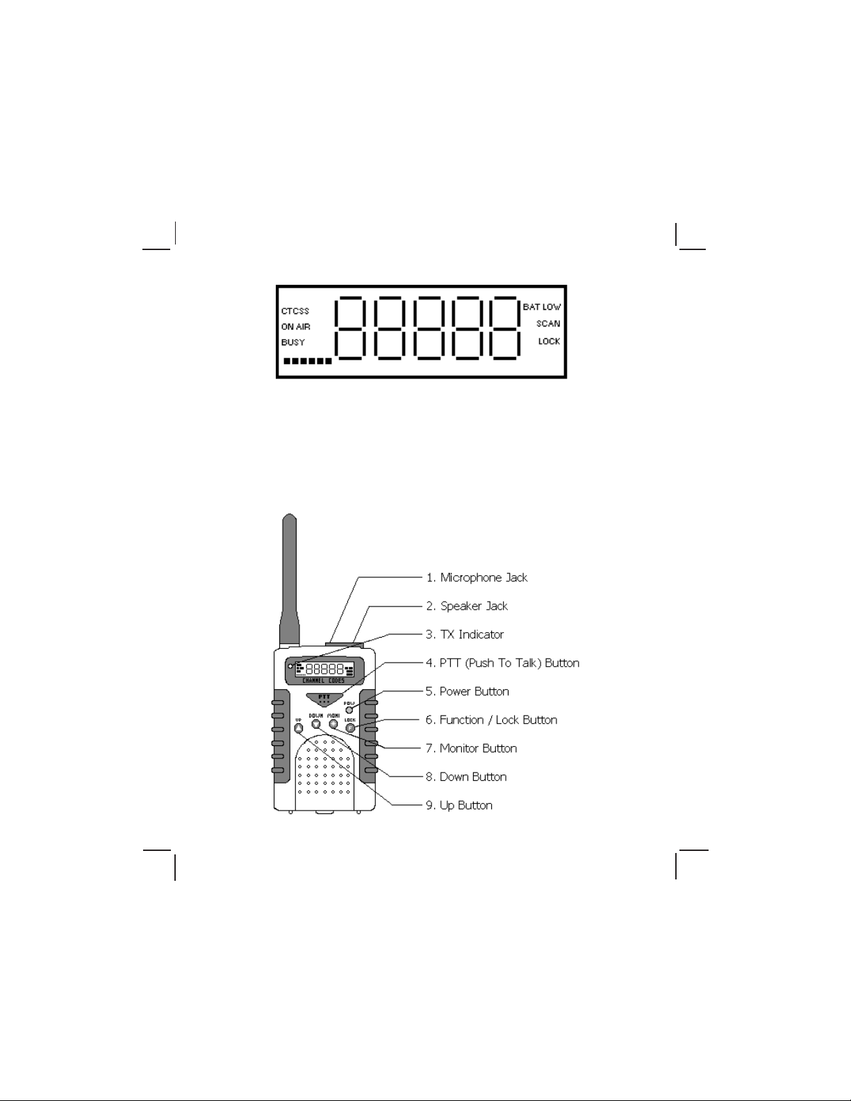
CTCSS Privacy Code System active
ON AIR Transmit mode active
BUSY Signal being received
BAT LOW Low battery voltage warning
SCAN Channel Scan in progress
CH Current channel
LOCK Tranciever settings locked
1
128-5379C
2 of 12
Page 3
Powering the transceiver:
Your FR-214 radio transceiver kit includes three rechargeable AA batteries (RBP-214)
and a charging station. You may operate your FR-214 using the rechargable batteries
included or you may use alkaline batteries. Alkaline batteries will provide slightly better
performance than the rechargable batteries.
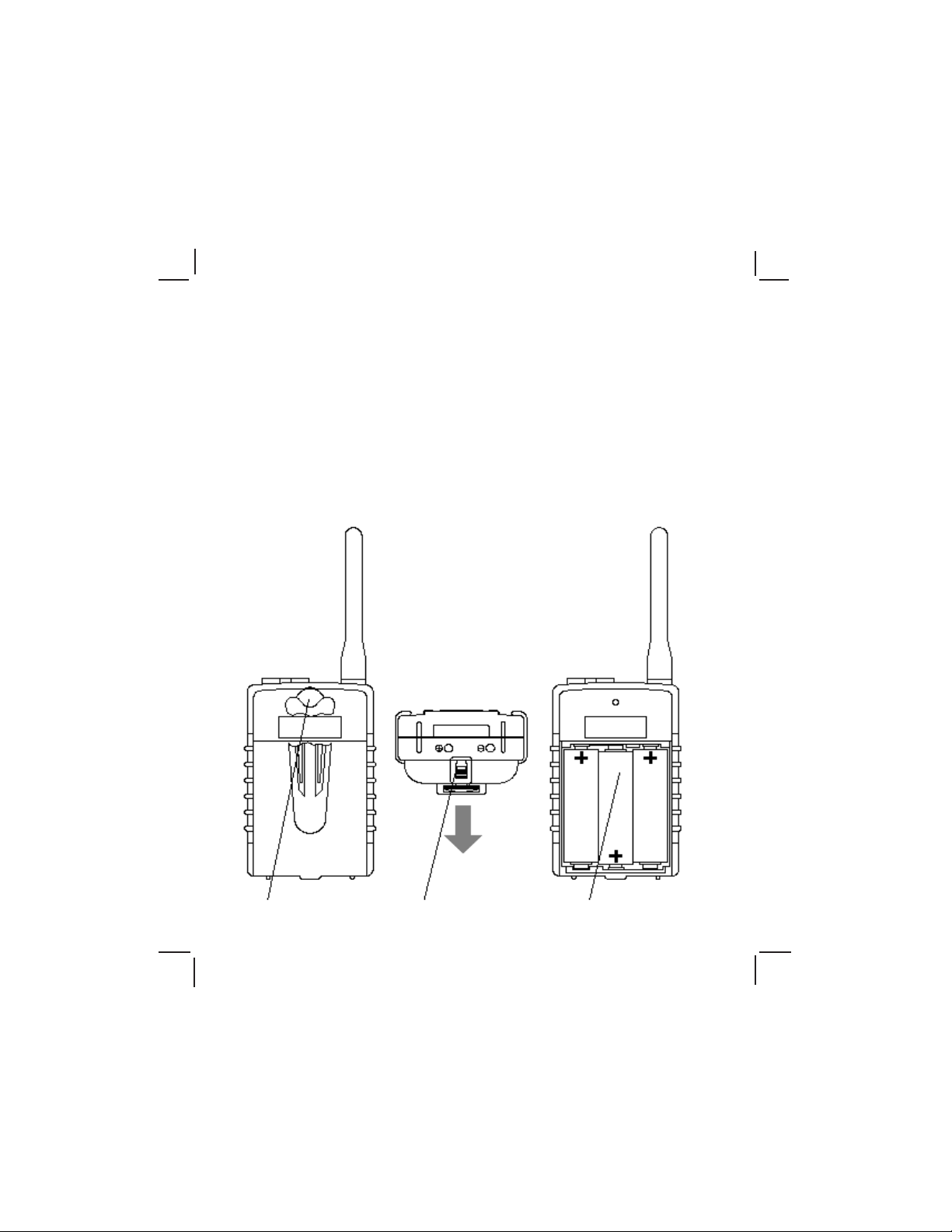
Installing the batteries:
To install batteries into the radio, it is necessary to remove the belt clip. To do this you
will need to rotate its thumbscrew counterclockwise. Next, release the battery
compartment lock on the bottom of the transceiver by sliding it outward. The battery
cover can now be removed by sliding it downward towards the bottom of the transceiver.
Observe the polarity symbols on the bottom of the tray when inserting the batteries and
replace the cover. Remember to lock the cover in place with the latch and replace the
belt clip.
1 Remove belt clip
thumbscrew
2 Release battery
cover lock
2
3 Insert batteries
128-5379C
3 of 12
Page 4
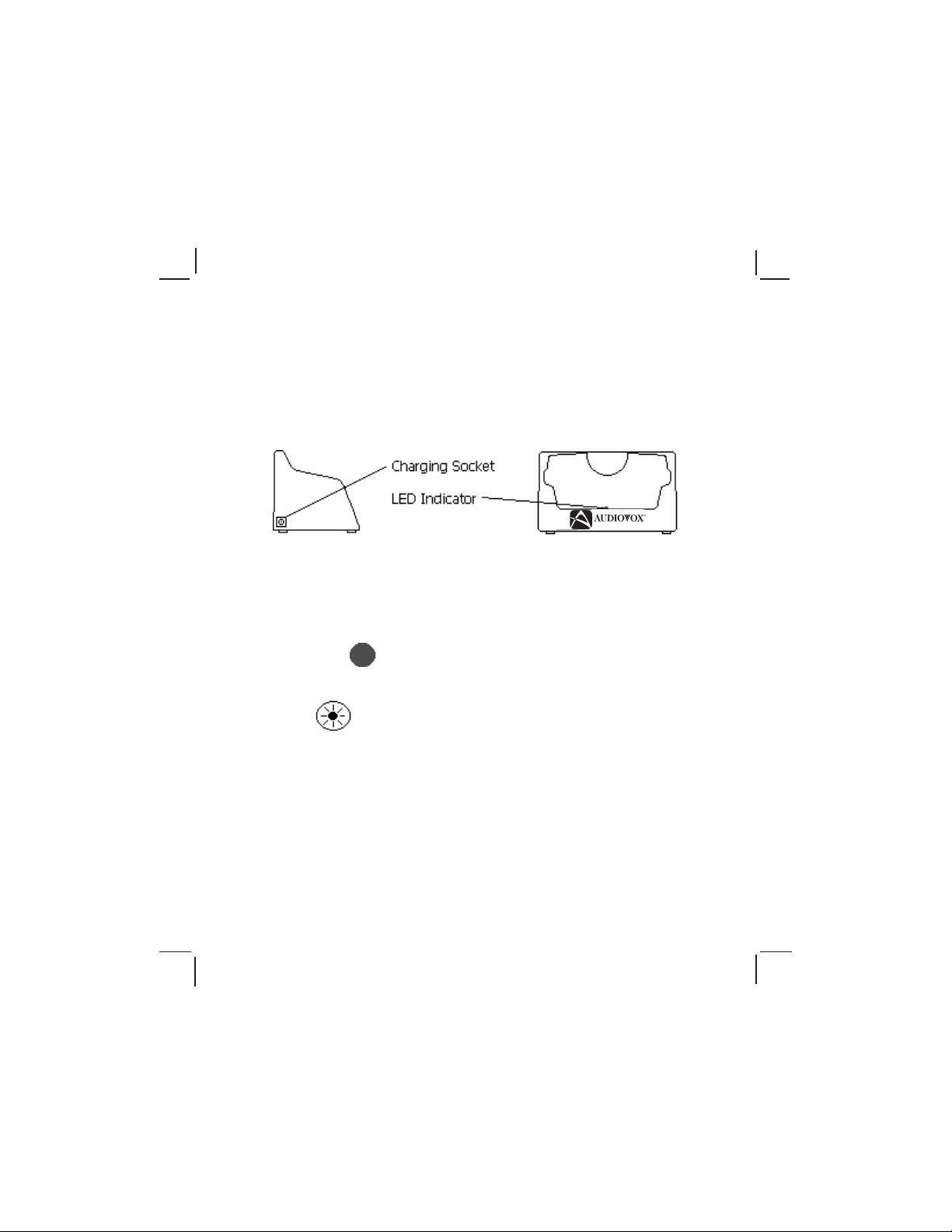
Charging the RBP-214 batteries:
Insert the charging adapter into a household electrical outlet and connect its power jack
to the socket at the lower rear corner of the charging stand. Simply placing the radio
into the charging stand will begin the charging process. The red LED in front serves as
a charge indicator. The LED will flash rapidly when charging weak or dead batteries.
As the batteries charge, the LED will flash at a slower rate. Fully charged batteries are
indicated by a rate of one flash every 10 seconds or slower. Approximitally 6 hrs are
required to fully charge the batteries. Remember to turn your FR-214 off before placing
it into the charging stand.
Important: The charging stand in your kit is intended for use with the RBP-214
batteries included in the kit. Do not attempt to recharge any other
batteries with the charging stand.
Operation:
POW Button: (red)
Press and hold this button for two seconds to turn the unit on. To turn the unit off, press
and hold the button for another two-second period.
MONI Button:
A momentary press of this button will illuminate the display for viewing in low light
conditions. The backlighting will remain on for five seconds. If any other buttons are
pressed while the backlighting is on, the display will remain lit for another five seconds.
This allows the light to remain on while the operator makes any necessary adjustments.
To check the current volume setting, press the “MONI” button for two seconds, while the
unit is on. If the volume is too high or too low, adjust it by using the up or down buttons
as required. There are 15 possible volume levels.
When a weak signal is being received by the transmitter (i.e. A voice becomes barely
audible), press the “MONI” button for two seconds. This bypasses the squelch setting
to temporarily allow very weak signals to be heard.
3
128-5379C
4 of 12
Page 5

UP and DOWN Buttons:
If these buttons are pressed before pressing the Lock/function button, a single press
will display the current volume setting and subsequent presses will change the volume
setting up or down.
Important: If a speaker/microphone or earphone is used, check the volume setting
before connecting it to the earphone jack. Be sure to set the volume low
at first, and then raise it to a comfortable level.
Lock/Function Button:
The Lock button allows the user to eliminate the possibility of accidentally changing the
transceiver’s selectable functions. Pressing and holding this button for two seconds will
activate the lock function. “LOCK” will be displayed in the lower right of the display,
indicating that the settings are locked in. While in the lock mode, it is still possible to
adjust the volume, however other settings will be fixed. T o unlock the transceiver simply,
press and hold the lock button for 2 seconds. While the unit is unlocked, you may
change any of the adjustable features by following the instructions that follow.
PTT (Push To Talk) Button:
Pressing and holding this button will allow you to speak to any transceiver that is set to
the same channel and privacy code setting as yours. Hold the transceiver approximately
3 to 5 inches from your face as you speak. After you have finished speaking, release
the PTT button to allow the reception of incoming signals. It is not possible to transmit
and receive at the same time. “ON AIR” will show on the left side of the display and the
red LED to the left of the display will illuminate while the PTT button is pressed.
Low Battery Warning:
“BATT LOW” will show in the upper right hand corner of the display as a warning of low
battery voltage. As the batteries become weak only the word “ON” instead of “ON AIR”
will show on the display when the PTT button is pressed.
Signal Strength Indicator (SSI):
The six dashed lines ------ on the lower left of the display indicate the strength of incoming
signals. Six lines represents a strong signal. One line indicates a weak signal. While
receiving a signal, one to six lines will be displayed indicating the strength of the signal.
While pressing the PTT button the signal strength indicator represents the strength of
the signal being transmitted.
4
128-5379C
5 of 12
Page 6

Setting the channel:
Press the Function/lock Button once
The channel number will flash on the display, indicated by “CH_xx.” Pressing the up or
down buttons, momentarily, within five seconds will increment or decrement through
the 14 channels one at a time.
Scan Mode:
While in channel setting mode, indicated by the channel number flashing, press and
hold the up or down buttons for 2 seconds to activate the Scan Mode. “Scan” will be
shown on the right side of the display. While in the scan mode the transceiver will
pause on active channels when receiving a transmission. Press the Lock or PTT
buttons momentarily to stop scanning channels.
Important: The Scan Mode will not operate if the squelch setting is on “00”
Setting the CTCSS (Continious Tone Coded Squelch System) privacy code:
Press the Function/lock button twice
The CTCSS privacy code will flash on the display indicated by “Ct-xx.” Pressing the up
or down buttons, within 5 seconds will change through the 38 CTCSS privacy codes
one at a time.
Using the CTCSS feature
Press the Function/lock button three times
5
128-5379C
6 of 12
Page 7

The display will show “Ctxxx”, indicating the status of the CTCSS mode as being on or
off. Pressing the up or down buttons, within 5 seconds will turn the CTCSS mode on or
off. When the CTCSS system is on, “CTCSS” will be shown in the upper right corner of
the display and the transceiver will only receive signals from other transceivers set to
the same channel and privacy code. When the CTCSS mode is off, the transceiver will
receive signals from all transceivers set to the same channel. Remember that the
CTCSS feature does not prevent others from listening to your transmissions. It only
allows your FR-214 to ignore signals from transceivers not set to the same privacy code.
Setting the squelch level
Press the function/lock button four times
The squelch setting will flash on the display, indicated by “SqL xx” Pressing the up or
down buttons within 5 seconds will change through the 7 squelch settings one at a
time. This setting determines the strength that an incoming signal must have in order
to be heard by the user. The higher the setting, the stronger the signal must be in order
for the user to hear it. If you desire to communicate with other trancievers in close
proximity, the squelch should be set high to eliminate unwanted weak signals. If the
transceiver is being used at extreme range, the squelch should be set low to allow
reception of weak signals. Setting the squelch to 00 will allow continuous reception of
all signals. Level 3 is recommended for normal use.
Turning the button beep tones on and off
Press the Function/Lock button five times
The display will show “bpxxx” Indicating the status of the button conformation beeps, on
or off. Pressing the up or down buttons, within 5 seconds will turn the button conformation
beeps on or off. When the beep tones are on, pressing the up, down or lock buttons will
be confirmed by a beep tone. A double beep tone will sound whenever the unit is turned
on or off. When the conformation beeps are off all beep tones will be eliminated.
6
128-5379C
7 of 12
Page 8

Scrolling to the beginning of the function setting mode
Press the Function/lock button six times
The channel number will flash on the display, beginning the function selection sequence
again. If the conformation beeps are on, a double tone will be heard.
Warning
Remove the batteries from the transceiver if it is not expected to be used for
•
long periods. This will eliminate the possibility of chemicals leaking from the
batteries and corroding the transceiver.
Avoid exposing the transceiver to water or extremes of temperature.
•
Do not use this device in or near a mining facility, which uses remotely
•
triggered explosives or in areas labeled “Blasting Area”. Premature or
accidental detonation may result.
Do not attempt to modify or in any way increase the output of this transceiver.
•
Its output is designed to meet the legal limits set by the F.C.C.
Do not use this device or change its batteries in potentially explosive atmospheres
as sparks in such areas could result in an explosion.
Turn your transceiver off wherever posted notices restrict the use of radios or
•
cellular telephones. Facilities such as hospitals may use equipment that is
sensitive to RF energy .
Turn your transceiver off on board aircraft when requested to do so.
•
Do not place your radio in front of a vehicle’s air-bag. If the air-bag deploys,
•
it could propel the transceiver like a projectile causing bodily injury .
This transceiver complies with F.C.C. regulations for use in the United States of
America. Use in other countries may be prohibited or restricted by local
regulation. Please check with the local regulating agency before using this
device outside the United States of America.
7
128-5379C
8 of 12
Page 9

Troubleshooting
Problem Possible cause Correction
No transmission Weak batteries Charge or replace batteries
while pressing Incorrect battery Install the batteries in the
the PTT button Polarity directions indicated by the
battery tray.
Weak or no Weak batteries Charge or replace batteries
signal received Channel and privacy Adjust the transceiver’s
code not set the same settings to match those settings
as target transceiver of the target transceiver
Volume level too low Increase volume level
PTT button inadvertently Release PTT button
depressed
Excessive radio Change to a different
interference on a channel
particular channel
Obstruction of radio Avoid operating in or near
signal large buildings or vehicles
Transceiver Batteries extremely Charge or replace batteries
beeps, but will discharged
not turn on when
Power button is
pressed
Reception of Squelch setting too low Increase the squelch level
unwanted signals CTCSS privacy mode Turn on the CTCSS privacy
not on mode and set code number to
match the setting of the
target transceiver.
Interference from Turn the devices off or move
electronic devices such farther away from them.
as computers or TVs
8
128-5379C
9 of 12
Page 10

Technical Specifications:
General
Frequency Range 462 - 467 MHz
Channels 14
Privacy Codes 38
Modulation Type FM ± 2.5 KHz
Power Supply 3 - 4.5VDC
Receiver
Sensitivity at 12dB Sinad .25 microvolts
Selectivity 45 dB
Distortion at 775 millivolts Audio Power 3% @775 milliwatts
Audio Frequency Response 400 – 3000 Hz
Transmitter
RF Output Power 500 milliwatts
Frequency Tolerance 0.00025%
Harmonic Suppression >50 dB
Channel Frequencies:
Channel Freq. MHz Channel Freq. MHz
1 462.5625 8 467.5625
2 462.5875 9 467.5875
3 462.6125 10 467.6125
4 462.6375 11 467.6375
5 462.6625 12 467.6625
6 462.6875 13 467.6875
7 462.7125 14 467.7125
9
128-5379C
10 of 12
Page 11

Continuous Tone Coded Squelch System Tone
Frequencies
CTCSS Freq. Hz CTCSS Freq. Hz
1 67.0 20 131.8
2 71.9 21 136.5
3 74.4 22 141.3
4 77.0 23 146.2
5 79.7 24 151.4
6 82.5 25 156.7
7 85.4 26 162.2
8 88.5 27 167.9
9 91.5 28 173.8
10 94.8 29 179.9
11 97.4 30 186.2
12 100.0 31 192.8
13 103.5 32 203.5
14 107.2 33 210.7
15 110.9 34 218.1
16 114.8 35 225.7
17 118.8 36 233.6
18 123.0 37 241.8
19 127.3 38 250.3
10
128-5379C
11 of 12
Page 12

90 DAY LIMITED WARRANTY
Applies to Audiovox Family Radio Service Products.
AUDIOVOX CORPORATION (the Company) warrants to the original retail purchaser of
this product that should this product or any part thereof, under normal use and
conditions, be proven defective in material or workmanship within 90 days from the date
of original purchase, such defect(s) will be repaired or replaced with new or reconditioned product (at the Company's option) without charge for parts and repair labor.
To obtain repair or replacement within the terms of this Warranty, the product is to be
delivered with proof of warranty coverage (e.g. dated bill of sale), specification of
defect(s), transportation prepaid, to the warranty center at the address shown below.
The Company disclaims liability for communications range of this product.
This Warranty does not apply to any product or part thereof which, in the opinion of the
Company, has suffered or been damaged through alteration, improper installation,
mishandling, misuse, neglect, accident, or by removal or defacement of the factory
serial number/bar code label(s). THE EXTENT OF THE COMPANY'S LIABILITY
UNDER THIS WARRANTY IS LIMITED TO THE REPAIR OR REPLACEMENT PROVIDED ABOVE AND, IN NO EVENT, SHALL THE COMPANY'S LIABILITY EXCEED
THE PURCHASE PRICE PAID BY PURCHASER FOR THE PRODUCT.
This Warranty is in lieu of all other express warranties or liabilities. ANY IMPLIED
WARRANTIES, INCLUDING ANY IMPLIED WARRANTY OF MERCHANTABILITY,
SHALL BE LIMITED TO THE DURATION OF THIS WRITTEN WARRANTY. ANY
ACTION FOR BREACH OF ANY WARRANTY HEREUNDER INCLUDING ANY IMPLIED WARRANTY OF MERCHANTABILITY MUST BE BROUGHT WITHIN A PERIOD
OF 30 MONTHS FROM DATE OF ORIGINAL PURCHASE. IN NO CASE SHALL THE
COMPANY BE LIABLE FOR ANY CONSEQUENTIAL OR INCIDENTAL DAMAGES
FOR BREACH OF THIS OR ANY OTHER WARRANTY, EXPRESS OR IMPLIED,
WHATSOEVER. No person or representative is authorized to assume for the Company
any liability other than expressed herein in connection with the sale of this product.
Some states do not allow limitations on how long an implied warranty lasts or the
exclusion or limitation of incidental or consequential damage so the above limitations or
exclusions may not apply to you. This Warranty gives you specific legal rights and you
may also have other rights which vary from state to state.
AUDIOVOX CORPORATION, 150 MARCUS BLVD., HAUPPAUGE, NEW YORK 11788
1-800-290-6650
128-5385A
© 1998 Audiovox Corporation, Hauppauge, N.Y. 11788
128-5379C
128-5379C
12 of 12
 Loading...