

Page 1
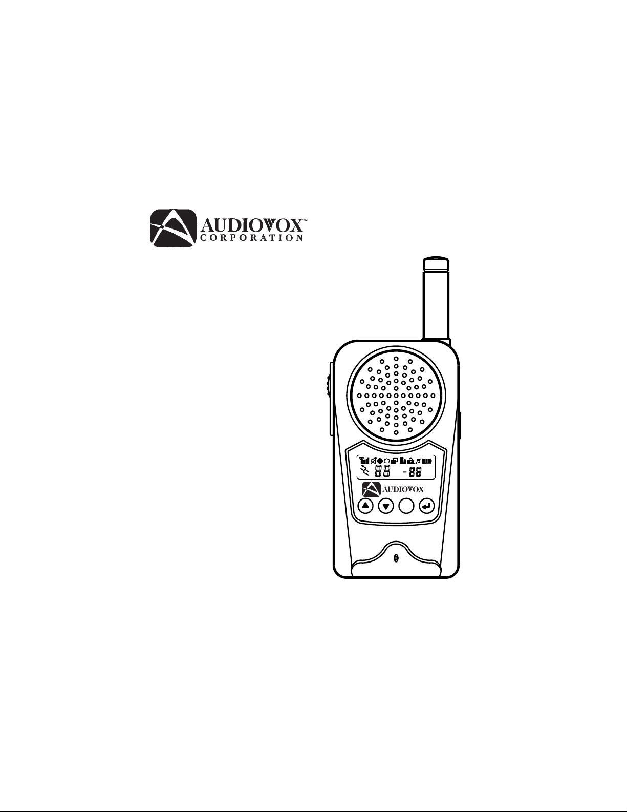
Model FR-1438-2
Owner’s Manual
F
FR1438-2
Page 2

5
3
1
4
PTT
M
2
11
F
10
FR1438-2
9
7
8
13
12
6
1. Battery Door
2. Monitor Button
3. Detachable Belt Clip
4. Push-To-Talk (PTT) Button
5. Antenna
6. External Speaker Jack
7. Built-in Speaker
8. Liquid Crystal Display (LCD)
9. Built-in Microphone
10. Up Button and Volume Control
1 1. Down Button and Volume Control
12. Function Button
13. Power On/Off and ENTER Button
2
Page 3
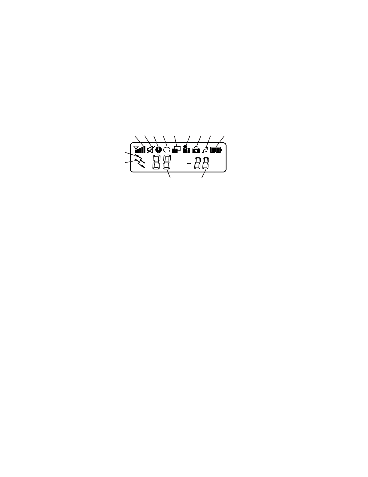
Model FR1438-2 DISPLAY
3 10, 119
68751, 2 4
12
13
14 15
1. RSSI Indicator: Receive signal strength indicator.
2. TX: Icon blinks during transmission.
3. Monitor Indicator: Icon appears when the monitor button is pressed.
4. Coded Tone Controlled Squelch System (CTCSS) Indicator: Icon appears
when receiving a transmission with correct CTCSS tone.
5. Auto Scan Indicator: Icon appears when the auto scan channel mode is
activated.
6. Dual Watch Scan Indicator: Blinks in dual watch scan mode or when the dual
watch scan mode is activated.
7. Voice Activated Transmission (VOX) Indicator: Blinks in the VOX selection
mode or appears when VOX is activated.
8. Key Lock Indicator: Blinks in autolock selection mode or appears when the
key lock is activated.
9. Call Indicator: This icon blinks in call selection mode and appears when the
unit is transmitting the call tone.
10. Battery Level Indicator: Icon indicates the battery charge strength.
11. Power Saver Indicator: Icon blinks to indicate the power saver is activated.
The rate at which the icon blinks varies with the power saving ratio. Fast
blinking indicates a lower power saving while slow blinking indicates a higher
power saving ratio.
12. TX Indicator: Icon appears when a signal is being transmitted.
13. RX Indicator: Icon appears when a signal is being received.
14. Large Segment Display: Indicates the channel number in use in normal mode.
When the Function Button is pressed, the FR1438-2 menu is displayed in
sequence.
3
Page 4

CH Channel select mode (1-14)
ctc Coded Tone Controlled Squelch System Sub-Channel Select Mode
SC Auto Channel Scan Mode
Dual Channel Watch Mode
d
UO Voice Activated Function
Udt Voice Activated Recovery Time
ALO Auto Key Lock Selection Mode
CAL Call Ringer Melody Selection Mode
ton Sub-Channel Number or Sub-Channel Frequency
15. Small Segment Display: Displays the CTCSS tone option in the normal mode.
The CTCSS option is shown in Hz.
When the Function Button is pressed, the FR1438-2 selection of each menu is
displayed in the following sequence and format.
(1 through 14) (CH) Channel Number
(1 through 38 or Frequency, OFF) (cTc) Sub-Channel Frequency in Hertz or
(Up, Down, OFF) (SC) Auto Channel Scan Mode
(Channel Number 1 through 14, OFF) (d
(High,Off, Low) (UO) Voice Activated Function
(Choice of 5,3,2,1 seconds) (Udt) Voice Recovery Activated Time
(Off, Auto) (ALO) Auto Key Lock Selection Mode
(1 Through 7) (CAL) Call Ringer Melody Selection
(Number) or (Hertz) (ton) Sub-Channel Frequency (Number = no,
Number
) Dual Channel Watch Mode
Frequency = Freq)
Powering the transceiver:
Your FR1438-2 radio transceiver operates on four AAA batteries . You may operate
your FR1438-2 using the rechargeable batteries included or you may use alkaline
batteries. Alkaline batteries will provide slightly better performance than the
rechargeable batteries, but must never be recharged in the charging stand.
Installing the batteries:
T o install batteries into the radio, it is necessary to remove the belt clip. To do this you
will need to release the spring clip securing the belt clip to radio and lift the belt clip
away from the radio body . Next, remove the battery compartment cover by sliding it
downward towards the bottom of the transceiver. Observe the polarity symbols on
the bottom of the tray when inserting the batteries. Replace the cover.
4
Page 5
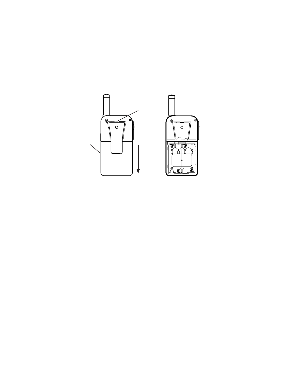
BATTERY
COVER
SPRING
CLIP
SIZE
AAA
SIZE
AAA
1.Press the spring clip
and slide the belt clip
upwards.
2. Slide the battery cover
downward.
3. Insert batteries observing
the polarity symbols on
the bottom of the tray.
The following guidelines will improve performance and provide longer operating times
for the FR1438-2:
1. Do not mix old and new batteries.
2. The use of alkaline-type batteries is recommended to provide the longest operating
time.
3. Do not mix alkaline, standard (carbon-zinc) or rechargeable (Ni-MH) batteries.
4. If the unit is not to be used for an extended period of time, remove the batteries. Old
or leaking batteries can cause damage to the unit and will void the warranty.
Wrist Strap and Detachable Belt Clip Installation
The wrist strap and detachable belt clip are provided to enable you to carry the FR1438-2
easily and safely. The wrist strap can be attached to the hole located on the top of the
belt clip. Feed the small loop on the end of the strap through the hole and then pass
the strap through the loop and pull tight.
The detachable belt clip fits into the slot located on the rear of the unit. T o remove the
belt clip, press the locking clip at the top of the belt clip away from the unit and slide
the belt clip upwards. To install the belt clip slide it down into the slot and snap in to
place.
5
Page 6

Charging the FR1438-2:
Insert the charging transformer into a household electrical outlet and connect its
power jack to the socket on the rear of the charging stand. Simply placing the unit
into the charging stand will begin the charging process. The red LED on the front of
the charging transformer serves as a charge indicator. The charging stand will
charge two units simultaneously. Approximately 12 – 16 hours are required to fully
charge the batteries. Remember to turn your FR1438-2 OFF before placing it into
the charging stand.
Caution: The charging stand in your kit is intended for use with the supplied
batteries. Do not attempt to recharge any other batteries with the
charging stand.
CHARGING
STAND
TRANSFORMER
CONNECTOR
CHARGING
TRANSFORMER
RED LED
CHARGING
INDICATOR
Controls:
Power On/Off (13):
Press and hold this button for two seconds to turn the unit on. A short confirming
melody will sound. To turn the unit off, press and hold the button for a two-second
period. A short tone will sound before the unit shuts off.
Enter Button (13):
This button is also used to confirm options for operating modes during the function
edit mode. A momentary press of this button will convert the display of the CTCSS
subcode from a frequency to a number or number to a frequency for two seconds.
6
Page 7

Push To Talk (PTT) Button (4):
Pressing and holding this button will allow you to speak to any transceiver that is set
to the same channel and privacy code setting as yours. Hold the transceiver
approximately 1 to 2 inches from your face as you speak into the built in microphone
(9). After you have finished speaking, release the PTT button to allow the reception
of incoming signals. It is not possible to transmit and receive at the same time. The
red transmit LED indicator located on the right side of the LCD Panel (8) will light
while the PTT button is pressed.
Releasing the button allows the unit to revert to standby mode. When receiving an
incoming signal, the green receive LED indicator on the left side of the LCD Panel (8)
will light.
The PTT button can also be used as a two-way call ringer. Pressing the button twice
quickly will call another party on the same channel. The word CALL and the transmit
icon will appear in the display. The user selected call will sound.
Volume Control (10 and 11):
In the standby mode, adjust the volume to a comfortable level by presing the Up (10)
to increase the volume level and the Down (11) to decrease the volume level.
Up Button (10):
In the standby mode, pressing this briefly will increase the volume. In the function
edit mode, pressing the button briefly will shift from the current option in each submenu
to next option in the same submenu.
Pressing the button for more than 1.5 seconds allows navigation at a more rapid
rate. In the standby mode the volume will increase rapidly. In the function mode,
different menus can be rapidly accessed.
Down Button (11):
In the standby mode, pressing this briefly will decrease the volume. In the function
edit mode, pressing the button briefly will shift from the current option in each submenu
to next previous option in the same submenu.
Pressing the button for more than 1.5 seconds allows navigation at a more rapid
rate. In the standby mode the volume will decrease rapidly. In the function mode,
different menus can be rapidly accessed.
7
Page 8

Function Button (12):
In the standby mode, pressing this button briefly will enter the function edit mode.
Pressing the button for more than 1.5 seconds will activate or deactivate the KEY
LOCK when the unit is in the standby mode. Refer to KEY LOCK function description
to activate and deactivate the KEY LOCK.
NOTE: All buttons will be disabled except for the Monitor Button (2) and the
PTT Button (4).
Monitor Button (2):
The Monitor Button is used to check the activity on a channel before transmitting.
When the Monitor Button is pressed, the LCD panel (8) will light and both the transmit
and the receive indicators will light. Pressing the Monitor Button during the edit function
mode will return the unit to standby. Pressing the Monitor Button during a VOX
tranmission (voice activated transmission) will discontinue the transmission and disable
the VOX function for ten seconds.
External Microphone/Speaker (6):
This jack accepts an Audiovox FRS-BHST headset/microphone for totally hands free
operation.
Operating Modes and Features
Channel Select Mode:
This feature allows the selection of main channels for communication.
1. Press the Function Button (12) until CH appears in the LCD Panel (8).
2. Press the Up Button (10) or the Down Button (11) to choose the channel.
3. Press the Enter (13) to confirm your selection.
Coded Tone Controlled Squelch System (CTCSS):
When the CTCSS feature is on the transceiver will only receive signals from other
transceivers set to the same channel and privacy code. When the CTCSS mode is
off, the transceiver will receive signals from all transceivers set to the same channel.
Remember that the CTCSS feature does not prevent others from listening to your
transmissions. It only allows your FR1438-2 to ignore signals from transceivers not set
to the same privacy code.
1. Press the Function Button (12) until ctc appears in the LCD Panel (8).
2. Press the Up Button (10) or the Down Button (11) to choose the CTCSS code desired.
3. Press the Enter (13) to confirm your selection.
8
Page 9

NOTE: T o communicate with other units, they must be switched to the same
channel and CTCSS subcode. T o communicate with other units that
do not have subcodes, switch your unit to the same channel with the
subcode set to Off.
AUTO CHANNEL SCAN MODE:
This feature allows scanning for an active channel. The volume cannot be adjusted
and the power saver is disabled in this mode. To access the Auto Channel Scan
menu:
1. Press the Function Button (I 2) until the auto channel icon blinks and SC appears
in the LCD Panel (8).
2. Press the Up Button (10) or the Down Button (11) to choose scanning up or
down from the current channel number.
3. Press the Enter Button (I 3) to confirm your selection.
The unit will begin scanning for an active main channel. If a transmission is
detected, the Receive and RSSI icons will appear in the LCD Panel (8). To turn off
the auto channel scan feature in the standby mode, simply press the Function
Button (12) once. You can pause on any channel while in the Auto Channel Scan
Mode by pressing the PTT Button (4) during the reception of a signal for 5 seconds
afterward. Pressing the Monitor Button (2) will resume scanning and eliminate that
channel from those being scanned.
DUAL WATCH SCAN MODE
This feature allows the monitoring of two different channels at the same time. If any
priority channel other than the current channel in use is preset, the preset channel
will be scanned every 0.5 second and you will signaled when a call is received.
While in the Dual Watch Scan Mode you may hear transmissions from either a
primary or secondary channel when transmitting. The unit will always transmit on
the primary channel unless the PTT Button (4) is pressed during or immediately
following the reception of secondary channel transmission. The power saver mode
is disabled in the Dual Watch Scan Mode and the volume is not adjustable. To
access the Dual Watch Scan menu:
1. Press the Function Button (12) until the dual watch icon blinks and d
the LCD Panel (8).
2. Press the Up Button (10) or the Down Button (II) to select the desired channel
number you wish to monitor.
3. Press the Enter Button (13) to confirm your selection.
9
appears in
Page 10

To turn off the dual watch feature in the standby mode, simply press the Function
Button (12) once.
VOX SELECTION MODE
The Voice Activated T ransmission (VOX) function allows your voice to activate signal
transmission automatically when the FR1438-2 is used with a hands free microphone/
headset (FRS-BHST). It also allows hands free use when a microphone/headset is
not being used without having to use the PTT Button (4). When in the VOX mode a
short beep will sound after the termination of any VOX generated transmission. To
access the VOX Selection menu:
1. Press the Function Button (12) until the VOX icon blinks and UO appears in the
LCD Panel (8).
2. Press the Up Button (10) or the Down Button (11) to select from high, low or off.
The high or low setting determines VOX response sensitivity.
3. Press the Enter Button (13) to confirm your selection.
VOX RECOVERY TIME SELECTION MODE
This allows the setting of the transmit delay after you have finished speaking.
To access the VOX Recovery Time Selection menu:
1. Press the Function Button (12) until Udt appears in the LCD Panel (8) with
the VOX icon blinking.
2.Press the Up Button (10) or the Down Button (1 1) to select from the 5, 3, 2
or 1 second setting. This setting determines the delay time between
transmitting and receiving.
3.Press the Enter Button (13) to confirm your selection.
NOTE: You may need to try different VOX time settings to dete rmin e
the best value to suit your speaking habits.
T o turn of f the VOX feature, enter the VOX selection mode and
then select OFF.
AUTO KEY LOCK SELECTION MODE
This feature prevents accidental channel change and disturbance to the preferred
settings of the FR1438-2. The Auto Key Lock feature temporarily disables the Up,
Down and Enter Buttons. To access the Auto Key Lock Selection menu:
1. Press the Function Button (12) until the auto lock icon blinks and ALO
appears in the LCD panel (8).
10
Page 11

2. Press the Up Button (10) or Down Button (11) to select the Auto option.
3. Press the ENTER key to confirm your selection.
If you do not press any key for more than 15 seconds in the standby mode,
keys will automatically be locked except the PTT (4) and monitor (2) buttons.
To turn the auto key lock on or off in standby mode, simply press and hold the
Function Button (12) for more than 1.5 seconds. To quickly activate the Key
Lock, hold the Function Button (12) for more than 1.5 seconds.
CALL MELODY SELECTION MODE
This feature provides seven user selectable call ringer melodies that alert the user
that a calling party wishes to communicate with them. Once the melody is chosen,
double pressing the PTT Button (4) twice within one second will transmit the tone
selected. To select your favorite Call Ringer melody:
1. Press the Function Button (12) until the call icon blinks and CAL appears in
the LCD panel (8).
2. Press the Up Button (10) or Down Button (11) to preview the seven
ava ila ble melodies.
3. Press the ENTER key to confirm your selection.
CTCSS SUB CODE DISPLAY SELECTION MODE
To select your favorite CTCSS sub code display:
1. Press the Function Button (12) until Ton appears in the LCD panel (8).
2. Press the Up Button (10) or Down Button (11) to select the tone in Hertz or
the tone ID number.
3. Press the ENTER key to confirm your selection.
NOTES FOR GOOD COMMUNICATION
1 . The FR1438-2 14 channels are shared on a ‘take turns’ basis. This means
other groups may be talking on any of the channels. A common code of
ethics/courtesy is to switch to another vacant channel and not to attempt to
talk over someone who is already using the channel you first selected.
2. The FR1438-2 has been designed to maximize performance and improve
transmission range in the field. To avoid interference, it is recommended that
you do not use the units closer than 5 feet apart.
3. For best transmission results, always keep your mouth about 2-3 inches from
the microphone (9) and speak slowly in a normal voice.
11
Page 12

Warning
Remove the batteries from the transceiver if it is not expected to be used for long
•
periods. This will eliminate the possibility of chemicals leaking from the batteries
and corroding the transceiver.
Avoid exposing the transceiver to water or extremes of temperature.
•
Do not use this device in or near a mining facility, which uses remotely triggered
•
explosives or in areas labeled “Blasting Area”. Premature or accidental detonation
may result.
Do not attempt to modify or in any way increase the output of this transceiver. Its
•
output is designed to meet the legal limits set by the F.C.C.
Do not use this device or change its batteries in potentially explosive atmospheres
•
as sparks in such areas could result in an explosion.
Turn your transceiver off wherever posted notices restrict the use of radios or cellular
•
telephones. Facilities such as hospitals may use equipment that is sensitive to
RF energy.
Turn your transceiver off on board aircraft when requested to do so.
•
Do not place your radio in front of a vehicle’s air-bag. If the air-bag deploys, it
•
could propel the transceiver like a projectile causing bodily injury.
This transceiver complies with F.C.C. regulations for use in the United States of
America. Use in other countries may be prohibited or restricted by local regulation.
Please check with the local regulating agency before using this device outside
the United States of America.
Main Channel Frequencies:
Channel Freq. MHz Channel Freq. MHz
1 462.5625 8 467.5625
2 462.5875 9 467.5875
3 462.6125 10 467.6125
4 462.6375 11 467.6375
5 462.6625 12 467.6625
6 462.6875 13 467.6875
7 462.7125 14 467.7125
12
Page 13

Troubleshooting
Problem Possible cause Correction
No transmission Weak batteries Charge or replace batteries
while pressing Incorrect battery Polarity Install the batteries in the
the PTT button directions indicated by the
battery tray.
Weak or no Weak batteries Charge or replace batteries
signal received Channel and privacy Adjust the transceiver’s
code not set the same settings to match those settings
as target transceiver of the target transceiver
Volume level too low Increase volume level
PTT button inadvertently Release PTT button
depressed
Excessive radio interference Change to a different
on a particular channel channel
Obstruction of radio Avoid operating in or near
signal large buildings or vehicles
Transceiver Batteries extremely Charge or replace batteries
beeps, but will discharged
not turn on when
Power button is
pressed
Reception of CTCSS privacy mode Turn on the CTCSS privacy
unwanted signals not on mode and set code number to
match the setting of the
target transceiver.
Interference from Turn the devices off or move
electronic devices such farther away from them.
as computers or TVs
13
Page 14

Technical Specifications:
General
Frequency Range 462.5625 - 467.7125 MHz
Channels 14
Privacy Codes 38 for each main channel
Channel Spacing 12.5 kHz
Dimensions (W x H x D) 50.6mm x 95.5mm x 26.0mm
Power Supply
Power Source Alkaline Batteries, AAA
(4), 6 VDC
NiMH rechargeable, AAA
(4), 4.8 VDC
Operating Time (Tx: Rx: Stdby) About 36 hours (5: 5: 90 ratio)
(Based on alkaline batteries)
Receiver
Useable Sensitivity -121 dBm Minimum
Maximum Audio Output Power 150 mW Minimum
Audio Distortion 5% Maximum
Transmitter
RF Output Power 500 mW Maximum (6V)
Range Up to 2 miles
Maximum Deviation +/- 2.5 kHz
Audio Distortion 5% Maximum
14
Page 15

Continuous Tone Coded Squelch System Tone
Frequencies (in Hz)
CTCSS Freq. Hz CTCSS Freq. Hz
1 67.0 20 131.8
2 71.9 21 136.5
3 74.4 22 141.3
4 77.0 23 146.2
5 79.7 24 151.4
6 82.5 25 156.7
7 85.4 26 162.2
8 88.5 27 167.9
9 91.5 28 173.8
10 94.8 29 179.9
1 1 97.4 30 186.2
12 100.0 31 192.8
13 103.5 32 203.5
14 107.2 33 210.7
15 110.9 34 218.1
16 114.8 35 225.7
17 118.8 36 233.6
18 123.0 37 241.8
15
Page 16

90 DAY LIMITED WARRANTY
Applies to Audiovox Family Radio Service Products.
AUDIOVOX CORPORATION (the Company) warrants to the original retail
purchaser of this product that should this product or any part thereof, under
normal use and conditions, be proven defective in material or workmanship within
90 days from the date of original purchase, such defect(s) will be repaired or
replaced with new or reconditioned product (at the Company's option) without
charge for parts and repair labor.
To obtain repair or replacement within the terms of this Warranty, the product is
to be delivered with proof of warranty coverage (e.g. dated bill of sale),
specification of defect(s), transportation prepaid, to the warranty center at the
address shown below.
The Company disclaims liability for communications range of this product.
This Warranty does not apply to any product or part thereof which, in the opinion
of the Company, has suffered or been damaged through alteration, improper
installation, mishandling, misuse, neglect, accident, or by removal or defacement
of the factory serial number/bar code label(s). THE EXTENT OF THE COMPANY'S
LIABILITY UNDER THIS WARRANTY IS LIMITED TO THE REPAIR OR REPLACEMENT PROVIDED ABOVE AND, IN NO EVENT, SHALL THE COMPANY'S
LIABILITY EXCEED THE PURCHASE PRICE PAID BY PURCHASER FOR THE
PRODUCT.
This Warranty is in lieu of all other express warranties or liabilities. ANY IMPLIED
WARRANTIES, INCLUDING ANY IMPLIED WARRANTY OF MERCHANTABILITY, SHALL BE LIMITED TO THE DURATION OF THIS WRITTEN WARRANTY.
ANY ACTION FOR BREACH OF ANY WARRANTY HEREUNDER INCLUDING
ANY IMPLIED WARRANTY OF MERCHANTABILITY MUST BE BROUGHT
WITHIN A PERIOD OF 30 MONTHS FROM DATE OF ORIGINAL PURCHASE.
IN NO CASE SHALL THE COMPANY BE LIABLE FOR ANY CONSEQUENTIAL
OR INCIDENTAL DAMAGES FOR BREACH OF THIS OR ANY OTHER WARRANTY, EXPRESS OR IMPLIED, WHATSOEVER. No person or representative
is authorized to assume for the Company any liability other than expressed herein in
AUDIOVOX CORPORATION, 150 MARCUS BLVD., HAUPPAUGE, NEW YORK 11788
© 2000 Audiovox Corporation, Hauppauge, N.Y. 11788
1-800-290-6650
128-5385A
128-5728A
 Loading...