

Page 1
Owner’s ManualOwner’s Manual
Owner’s Manual
Owner’s ManualOwner’s Manual
Model FR-114-2Model FR-114-2
Model FR-114-2
Model FR-114-2Model FR-114-2
TT
ww
T
TT
w
ww
o Wo W
o W
o Wo W
aa
a
aa
y Fy F
amily Radioamily Radio
y F
amily Radio
y Fy F
amily Radioamily Radio
Customer Service
1-800-645-4994
Page 2

CONGRA TULA TIONS ON YOUR SELECTION
OF THE FR-114-2 (F AMIL Y RADIO)
It is one of the most sophisticated and reliable two way family
radios available.
BEFORE OPERA TING YOUR FR-1 14-2 (F AMIL Y RADIO)
READ THIS MANUAL CAREFULL Y
-1-
Page 3
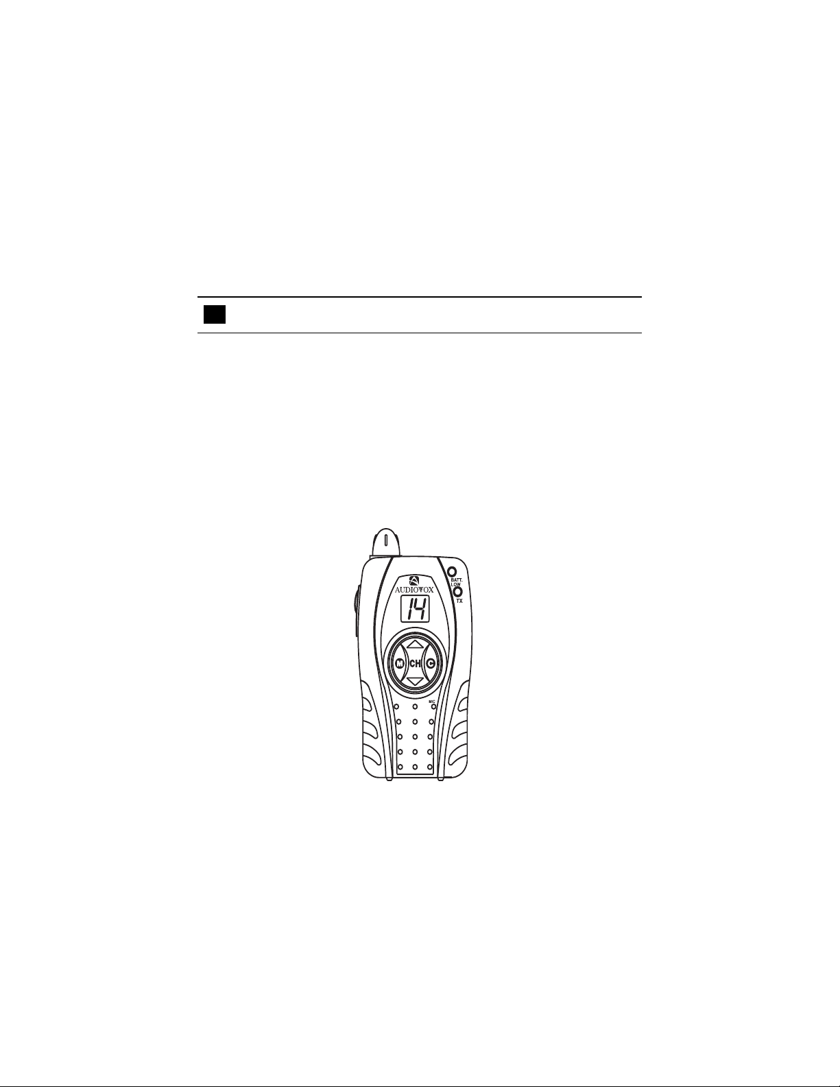
FEATURES
Your FR-1 14-2 Family Radio is a portable, easy to use, two-way radio that
you can carry almost anywhere. It is skillfully constructed to give you reliable
communications for many different applications. The FR-114-2 is ideal for
use around the house, in your car or boat, on hunting and camping trips, on
the ski slopes or at the mall. Y ou can also use the FR-114-2 Family Radio
for business for security patrols or warehouse communications.
Advanced Phase Lock Loop (PLL) circuitry achieves a new technique for
generating all the required frequencies with fewer crystals. The result is
much tighter frequency control and superior reliability .
-2-
Page 4

PERFORMANCE
Y our transceiver will achieve its maximum operating range when communicating
with other transciever(s) in a flat open area with no trees or buildings
obstructing its signal. Range may be up to two miles under such conditions.
Obstacles such as buildings, trees or mountains will tend to reduce the
transceiver’s effective range.
FCC WARNING
Replacement or substitution of transistors, diodes or other parts of a unique
nature, with parts other than those recommended by the manufacturer, may
cause a violation of the technical regulations of Part 95 of FCC Rules or
violation of type acceptance requirements of Part 2 of the rules.
-3-
Page 5
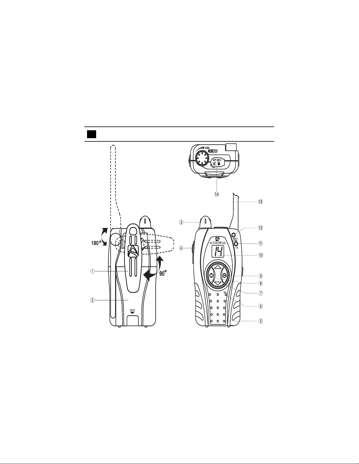
FUNCTION AND LOCA TION OF THE CONTROLS
-4-
Page 6

1. Belt Clip
2. Battery Compartment
3. POWER ON /OFF-VOLUME CONTROL: Rotate clockwise to turn
on the transceiver and increase the listening volume level.
4. Push-to-T alk Button (PTT): Press to transmit. Release to receive.
5. Speaker
6. Microphone
7. Monitor Button (M): Press and hold to monitor channel activity .
8-1. Channel Up Button (CH ): Pressing this button momentarily
advances 1 channel. Holding the button will continuously advance
channels until the button is released.
8-2. Channel Down Button (CH ): Pressing this button momentarily
decreases 1 channel. Holding the button will continuously decrease
the channels number until the button is released.
9. Call Button: Press to send a ri ngi ng s ound to other radios tuned
to the same channel.
10. Channel Display: Displays the channel selected (1-14).
11. Transmit Indicator (TX): Illuminates while transmitting.
12. Low Battery Indicator (BATT. LOW): Illuminates when the
battery charge is low .
13. Antenna: Rotate clockwise to the full upright position for maximum
range when the transceiver is in use.
14. Speaker/Microphone Jack (SP/MIC): For use with an external
headset accessory.
-5-
Page 7

LED DISPLAY AND OPERATION
2
1
3
The FR-114-2 is equipped with an LED display to indicate its settings
and functions. Pressing the Push-to-T alk (PTT), monitor , channel select or
call buttons, will illuminate the display. The display will remain lit for 5
seconds after any of these buttons is pressed.
1. Illuminates green when transmitting
2. Illuminates red when the battery power is low.
3. 14 Displays the current channel number (1 to 14).
-6-
Page 8

BATTER Y INST ALLA TION
Your FR-114-2 requires four “AAA” alkaline cells. Alkaline
batteries will provide the best performance from your
transceiver. Remove the battery cover by rotating the belt
clip away from the battery compartment. Remove the
battery cover by releasing the clasp at the bottom of the
compartment. Slide the battery cover downward. Observe
the polarity symbols inside the battery tray when installing
the batteries.
CAUTION:
Incorrect battery installation can damage the unit.
BATTER Y SA VER MODE
Y our FR-1 14-2 has a unique circuit designed to dramatically extend the life of
its batteries. After five seconds of inactivity, the FR-1 14-2 will switch to battery
saver mode and the display will turn off to conserve battery life. While in
battery saver mode, the transceiver will remain ready to receive any incoming
transmissions. Pressing any of the buttons will exit the battery saver mode
and illuminate the display .
-7-
Page 9

USING YOUR FR-114-2
T urning the T ransceiver on
Rotate the POWER ON /OFF-VOLUME CONTROL clockwise to
turn on the transceiver and increase the listening volume level. The speaker
will play a confirmation beep tone to confirm the transceiver’s activation. T o
turn the unit off, rotate the POWER ON /OFF-VOLUME CONTROL
counterclockwise.
Button Conformation T ones
Whenever, the Channel Up Button (CH ) or Channel Down Button
(CH ) buttons are pressed, the speaker will play a tone to confirm each
press. When adjusting the channel number, the tone will correspond to the
current setting, the lower the tone, the lower the channel selected.
Low Battery Alert
When the batteries are in need of replacement, the low battery indicator
LED will light.
-8-
Page 10

T o Select a Channel
Press and release the Channel Up
Button (CH ) or the Channel
Down Button (CH ). To select the
Up Button
desired channel from 1 to 14. A
unique tone will be played to confirm
each channel selected and the
Down Button
current channel setting will be shown
on the display. When the highest or
lowest channel is reached, the
channel setting will wrap around and
repeat the selection. Holding the up
or down buttons will rapidly , advance
through the channels.
Call Button
Call Signals
When the call button is pressed, the FR-114-2 will transmit a threesecond ringing sound to other transceiver’s tuned to the same channel.
This feature can be used to signal other parties that voice communication is
desired.
-9-
Page 11

T o Transmit
1. Turn the POWER ON /OFF-VOLUME CONTROL clockwise to the on
position.
2. If the battery low (BATT. LOW) indicator is on, replace the batteries.
3. Select the desired channel.
4. Press and hold the Push-to-Talk Button (PTT) button while speaking
slowly and clearly in a normal voice, approximately 2 to 3 inches from
the microphone. A built-in modulation control circuit will automatically
adjust the microphone input level. There is no need to speak loudly .
5. The transmit indicator will illuminate while transmitting.
6. Release the Push-to-Talk Button (PTT) button when you finish
speaking to receive incoming signals.
T o Receive
1. Turn the POWER ON /OFF-VOLUME CONTROL clockwise to the on
position.
2. If the battery low (BATT. LOW) indicator is on, replace the batteries.
3. Select the desired channel.
4. Adjust the POWER ON /OFF-VOLUME CONTROL clockwise to
increase the listening volume to the desired level.
5. The transceiver will play strong received signals through its internal
speaker or through a headset if so equipped.
Monitor Function
The monitor button can be used to listen to all signals present on a channel.
This is useful when communicating with other parties at extreme range.
-10-
Page 12

WARNING
n Remove the batteries from the transceiver if it is not expected to
be used for long periods. This will eliminate the possibility of battery
acid leaking from the batteries and corroding the transceiver.
n Avoid exposing the transceiver to water or extremes of tempera-
ture.
n Do not use this device in or near a mining facility, which uses
remotely triggered explosives or in areas labeled “Blasting Area”.
Premature or accidental detonation may result.
n Do not attempt to modify or in any way increase the output of this
transceiver. Its output is designed to meet the legal limits set by
the FCC.
n Do not use this device or change its batteries in potentially explosive
atmospheres as sparks in such areas could result in an explosion.
n Turn your transceiver off wherever posted notices restrict the use
of radios or cellular telephones. Facilities such as hospitals may
use equipment that is sensitive to RF energy .
n Turn your transceiver off on-board aircraft when requested to do so.
n Do not place your transceiver in front of a vehicle’s air-bag. If the
air-bag deploys, it could propel the transceiver like a projectile.
n This transceiver complies with F.C.C. regulations for use in the
United States. Use in other countries may be prohibited or
restricted by local regulation. Please check with the local regulating
agency before using this device outside of the United States.
-11-
Page 13

SPECIFICATIONS*
Channels: 14
Output Power: 500 mW ERP
Battery Life:
Alkaline (Preferred): 23 Hours (1050mA)
NiCD 6.5 Hours (300mA)
Power Source (Alkaline): 6.0 VDC
* These specifications are subject to change and improvement
without notice. They represent typical values, individual units
may vary.
Channel Frequencies:
Channel MHz Channel MHz
1 462.5625 8 467.5625
2 462.5875 9 467.5875
3 462.6125 10 467.6125
4 462.6375 11 467.6375
5 462.6625 12 467.6625
6 462.6875 13 467.6875
7 462.7125 14 467.7125
-12-
Page 14

90 DAY LIMITED WARRANTY
Applies to Audiovox Family Radio Service Products.
AUDIOVOX CORPORATION (the Company) warrants to the original retail
purchaser of this product that should this product or any part thereof, under
normal use and conditions, be proven defective in material or workmanship
within 90 days from the date of original purchase, such defect(s) will be
repaired or replaced with new or reconditioned product (at the Company's
option) without charge for parts and repair labor.
To obtain repair or replacement within the terms of this Warranty, the product
is to be delivered with proof of warranty coverage (e.g. dated bill of sale),
specification of defect(s), transportation prepaid, to the warranty center at the
address shown below.
The Company disclaims liability for communications range of this product.
This Warranty does not apply to any product or part thereof which, in the
opinion of the Company, has suffered or been damaged through alteration,
improper installation, mishandling, misuse, neglect, accident, or by removal or
defacement of the factory serial number/bar code label(s). THE EXTENT OF
THE COMPANY'S LIABILITY UNDER THIS WARRANTY IS LIMITED TO THE
REPAIR OR REPLACEMENT PROVIDED ABOVE AND, IN NO EVENT,
SHALL THE COMPANY'S LIABILITY EXCEED THE PURCHASE PRICE
PAID BY PURCHASER FOR THE PRODUCT.
This Warranty is in lieu of all other express warranties or liabilities. ANY
IMPLIED WARRANTIES, INCLUDING ANY IMPLIED WARRANTY OF
MERCHANTABILITY, SHALL BE LIMITED TO THE DURATION OF THIS
WRITTEN WARRANTY. ANY ACTION FOR BREACH OF ANY WARRANTY
HEREUNDER INCLUDING ANY IMPLIED WARRANTY OF MERCHANTABILITY
MUST BE BROUGHT WITHIN A PERIOD OF 30 MONTHS FROM DATE OF
ORIGINAL PURCHASE. IN NO CASE SHALL THE COMPANY BE LIABLE FOR
ANY CONSEQUENTIAL OR INCIDENTAL DAMAGES FOR BREACH OF THIS
OR ANY OTHER WARRANTY, EXPRESS OR IMPLIED, WHATSOEVER. No
person or representative is authorized to assume for the Company any liability
other than expressed herein in connection with the sale of this product.
AUDIOVOX CORPORATION, 150 MARCUS BLVD., HAUPPAUGE, NEW YORK 11788
1-800-645-4994
-13-
128-5385
Page 15

128-5724© 2000 Audiovox Corporation, 150 Marcus Blvd., Hauppauge, NY 11788
 Loading...