

Page 1
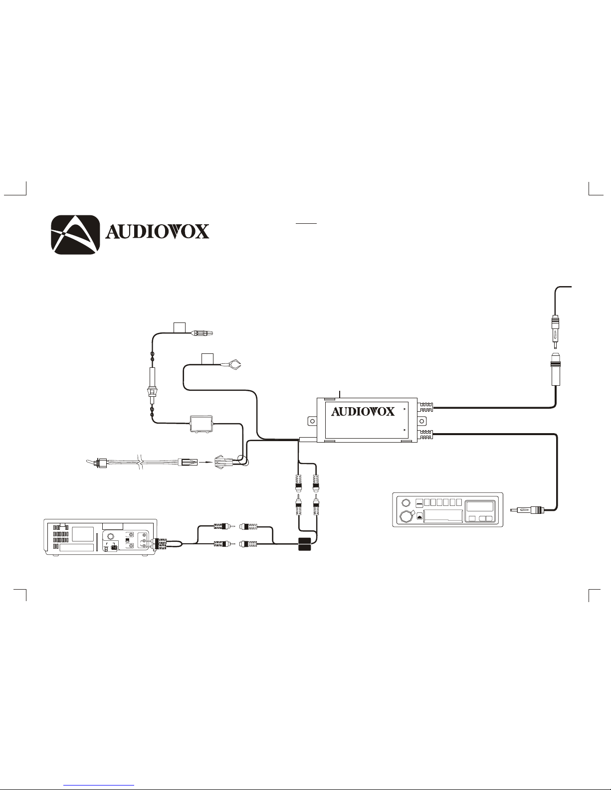
FM Modulator /
Isola tion Trans former
C onnections
and
Ins tallation
Ins truc tions
NO TE
1. The Vehicle a ntenna is cut off from the radio when
the power is supplied to the FM modulator via S W1.
P ower to the modulator mus t be switched off in
order to rec eive normal AM/FM rece ption.
2. The FM modula tor is designed to ac cept “Line Level”
s ignals only. T hese “s ignals ” require amplifica tion to
drive hea dphones or s peakers . ( Inputting “H igher”
level audio signals (hea dphone, external spea ker etc)
will override the radio a nd caus e unwanted noise.
R educ ing higher level inputs ca n be achieved through
the use of s pecia l “ attenua tors” or line level reduc ers. )
3. S W2 is used to s elect the modula tor frequency. T he
ra dio mus t be turned to the same frequenc y that was
s elec ted by Switch S W2.
FUSE
125V 2A
DC 12V
-
+
-
+
RF
OUT
ANT.
IN
CH. 3
CH. 4
VIDEO
AUDIO
R CA PATC H C OR D R E QUIR E D F OR S TE RE O CO NNE C TION
Y-ADAP TE R R E QUIR ED FO R MON O C ON NE CT ION (6 ”)
R ED R CA TO RIG HT
WH ITE R CA TO LE FT
G RO UND
+ 12 ACC PO WE R
DWNUP
BAND
1 2 3 4 5 6
TONE
OFF/VOL
XXXX/XXXXXX
AS/FS
T/F
▲
▲
TO R ADIO
ANT EN NA I N
TO VE HIC LE
ANT EN NA O UT
36”
36”
7.5”
15’
18”
18”
S W1
36”
128-6 818
FM S TE R EO MO DU LAT OR
89.1/88 .7 MH z
132-56 72
TO RADIO ANT. TO CAR ANT.
®
ELEC TRO NIC S C O RP.ELEC TRO NIC S C O RP.
S W 2
Da te : 22 /4/03P RI NTI NG : AL L IN B LAC K WOR DI NG S, WHI TE B ASE
Wi th indiv idua l Is ola tion Tr ans for mer
 Loading...