

Page 1
FM Pro
Powered Indoor Antenna
FM-50
OWNER’S MANUAL
T0100-FMPRO-OM.qxp 3/26/03 12:45 PM Page C1
Page 2
Important Safety Precautions
Use extreme caution when installing or removing
an outdoor antenna close to overhead wires.
If the antenna starts to fall, let it go! If any part of
the antenna makes contact with overhead power lines,
touching the antenna or the antenna cable can cause
electrocution and death. Call the power company
to remove the antenna. Do not attempt to remove
it yourself!
FM-50
1
T0100-FMPRO-OM.qxp 3/26/03 12:45 PM Page C2
Page 3
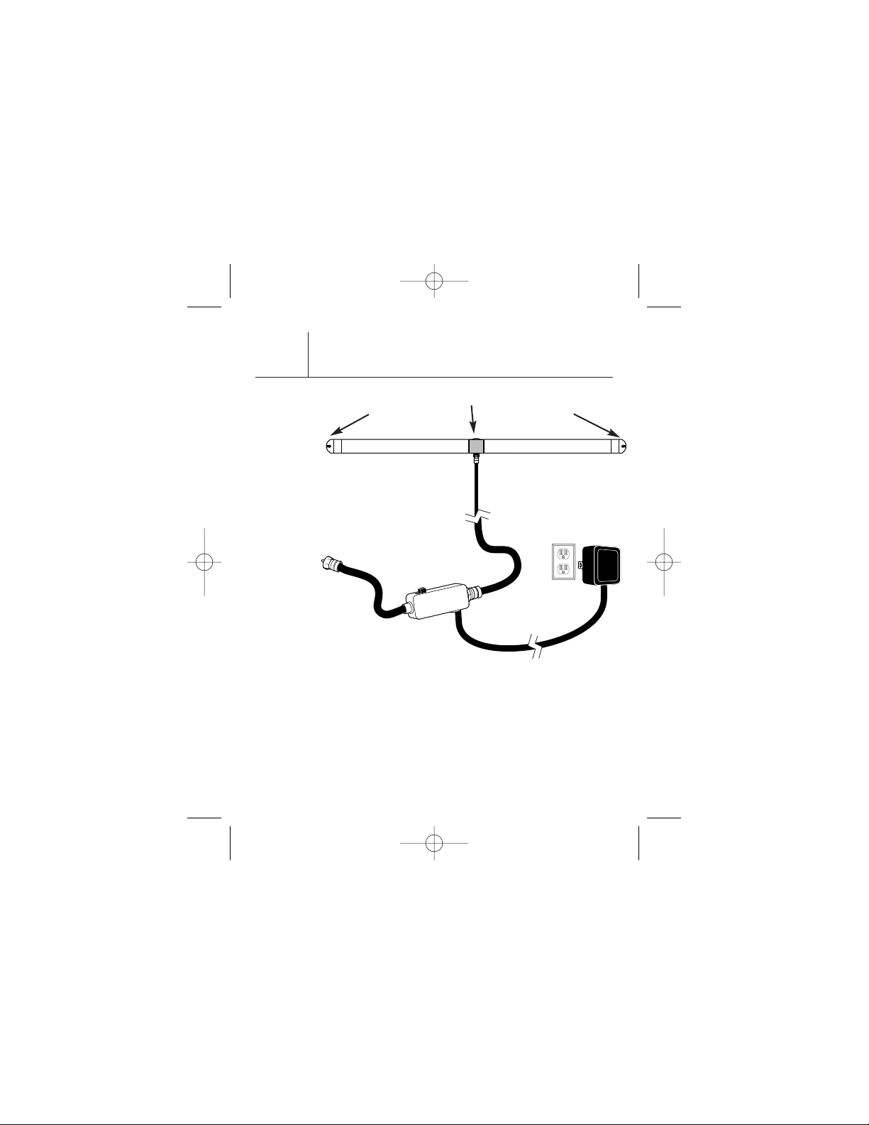
Installing Your FM Pro
When mounting the antenna outdoors or indoors,
remember to install the FM Pro HORIZONTALLY, parallel
to the ground. DO NOT INSTALL FM PRO VERTICALLY!
NOTE: The FM Pro may be painted to match the decor of
your home. We recommend using a primer coat before
applying your color coat. Do not use a lead-based paint.
FM-50
2
To FM Antenna In
OFF/ON
TO
RECIVER
TO
ANTENNA
Screw
Screw
Screw
Fig. 4
T0100-FMPRO-OM.qxp 3/26/03 12:45 PM Page C3
Page 4

Making Connections
With Your New FM Pro
Radio tuners and receivers can have different connections
for your new FM Pro antenna. Please find the connection
that best matches your tuner or receiver and follow the
listed instructions.
Power Connection:
Your FM Pro uses a power injector to send power to the
antenna through the antenna wire. This allows you to
install the antenna without a power line. Follow the steps
below to connect the power injector to your system.
See Fig. 4 on page 2.
1. Connect the antenna cable (not supplied) coming
from the FM Pro to the power injector on the terminal
labeled “TO ANTENNA”
2. Connect the short black cable on the power injector
labeled “TO RECEIVER” to your radio tuner or receiver
as listed in the FM Connections section located on
Page 4.
3. Plug the attached power supply into any working
electrical outlet.
FM-50
3
T0100-FMPRO-OM.qxp 3/26/03 12:45 PM Page C4
Page 5

FM Connections:
75 Ohm Coaxial
Your TERK antenna has a slip-on coaxial connector on
the FM lead. Simply slide the connector onto the coaxial
terminal. See Fig. 1.
75 Ohm Push-Button Connection
If your Radio tuner or receiver has push-button terminals
for FM, you will need to use the supplied RED 75 Ohm
matching transformer. First, slide the RED 75 Ohm
matching transformer into the connector on the FM lead
of the antenna. Next slide the RED wire into the terminal
marked “FM 75 Ohm”. Lastly connect the BLACK wire into
the terminal marked “FM Ground” or “GND”. See Fig. 2.
FM-50
4
Fig. 1
Fig. 2
T0100-FMPRO-OM.qxp 3/26/03 12:45 PM Page C5
Page 6

Locating Your FM Pro
For Best Results
1. All antennas are affected by electromagnetic fields.
To maximize performance, position your FM Pro
antenna away from direct contact with receivers,
tuners, CD players, TVs and computers.
Note: Antennas work best when CD players, VCRs
and computers are turned off.
2. Keep the antenna away from large metal objects.
Mounting the FM Pro near a window, in the attic or
outdoors (on the side of the home) as high off the
ground as possible, often provides the best FM
reception results. Never mount the FM Pro on
aluminum siding or in an attic with foil-wrapped
insulation. (These act as RF shields).
3. On occasions, certain areas in your home may be
null points or dead spots where no radio signal can
be received. This may also occur in metal-frame
buildings and houses with aluminum siding. In this
case, simply move your antenna, trying different
locations, until the best reception is achieved.
Try with the amplifier ‘ON’ then ‘OFF’, listening
for the best signal.
4. In weak signal areas, optimum tuning is achieved
with your receiver’s scan button in the ‘OFF’ position.
FM-50
5
T0100-FMPRO-OM.qxp 3/26/03 12:45 PM Page C6
Page 7
Helpful Information
About Your FM Pro
Remember that no antenna can receive a radio signal
that isn’t there. When a usable radio signal is present,
your FM Pro will improve FM reception.
Note: Generally, a practical limit to radio reception is
40-50 miles from the broadcast transmitter depending
on the terrain.
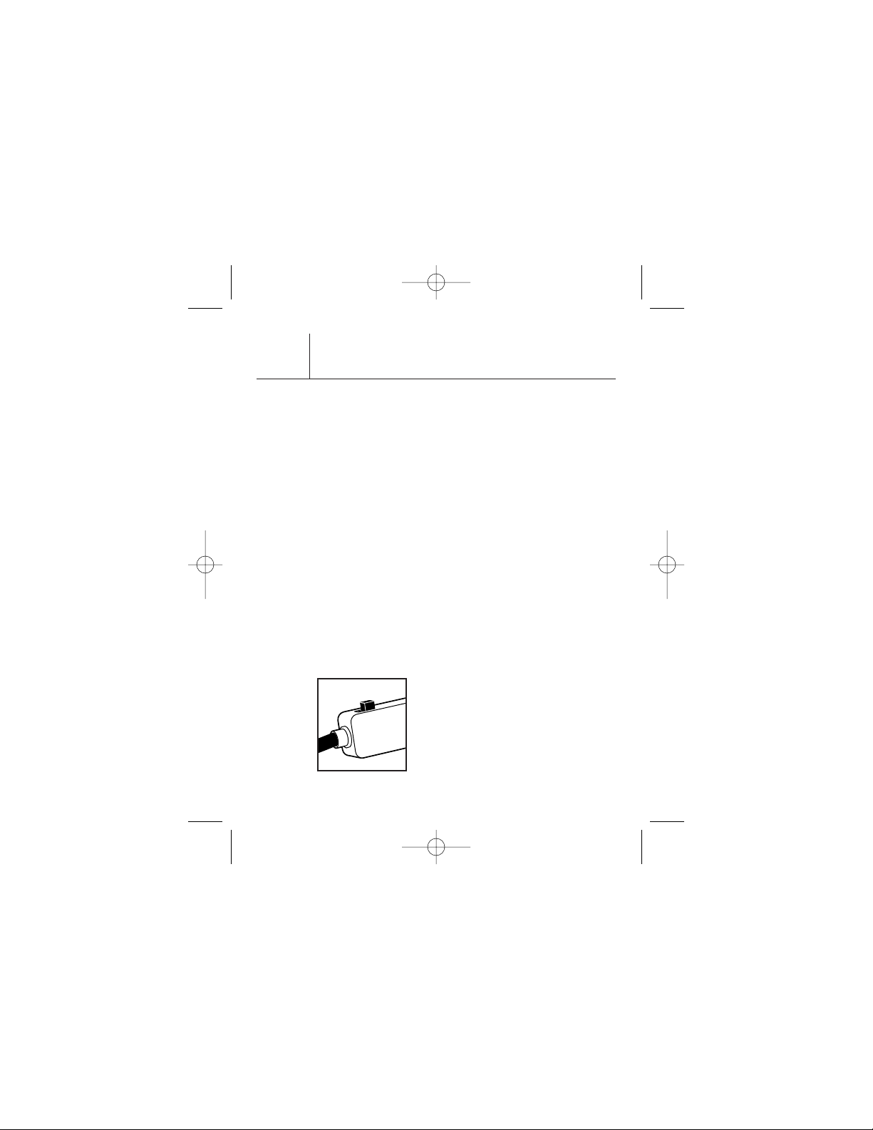
Gain Control Switch:
The gain control switch located on the supplied power
injector is used to control the amplification of the
antenna. Distant stations may need amplification.
See Fig. 3.
FM-50
Fig. 3
OFF/ON
TO
RECIVER
6
“ON” for Amp
Fig. 3
T0100-FMPRO-OM.qxp 3/26/03 12:45 PM Page C7
Page 8

Limited Warranty
TERK is a registered trademark. The TERK logo is a trademark of the TERK Technologies Corp.
TERK TECHNOLOGIES CORP. (TERK) warrants this product against defects in
materials or workmanship for one year from the date of purchase. During this
warranty period, this product will be repaired or replaced, at TERK’s option,
without charge.
Please read your instructions thoroughly and use this product only as directed.
This warranty does not cover any damage due to commercial use, accident,
misuse, abuse, or negligence. This warranty is valid only in the United States
of America.
Repair or replacement as provided under this warranty is the exclusive remedy
of the consumer. TERK shall not be liable for any incidental or consequential
damages for breach of any expressed or implied warranty on this product,
except to the extent prohibited by applicable law. Any implied warranty of
merchantability or fitness for a particular purpose on this product is limited to
the duration of this warranty.
For more information, visit www.terk.com. or,
for technical support, call 1.800.942.TERK (8375).
71P010
T0100-FMPRO-OM.qxp 3/26/03 12:45 PM Page C4
 Loading...