

Page 1

Installation Manual
Page 2

- 2 -
Warning and Safety Information
FCC Information
This device complies with FCC Rules Part 15 Operation and is subject to the following two conditions:
(1) This device may not cause harmful interference and
(2) This device must accept any interference that may be received, including interference that may
cause undesired operation.
NOTE:
The manufacturer is not responsible for any radio or TV interference caused by unauthorized
modifications to this equipment. Such modifications could void the user’s authority to operate the
equipment.
Important Notice
It is unlawful in most states for a person to drive a motor vehicle which is equipped with a television
viewer or screen that is located in the motor vehicle at any point forward of the back of the driver’s
seat, or that is visible, directly or indirectly, to the driver while operating the vehicle. In the interest of
safety, this device should never be installed or operated where its video content will be visible, directly
or indirectly, by the operator of the motor vehicle.
Page 3

- 3 -
Copyrights and Trademarks
© 2009 Audiovox Corporation. All rights reserved.
FLO, FLO TV and the FLO TV logo are trademarks of QUALCOMM Incorporated.
QUALCOMM is a registered trademark of QUALCOMM Incorporated in the United States and may be
registered in other countries.
AUDIOVOX is a registered trademark of Audiovox Corporation.
ADVENT is a registered trademark of Audiovox Corporation.
Technical Information
The
FLO TV
service operates on UHF channel 55 (720 MHz) and is multicast from terrestrial towers.
Coverage will vary and reception is dependent upon the FLO TV module in your vehicle being within
range of the towers. Coverage area can be viewed on the FLO TV web site (www.flotv.com).
The FLO (Forward Link Only) TV service is transmitted over the
FLO TV
network and received by the FLO
TV module in your vehicle. Along with the television program material, data is transmitted for the
program guide and is updated on a regular basis. If you are out of the coverage area the program
guide will be updated when the vehicle returns to the coverage area.
Page 4

- 4 -
Safety Precautions
Installation of the FLO TV product requires careful planning and preparation. Be extremely careful of
the airbags in vehicles and not to have any FLO TV component or wire harness interfere with them.
Keep wiring away from any air bag wiring (usually identified by yellow connectors and yellow wire
jackets). Damage to air bag wiring can result in personal injury to vehicle occupants.
When connecting power and ground in a vehicle, insure that the ACC wire is fused at the point where it
is connected to the vehicle ACC wiring. Failure to do so can result in damage to the vehicle if a short
circuit develops between the vehicle connection point and the FLO TV product.
Do not install any FLO TV component (e.g. wired remote control) where it may obstruct the driver’s
view through the windshield, or any of the vehicle’s indicator displays.
Page 5
- 5 -
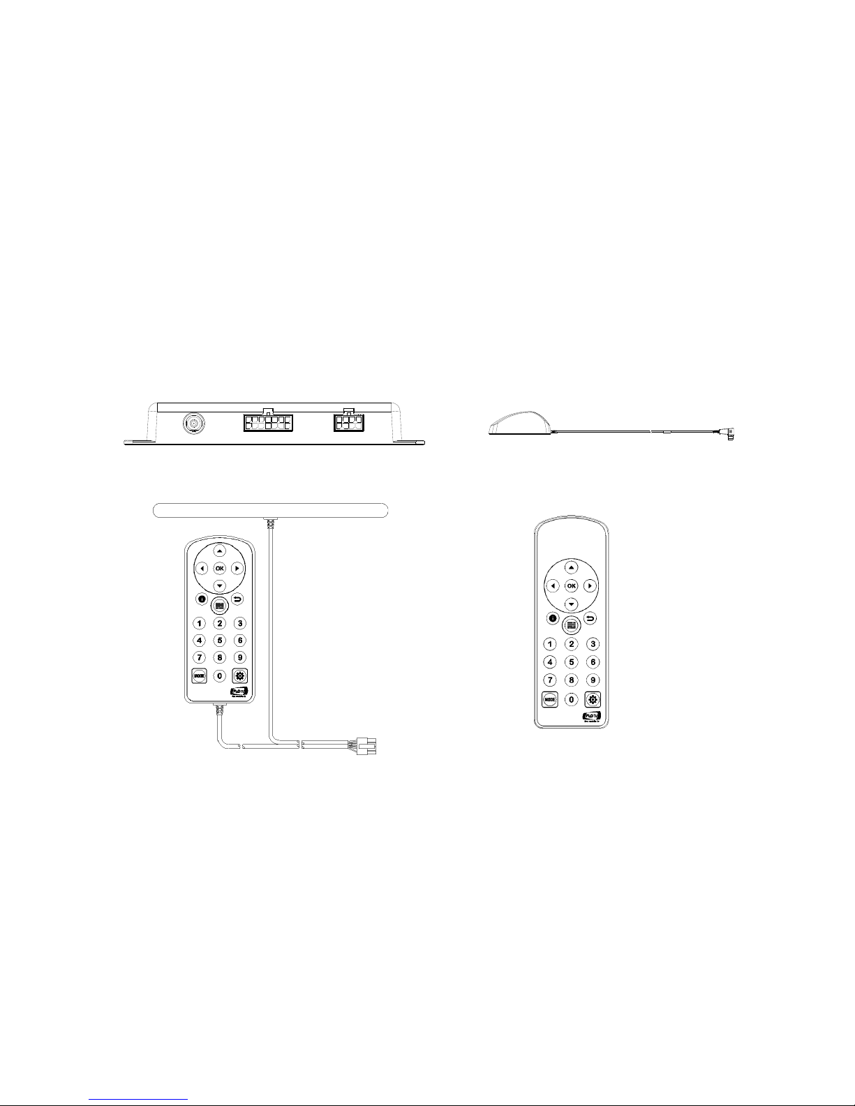
FLO TV Kit Contents
The following items are included with your purchase of the FLO TV kit.
FLO TV Module FLO TV Antenna
Wired Remote Control with Antenna Wireless RF Remote Control
Page 6
- 6 -
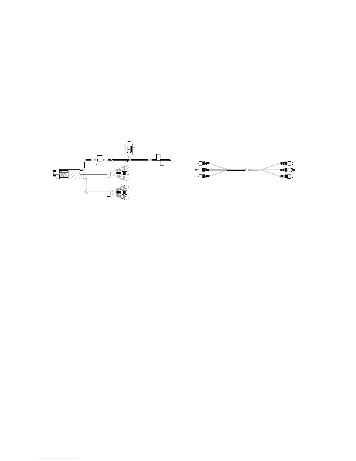
Main Wire Harness RCA Male to Male Harness
NOTE:
The FLO TV kit also includes an antenna tail, antenna tape pad, owner’s manual, this
installation manual, and a hardware kit that includes four wire ties.
B
Page 7
- 7 -
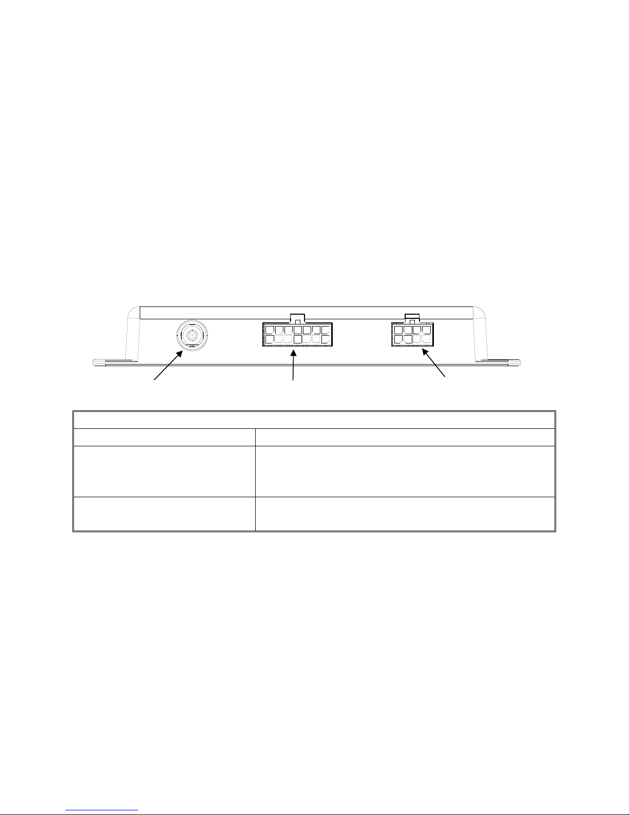
Connectors and Controls
The illustration below details the FLO TV Module connectors for quick reference.
FLO TV Module Connectors
FLO TV Antenna Connector Antenna connection for the FLO TV antenna
Main Wire Harness Connector 14 Pin connector which provides input power to the
FLO TV Module along with Audio and Video Input and
Output.
Wired Remote Control
Connector
8 Pin connector for the connection of the Wired
Remote Control.
FLO TV Antenna Connector
Wired Remote Control Connector
Main Wire Harness Connector
Page 8

- 8 -
Vehicle Preparation
1. Read the manuals to become familiar with the electrical requirements and connections of the
FLO TV kit.
2. Prepare the vehicle by removing any interior trim necessary to gain access to the vehicle’s
wiring as well as areas where the interconnecting wire harnesses will be located.
3. Locate an accessory power source (+12VDC present when the ignition key is in the accessory or
run positions. 0VDC should be present when the ignition key is in the OFF position), and a good
ground location. Generally, these wires can be located at the ignition switch or fuse box.
NOTE:
Ensure that the fuse on the wire harness remains intact during the installation and is
connected directly to the accessory power source. Removal of the fuse may result in
vehicle wiring damage.
4. Run the wire harnesses throughout the vehicle as required. (Examples of suggested wiring
configurations are detailed on the following pages.)
5. Be sure that all wiring is protected from sharp edges and is routed in such a manner that it will
not be pinched when fully installed.
6. Be sure to leave enough slack in the wiring at each component to allow for sufficient working
room.
Page 9
- 9 -
B
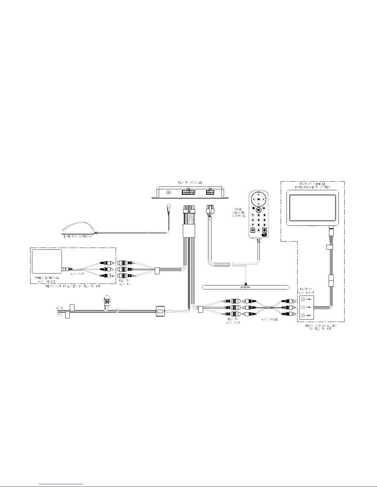
Wiring Diagrams
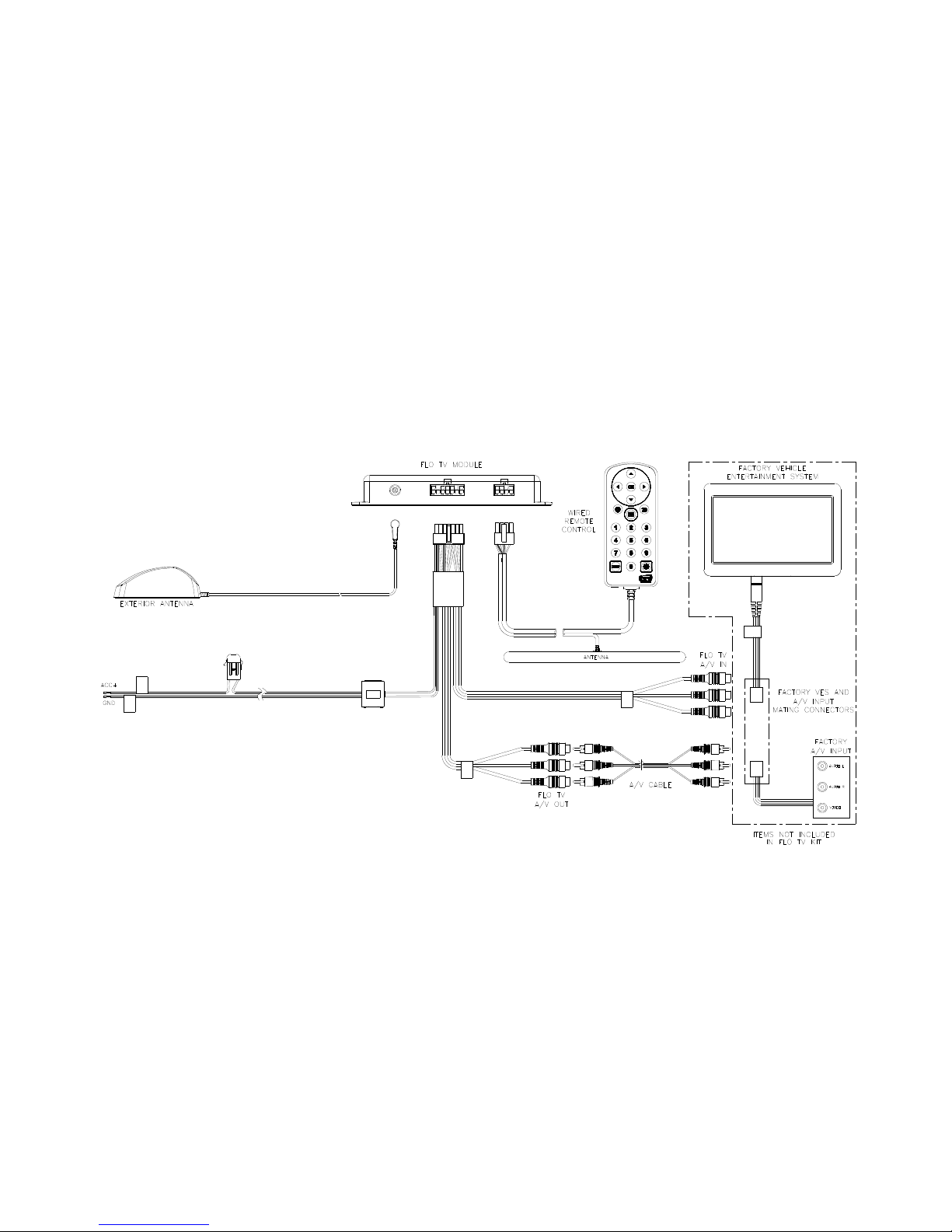
An overview of the FLO TV kit wiring diagram for connection to a Factory Vehicle Entertainment System
(VES) is shown in Figure 1 below.
Figure 1 – FLO TV Wiring Diagram with Factory VES & A/V Input
Page 10
- 10 -
B
To connect the FLO TV kit to a Factory Vehicle Entertainment System (VES), via the connectors
between the Factory VES and A/V input, follow the diagram shown in Figure 2. This installation is
possible if mating connectors between the Factory VES and Factory A/V input are available.
Figure 2 – FLO TV Wiring Diagram with Mating Connector Input
Page 11
- 11 -
B
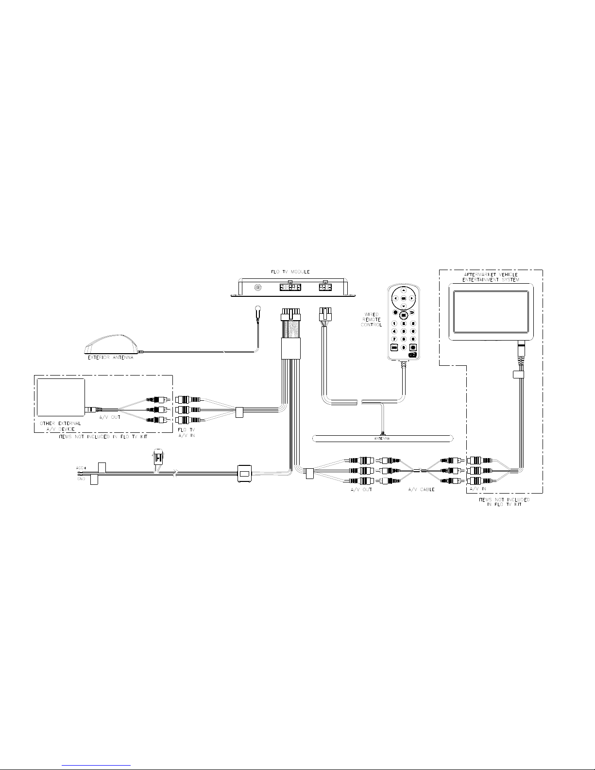
An overview of the FLO TV kit wiring diagram for connection to an aftermarket Vehicle Entertainment
System (VES) is shown in Figure 3 below.
Figure 3 – FLO TV Wiring Diagram with Aftermarket VES
Page 12

- 12 -
FLO TV Module Installation
Choose a mounting location for the FLO TV Module which is convenient, such as under a seat, under or
behind the dashboard, or in the trunk, etc. The location should be one where the FLO TV Module will
not get damaged or kicked and where the wiring can be easily hidden. The FLO TV Module should not
be located where it will be in direct sunshine. The FLO TV Module has four mounting holes for
securing the FLO TV Module to the vehicle by use of the included wire ties or by other means. If screws
are used to mount the FLO TV Module, do not over tighten as the plastic case may be damaged.
FLO TV Antenna Installation
The FLO TV Antenna incorporates a magnet, which is designed to hold the antenna in place on the
exterior of the vehicle, and allows for a semi-permanent antenna installation. The FLO TV kit also
includes a double sided adhesive tape pad, which is recommended to be affixed to the bottom of the
FLO TV Antenna for a permanent antenna installation.
Page 13

- 13 -
Mounting the FLO TV Antenna on the Vehicle
Mounting options for the FLO TV Antenna will vary depending upon the vehicle. These instructions are
meant to be a guide. The following steps detail the recommended permanent installation of the FLO TV
Antenna utilizing the antenna magnet and double sided adhesive tape pad.
1. The antenna needs to be mounted on the exterior of the vehicle’s roof for optimal performance.
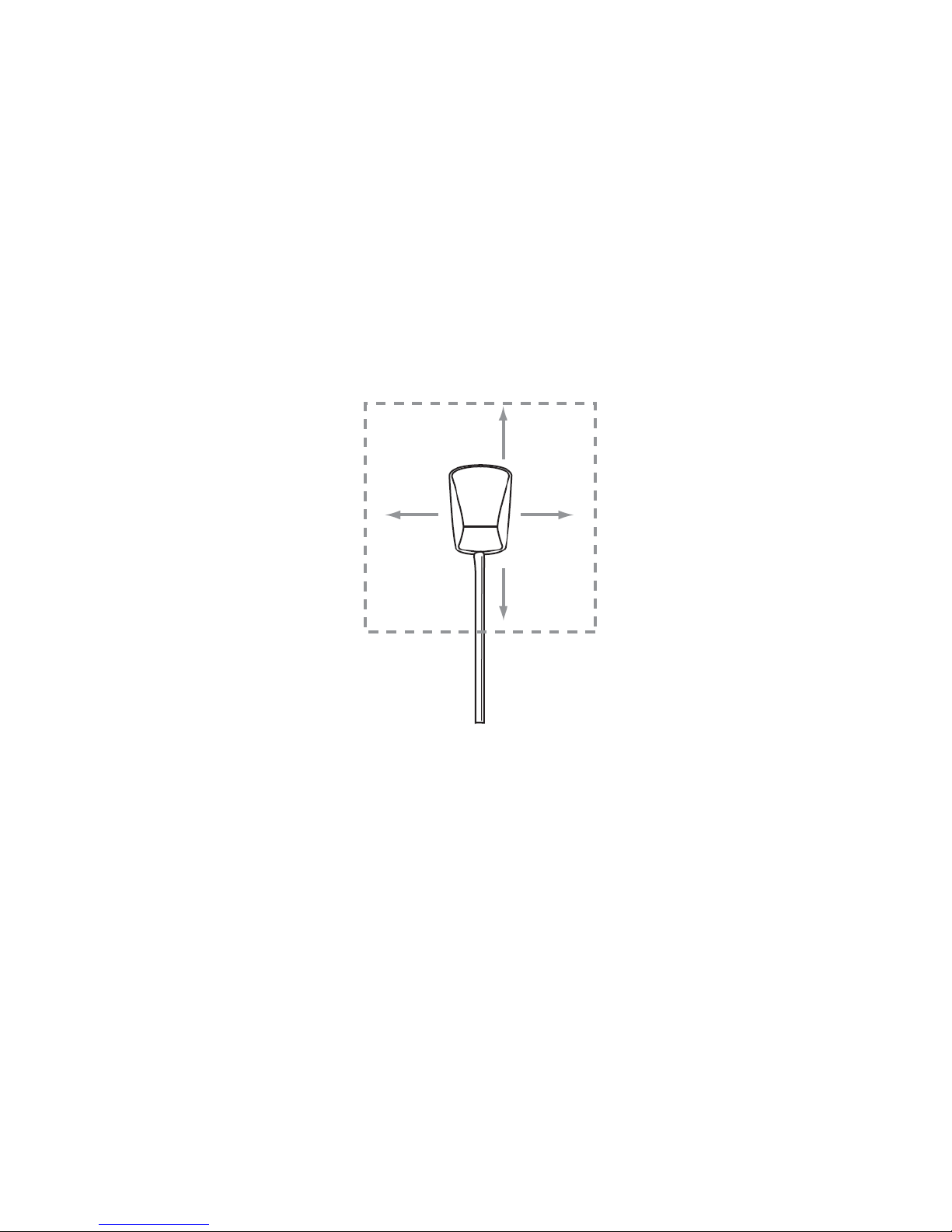
2. Select an appropriate mounting position for the FLO TV antenna. The antenna should be
mounted where no obstructions will block the antenna from receiving the FLO TV signal. The
antenna requires an unobstructed area of 4 inches by 4 inches. Roof racks, roof cargo
containers, another antenna, etc., may obstruct the antenna and cause undesired system
operations. If the vehicle has a potential obstruction, mount the FLO TV Antenna at least 4
inches away from the potential obstruction (but no closer than 4 inches from the roof edge).
(See Figure 4, FLO TV Antenna Placement)
Page 14
- 14 -
Figure 4 – FLO TV Antenna Placement
4”
4
”
4
”
4
”
Page 15
- 15 -
3. Remove the plastic liner from one side of the adhesive backing on the tape pad.
4. Use the four circular cutouts, on the tape pad, for alignment to the four rubber feet on the
bottom of the FLO TV Antenna. Ensure that the tape pad is completely adhered to the bottom of
the FLO TV Antenna.
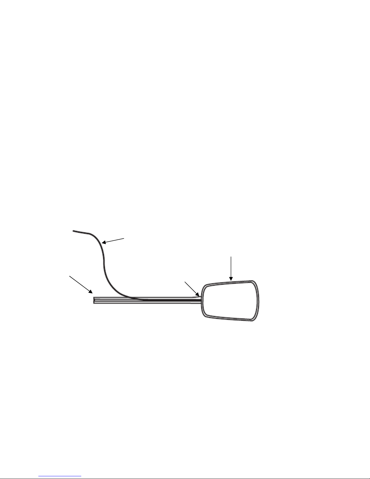
5. Starting at the strain relief on the FLO TV Antenna, attach the antenna tail to the FLO TV
Antenna. Press the antenna cable into the wire track in the antenna tail. (See Figure 5, FLO TV
Antenna Tail Installation)
Figure 5 – FLO TV Antenna Tail Installation
Antenna Tail
Antenna Cable
Strain Relief
FLO TV Antenna
(Bottom View Shown
)
Page 16

- 16 -
6. Clean the surface area of the vehicle where the FLO TV Antenna and antenna tail will be
installed. Ensure that the vehicle surface is clean and clear of any dirt or debris.
7. Remove the plastic liner from the adhesive backing on the bottom of the FLO TV Antenna.
Remove the two plastic liners from the adhesive backings on the antenna tail.
8. Place the FLO TV Antenna and antenna tail on the vehicle roof. The double sided tape and
magnet will secure the antenna and antenna tail in the desired location. (See Figure 6, FLO TV
Antenna Final Installation)
Figure 6 – FLO TV Antenna Final Installation
9. Verify that the installation location of the FLO TV Antenna and antenna tail are correct. Firmly
press the FLO TV Antenna and antenna tail down for approximately one minute to ensure
complete tape adhesion. Allow a 72 hour period for the adhesive tape to cure completely, avoid
car washes during this period.
Page 17

- 17 -
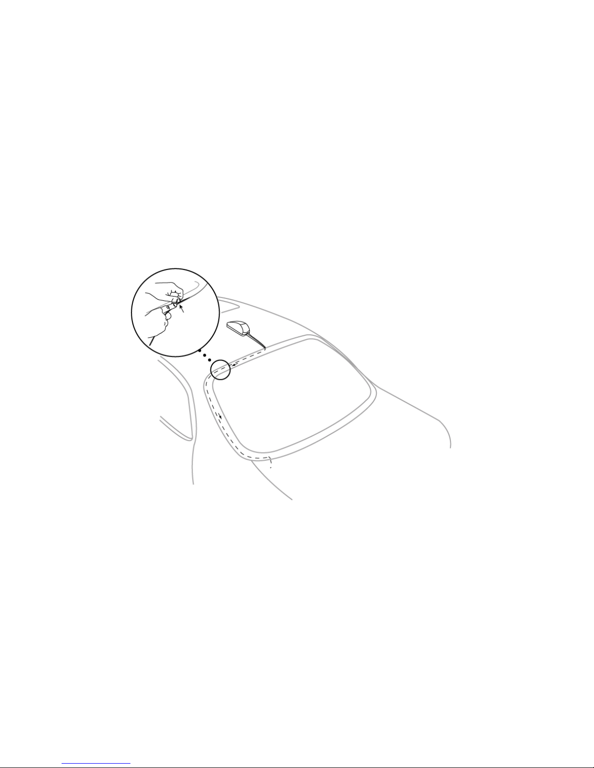
Routing the Antenna Cable
When the antenna has been mounted on the vehicle, the antenna harness can be routed to the FLO TV
Module.
1. Route the antenna cable from the antenna mounting position to the interior of the vehicle,
working the cable under the rear window molding. (See Figure 7, Routing the Antenna Cable)
2. At the lowest point of the rear window, route the cable into the trunk, taking advantage of the
existing cable conduits. Route the antenna harness from the trunk to the passenger
compartment and then to the FLO TV Module Antenna connector.
3. In SUV’s, Minivans, etc., route the cable into the vehicle under the rubber molding of the hatch
door or rear tailgate, and then under the interior trim.
4. Avoid exposing the cable in the driver and passenger areas where it could become entangled in
feet or other objects.
5. Plug the antenna cable plug into the FLO TV Antenna connector on the FLO TV Module. The
antenna plug will snap onto the connector when it is fully seated on the antenna connector.
NOTE:
The exact routing of the antenna cable may vary depending upon where the FLO TV Module will
be installed. Avoid interfering with side curtain airbag locations on the front and back pillars
and above doors.
Page 18
- 18 -
Figure 7 – Routing the Antenna Cable
Page 19

- 19 -
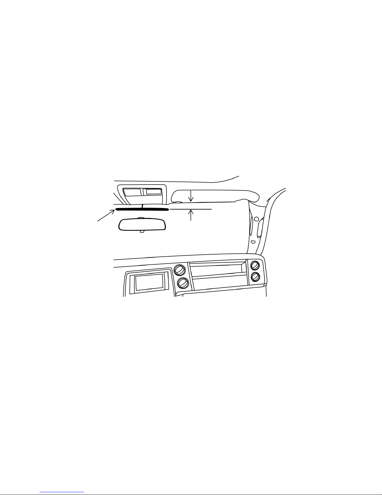
Wired Remote Control Installation
The wired remote control should be installed in the front seating area of the vehicle, where it can be
easily accessed, but not positioned where it could distract the driver or obstruct the driver’s view. It
should also not be located where the wired remote control or its harness could interfere with the
operation of the airbags in the vehicle. It is recommended that the wired remote control is installed in
the vehicle’s center console or glove box and the attached antenna installed on the windshield, two
inches below the top edge of the glass. The antenna should not obstruct the driver’s view (see figure
8)
The wired remote control is intended for use in the event that the wireless remote control is lost or if
the batteries are dead. The wired remote can also be used to change channels from the front
passenger compartment for front seat listening of FLO TV content.
1. With the desired installation location of the wired remote control chosen, route the wire harness
to the FLO TV Module installation location.
2. Route the antenna to the windshield, following the A pillar and tucking the wire into the
headliner. Locate the antenna 2 inches below the top of the windshield (see figure 8), remove
the adhesive backing and press the antenna to the windshield.
3. Connect the 8 pin connector on the remote control to the 8 pin connector on the FLO TV
Module.
Page 20
- 20 -
Figure 8 – Remote antenna placement
2.0 “
Antenna
Page 21

- 21 -
Input Power Connection
The main harness for the FLO TV Module contains a filter box for the 12V ACC line connection. The
main harness also has an in-line fuse for the ACC connection.
1. Connect the ACC input wire to an ignition switch input power line or a switched accessory
power line. The ACC input wire is indicated by the harness jacket color red and the “ACC”
flag on the wire.
2. Connect the Ground input wire to a vehicle ground line. The Ground input wire is indicated
by the harness jacket color black and the “GND” flag on the wire.
3. Ensure that the ACC line is not connected to battery power as this will drain the vehicle
battery. Test the ACC line to validate that the line goes to 0 volts when the vehicle is shut
off.
4. Route the input power leads to the FLO TV Module installation location.
5. Connect the 14 pin Main Harness Connector to the 14 pin connector on the FLO TV Module.
Page 22

- 22 -
Audio & Video Output Cable
To connect FLO TV to a Factory VES via the Factory A/V Input:
The Audio/Video Output connectors on the Main Harness provide the audio and video output from the
FLO TV Module, which must be connected to the vehicle’s factory VES. Refer to Figure 1, herein, for an
overview of the wiring diagram.
1. Locate the factory VES Audio/Video Input jacks. Refer to the vehicle owner’s manual for the
detailed location of the Audio/Video Input jacks. See Figure 1 for reference.
2. For a clean installation, optional right angle RCA Connectors can be used (available from
Radio Shack, Catalog Number 274-915, quantity 3 needed or similar).
3. Connect the optional right angle Audio/Video jacks to one end of the RCA Male to Male
Harness. Connect the right angle Audio/Video jacks to the factory VES A/V Input jacks. (See
Figures 9 and 10 below for examples of the FLO TV A/V Output connections to the Factory
A/V Input or Factory VES A/V Input)
Page 23

- 23 -
Figure 9
Connecting to Factory A/V Input
(Satellite Location)
Figure 10
Connecting Factory VES A/V Input
(Monitor Location)
4. Route the RCA Male to Male Harness from the VES Audio/Video Input jack location to the
FLO TV Module installation location.
5. Connect the RCA Male to Male Harness to the Audio and Video Outputs on the FLO TV
Module Main Harness.
Optional right angle RCA Connectors
Optional right angle RCA Connectors
Page 24

- 24 -
To connect FLO TV to a Factory VES via Hardwired Integration:
If mating connectors are available for the connectors between the Factory VES and the Factory A/V
Input, as indicated in Figure 2, the FLO TV A/V Input and Output can be connected there. This allows
the end user to maintain the use of the Factory A/V Input.
1. Locate the connectors between the Factory VES and the Factory A/V Input and verify if
mating connectors are available.
2. Connect the RCA Male to Male Harness to the FLO TV A/V Output connectors on the Main
Harness. Route the RCA Male to Male Harness to the Factory VES mating connector location.
3. Connect the RCA Male to Male Harness to the Factory VES mating connector as required.
4. Connect the FLO TV A/V Input to the Factory A/V Input mating connector as required.
To connect FLO TV to an aftermarket installed VES:
The Audio/Video Output connectors on the Main Harness provide the audio and video output from the
FLO TV Module, which must be connected to the vehicle’s aftermarket VES. Refer to Figure 3, herein,
for an overview of the wiring diagram.
1. Locate the aftermarket VES Audio/Video Input jacks.
2. Connect one end of the RCA Male to Male Harness to the Audio and Video Outputs on the
FLO TV Module Main Harness.
Page 25

- 25 -
3. Route the RCA Male to Male Harness from the FLO TV Module installation location to the
Audio Video Input location of the aftermarket VES.
4. Connect the other end of the RCA Male to Male Harness to the Audio and Video Inputs of
the aftermarket VES.
Audio & Video Input Connectors
The main wire harness contains RCA Audio/Video Input connectors. Another A/V source can be
connected to this input. The FLO TV Module has an audio/video multiplexer (MUX) that switches the
A/V output between the
FLO TV
service and the A/V input to allow for more system flexibility. The
MODE button on the remote control is used to switch between FLO TV and auxiliary input.
Page 26

- 26 -
Quick Operations Guide
1. Turn the vehicle ignition key to the ON position. Turn on your Vehicle Entertainment System
(VES) and select the source input to which the
FLO TV
service is connected. (Note: Watching the
FLO TV
service for an extended period of time with the engine OFF will run down the vehicle’s
battery.)
2. The VES screen will show the FLO TV splash screen and then the FLO TV preview channel.
3. If you are not subscribed, subscribe to the
FLO TV
service by calling 888-99-FLOTV or by going
on line to www.flotv.com
. The Device ID and Authorization Code of the FLO TV module are
required for subscription. Press the
(Settings) key on the remote to access the Settings Menu.
Press the (down arrow) key to highlight Subscription Information and press the
(OK) key
on the remote. Your Device ID and Authorization Code will be displayed on the VES screen.
4. Once subscribed to FLO TV, press the
(Guide) key on the remote to access the FLO TV
Channel Guide.
5. Press the (up arrow) or (down arrow) key on the remote to change channels.
6. The arrow keys on the remote allow for navigation through the Channel Guide.
7. Press the
(OK) key on the remote to select a desired channel/show from the Channel Guide.
8. Press the
(Information) key on the remote to display the program information related to the
current program.
Page 27

- 27 -
9. Press the
(Settings) key on the remote to access the FLO TV user settings menu (e.g. Parental
Control, etc.).
10. The
(Mode) key on the remote allows the user to switch between the
FLO TV
service and an
auxiliary A/V source if one is connected.
11. Visit www.flotv.com
for more info.
Technical Assistance
For Technical Assistance, please call (800) 225-6074.
Page 28

- 28 -
Troubleshooting Guide
Problem Root Cause Solution
The in-line fuse on the main
harness may be blown.
Check for a bad fuse.
The main harness is not
properly connected.
Verify that the main harness is properly
connected to the FLO Module.
FLO Module does not power on
Input power leads are not
properly connected.
Verify that the input power leads are properly
connected to 12V ACC and Ground.
No Antenna is displayed Antenna is not connected Verify that the antenna connector is connected to
the FLO Module.
No Antenna is displayed Antenna Wire is broken Verify that the antenna wire is not broken.
Acquiring Signal is displayed FLO TV Signal is not being
received.
The FLO TV Antenna is obstructed or the vehicle
is out of the coverage area.
Poor or No Audio RCA Audio Wires are not
connected
Verify that the RCA Audio wires are properly
connected to the main harness Audio Outputs.
Page 29

- 29 -
Troubleshooting Guide (Cont)
Problem Root Cause Solution
Poor or No Audio RCA Audio Wires are not
connected
Verify that the RCA Audio wires are properly
connected to the Audio Inputs on the vehicle’s
rear seat entertainment system.
RCA Video Wires are not
connected
Verify that the RCA Video wire is properly
connected to the main harness Video Output.
RCA Video Wires are not
connected
Verify that the RCA Video wire is properly
connected to the Video Input on the vehicle’s rear
seat entertainment system.
FLO TV Output not selected Press the MODE button on the wired or wireless
remote control to provide FLO TV to the vehicle’s
rear seat entertainment system.
Poor or No Video
Vehicle’s Rear Seat
Entertainment System Video
Input not selected
Change the source inputs on the vehicle’s rear
seat entertainment system until the FLO TV signal
is displayed.
Page 30

- 30 -
Troubleshooting Guide (Cont)
Problem Root Cause Solution
Wired Remote Control does not
work
Wired Remote Control not
Connected
Verify that the Wired Remote Control connector is
connected to the FLO Module.
Batteries installed incorrectly Verify that the two AAA batteries are installed
properly per the polarity markings.
Wireless Remote Control does not
work
Batteries are dead. Replace the two AAA batteries.
Page 31

- 31 -
Page 32

- 32 -
128-8593A
Copyright © 2010 Audiovox Corporation 1.26.2010
Page 33

Quick Start Guide
Page 34

Please refer to the following quick start guide as an
overview to use the
FLO TV
™ service:
1. Turn the vehicle ignition key to the ON
position. Turn on your Vehicle Entertainment
System (VES) and select the source input to
which the
Watching the
FLO TV
FLO TV
service is connected. (Note:
service for an extended
period of time with the engine OFF will run
down the vehicle’s battery.)
2. The VES screen will show the FLO TV splash
screen and then the FLO TV preview channel.
3. If you are not subscribed, subscribe to the
TV
service by calling 888-99-FLOTV or by
going online to www.flotv.com
. The Device ID
and Authorization Code of the FLO TV module
are required for subscription. Press the
(Settings) key on the remote to access the
Settings Menu. Press the (down arrow) key to
highlight Subscription Information and press
the
(OK) key on the remote. Your Device ID
FLO
Page 35

and Authorization Code will be displayed on
the VES screen.
4. Once subscribed to the
the
(Guide) key on the remote to access the
FLO TV
service, press
FLO TV Channel Guide.
5. Press the (up arrow) or (down arrow) key
on the remote to change channels.
6. The arrow keys on the remote allow for
navigation through the Channel Guide.
7. Press the
(OK) key on the remote to select a
desired channel/show from the Channel Guide.
8. Press the
(Information) key on the remote to
display the program information related to the
current program.
9. Press the
(Settings) key on the remote to
access the FLO TV user settings menu (e.g.
Parental Control, etc.).
10. The
user to switch between the
(Mode) key on the remote allows the
FLO TV
an auxiliary A/V source if one is connected.
11. Visit www.flotv.com for more info.
service and
Page 36

Copyright © 2010 Audiovox Corporation
1.26.2010 128-8714A
Page 37

Page 38

Congratulations
Congratulations on your purchase of this Audiovox
product which allows you to use the
FLO TV
™ service.
2
Page 39

Table of Contents
Page
Warning and Safety Information 4
FCC Information 4
Important Notice 4
Copyrights and Trademarks 5
Technical Information 5
Activation/Subscription Information 6
FLO TV Introduction 7
FLO TV Operation 8
Are You Subscribed? 9
Are You Covered? 10
What’s on my FLO TV? 11
Remote Control Battery Replacement 11
Remote Control Operation 12
Remote Control Functions 13
How is FLO TV Programming Rated? 14
Getting Around in FLO TV 16
FLO TV Program Guide 18
Settings Menu 20
Parental Controls 20
Favorite Channels 24
Subscription Information 26
System Information 27
Legal Information 28
Troubleshooting 29
Customer Care 31
Specifications 32
Notes 33
3
Page 40

Warning and Safety Information
FCC Information
IMPORTANT NOTICE
This device complies with FCC Rules Part 15 Operation and is
subject to the following two conditions:
(1) This device may not cause harmful interference and
(2) This device must accept any interference that may be
received, including interference that may cause undesired
operation.
NOTE: The manufacturer is not responsible for any radio or TV
interference caused by unauthorized modifications to this
equipment. Such modifications could void the user’s authority to
operate the equipment.
It is unlawful in most states for a person to drive a motor vehicle
which is equipped with a television viewer or screen that is
located in the motor vehicle at any point forward of the back of
the driver’s seat, or that is visible, directly or indirectly, to the
driver while operating the vehicle. In the interest of safety, this
device should never be installed or operated where its video
content will be visible, directly or indirectly, by the operator of
the motor vehicle.
4
Page 41

Copyrights and Trademarks
Technical Information
© 2009 Audiovox Corporation. All rights reserved.
FLO, FLO TV and the FLO TV logo are trademarks of QUALCOMM
Incorporated.
QUALCOMM is a registered trademark of QUALCOMM
Incorporated in the United States and may be registered in other
countries.
AUDIOVOX is a registered trademark of Audiovox Corporation.
ADVENT is a registered trademark of Audiovox Corporation.
MACROVISION is a registered trademark of ROVI Corporation.
The
FLO TV
is multicast from terrestrial towers. Coverage will vary and
reception is dependent upon the FLO TV module in your vehicle
being within range of the towers. Coverage area can be viewed
on the FLO TV web site (www.flotv.com
The FLO (Forward Link Only) TV service is transmitted over the
FLO TV
vehicle. Along with the television program material, data is
transmitted for the program guide and is updated on a regular
basis. If you are out of the coverage area the program guide will
be updated when the vehicle returns to the coverage area.
This product incorporates copyright protection technology that is
protected by U.S. patents and other intellectual property rights.
Use of this copyright protection technology must be authorized
by Macrovision, and is intended for home and other limited
™ service operates on UHF channel 55 (720 MHz) and
).
™ network and received by the FLO TV module in your
viewing uses only unless otherwise authorized by Macrovision.
Reverse engineering or disassembly is prohibited.
5
Page 42

Activation/Subscription Information
Your FLO TV module will need to be activated before you can begin
enjoying the
subscribe to the
To activate the FLO TV module, call 1-888-99FLOTV (1-888-993-
5688). You may also activate on line at www.flotv.com
be over the age of 13 to activate your subscription.
You will need the following information before you can activate your
subscription:
1. Activation Instructions Card
2. Device ID Number
3. Authorization Code
4. A valid credit card – AMEX/MC/VISA (have your credit card
information ready when you call) Note: The credit card will be
used to verify your account and will not be charged if service was
included with your product purchase.
5. An active email address
6. Billing information (Home/business address linked to your credit
FLO TV
FLO TV
service. Activation takes place after you
service.
. You must
card)
To locate your Device ID and Authorization Code turn on your Video
Entertainment System (VES) in your vehicle and set the source of the
VES to view FLO TV. Press the
access the Settings Menu. Press the (down arrow) key to highlight
Subscription Information and press the
Your Device ID and Authorization Code will be displayed on the VES
screen. Write these numbers down before calling FLO TV.
The FLO TV module is activated over the air. When you are calling,
your vehicle must be within the coverage area and running. Keep the
vehicle on and powered for about ten minutes after you have
activated the unit with
place. Test your FLO TV to make sure that you are subscribed and all
channels work prior to shutting off the vehicle.
FLO TV
(Settings) key on the remote to
(OK) key on the remote.
Services for the activation to take
6
Page 43

FLO TV Introduction
Please refer to the following as an overview to use the
service:
1. Turn the vehicle ignition key to the ON position. Turn on
your Vehicle Entertainment System (VES) and select the
FLO TV
source input to which the
Watching the
with the engine OFF will run down the vehicle’s battery.)
2. The VES screen will show the FLO TV splash screen and then
the FLO TV preview channel or the last channel that was
being viewed.
3. If you are not subscribed, subscribe to the
calling 888-99-FLOTV or
ID and Authorization Code of the FLO TV module are
required for subscription. Press the
remote to access the Settings Menu. Press the (down
arrow) key to highlight Subscription Information and press
the
Authorization Code will be displayed on the VES screen.
4. Press the (up arrow) or (down arrow) key on the remote
to change channels.
(OK) key on the remote. Your Device ID and
FLO TV
service for an extended period of time
FLO TV
on line at www.flotv.com The Device
service is connected. (Note:
FLO TV
(Settings) key on the
service by
5. Press the
Channel Guide.
6. The arrow keys (d ) on the remote allow for navigation
through the Channel Guide.
7. Press the
channel/show from the Channel Guide.
8. Press the
program information related to the current program.
9. Press the
TV user settings menu (e.g. Parental Control, etc.).
10. The
between the
one is connected.
11. Visit www.flotv.com
(Mode) key on the remote allows the user to switch
(Guide) key on the remote to access the FLO TV
(OK) key on the remote to select a desired
(Information) key on the remote to display the
(Settings) key on the remote to access the FLO
FLO TV
service and an auxiliary A/V source if
for more info.
7
Page 44

FLO TV Operation
You can operate the FLO TV module with either the wireless
(RF) or wired remote control.
Hold the wireless remote 6
to 8 inches from your body
for best operation.
When FLO TV is powered on, the following screen will be
displayed until the receiver tunes to a channel:
Upon power up, the
last viewed channel. If the above screen does not appear
press the (Mode) key on the remote control to switch back
to FLO TV.
FLO TV
service will default back to the
8
Page 45

Are You Subscribed?
In order for you to watch the
subscribed. To verify if you are subscribed to the
service press the (up arrow) or (down arrow) key on the
remote to tune to any channel.
If you are not subscribed to a specific channel, that channel’s
screen will be displayed. (Note: Screen background in this
example has diagonal bars in it)
FLO TV
service you must be
FLO TV
If you are not subscribed to any channels, a screen similar to
the one above will inform you.
Some channels may not be available for viewing if they are
not included in the
subscribed to.
FLO TV
service package you are
9
Page 46

Are You Covered?
FLO TV
areas and travel corridors within the United States. Please
visit the FLO TV web site (www.flotv.com
coverage maps in your area.
If you are travelling in an area that is not covered by the
network or travel out of the areas covered by the
TV
network the following screen will be displayed:
service coverage is available in many metropolitan
) to check the
FLO
FLO TV
Once you have returned to an area covered by the
network, FLO TV programming will resume. If you are
planning a trip, check the FLO TV web site (www.flotv.com
see if your route is within the
FLO TV
10
network coverage area.
FLO TV
) to
Page 47

What’s on my FLO TV?
Remote Control Battery Replacement
Remote Control Battery Installation
Please visit www.flotv.com to get an up to date listing of all
channels and shows available on the
FLO TV
service.
1. Slide the cover off the battery compartment.
2. Insert two AAA batteries into the battery holder. Be
sure to observe the correct polarity.
3. Slide the battery cover into position on the remote
control.
11
Page 48

Remote Control Operation
The FLO TV Module comes
with two remote controls,
one a wireless RF (Radio
Frequency) battery
operated remote and the
other a wired remote
control (which is located in
the glove box or center
console).
The wired remote is used
in the event that the
wireless remote control is
lost, misplaced or the
batteries in the wireless
remote control are dead.
The wireless remote
control is RF (Radio
Frequency) and should be
held 6 to 8 inches from
the body for best range.
Both remotes can be used
to fully operate the
service and are used to
access FLO TV channels,
system settings and
subscription modifications
FLO TV
and changes.
12
Page 49

Remote Control Functions
Symbol Function
1,2,3,4,5,6,7,8,9,0
Use for channel changing
(up/down), navigating
menus, and selecting items
Use to select a channel or
setting
Information key –use to
display program information.
Channel Guide – use to
select the channel guide
Back key – takes the user
back one screen when in the
Menu, Show Information,
Show Description, or Guide.
Path ends at full screen TV
Number keys – use to select
favorite channels and for PIN
entry for parental controls
Settings key– allows the
viewer to toggle on/off the
FLO TV settings menu
Mode key– toggles between
FLO TV and an auxiliary A/V
source (Note: Your system
may not have an auxiliary
source)
13
Page 50

How is FLO TV Programming Rated?
TV Ratings
Audiocast Ratings
Parental controls are built into FLO TV so that you can filter
the program and movie content that can be watched on the
FLO TV
type for TV program material and movie material:
TV-Y
TV-Y7
TV-G
RV-PG
TV-14
TV-MA
Movie ratings information, if provided, is available in the FLO
service. Below is a ratings chart based on content
TV programming guide. Audio content can be restricted as
well based on the chart below:
Clean
Explicit
14
Page 51

Notes
o Unrated content (NR) does not have a rating exposed
in the user interface, and the rating string value will
be blank when this occurs.
o FLO TV blocks or allows unrated programs based on
whether the unrated program is allowed to play with
Parental Controls enabled.
o Specific programs identified as most restrictive must
challenge the user to enter the PIN, even if parental
controls are turned on at the least restrictive level.
o Specific programs identified as least restrictive must
NOT challenge the user to enter the PIN, even if
parental controls are turned on at the most restrictive
setting.
o If the correct PIN is entered, the restrictive content
can be displayed.
15
Page 52

Getting Around in FLO TV
Watching the
information or pop-ups occurring while viewing the
program as shown below:
FLO TV
service limits the channel
If you want to see what channel you are on, press the
(Info) key and the following screen and information will
appear:
16
Page 53

Information displayed:
o Channel Logo
o Program Title
o Program Start Time
o Program End Time
o Program rating
Pressing the (Info) key again will display more information
about the channel being viewed as shown below:
Information displayed:
o Channel Logo
o Program Title
o Program Start Time
o Program End Time
o Program Rating
o Episode Title
o Episode Summary
Pressing the (Info) key will return the viewer to the full
screen.
17
Page 54

FLO TV Program Guide
You can access the FLO TV program guide by pressing the
(Guide) key which displays the program guide:
The FLO TV program guide is a matrix of programs and their
start times, organized by channel. A user can view the guide
and tune to a currently playing program or view program
descriptions for future programs. The following information
generally is displayed:
o FLO TV Logo
o Current Time
o Current Day
o Guide Day
o Guide Time
o Channel Logo
o Program Title
o Parental Block Icon (lock symbol)
o More Icon
18
Page 55

Notes
• Programs that are blocked due to Parental Controls display
the locked icon.
• The channel logo column is not selectable.
• The guide loops vertically when you press the (up arrow)
or (down arrow) key.
• The guide is bounded horizontally by time. The user cannot
navigate into the past or beyond the amount of guide data
available.
• Current program tuned is designated by darker cell color
and vertical right color bar when not in focus.
• Guide Day refers to the day within the guide data the user is
currently viewing.
• Guide Time refers to the time within a particular day of
guide data the user is currently viewing. These values
change as the user scrolls right and left through guide data.
• Current Day and Current Time are independent of Guide
Day and Guide Time.
The More Icon is visible when a show’s length extends
beyond the bounds of the current guide view. They are
visible when going forward in time and going back in time.
19
Page 56

Settings Menu
Parental Controls
Press the (Settings) key to enter the Settings Menu and the
following screen will be displayed:
In the Settings Menu, the first selection is Parental Controls,
which is highlighted in light gray. Press the OK key to access
the parental controls menu. The following screen will be
displayed:
20
Page 57

Use the X (right arrow) key to highlight the parental on/off
control and press OK to enable it or disable it. Once enabled,
press the OK key and you will be prompted to create a PIN
(Personal Identification Number) as shown in the following
screen:
Use the remote control keypad to enter a 4 digit PIN. When
the fourth digit is entered the following screen will appear to
confirm the new PIN.
21
Page 58

Re-enter the same 4 digit PIN to confirm the PIN number.
The following screen will be displayed:
(NOTE: Write the PIN down in a secure location. If it is lost
you will have to call 1-888-99FLOTV to reset the PIN. The
PIN cannot be reset online. Do not share your PIN with the
person whose access to programming is being restricted.)
22
Page 59

Once you have set your PIN, you can now change the ratings
limit on TV, Movies and Audio content. To change the
ratings:
Use the T (down arrow) key to highlight TV Rating, Movie
Rating or Audio Limit or Restricted Channels and press the OK
key on the remote control. The following screen will appear:
Use the X (right arrow) and W (left arrow) key to change the
TV rating. Once you get to the rating you want, press the OK
key to select it. Press the (Back) key to return to TV
viewing.
23
Page 60

Favorite Channels
Up to 10 channels can be programmed into the numeric
keys on the remote. Once they are programmed, pressing
any one of them tunes your FLO TV to the channel that
you have pre-programmed to the number key.
If you have not pre-programmed favorites, when you
press a numeric key, you will be prompted by the info bar
at the bottom of the screen asking you if you want to add
the channel to your favorites:
To program favorite channels press the (Settings) key
to access the settings menu. Use the (down arrow) key
to highlight Favorite Channels and press the OK key.
The following screen will appear which lists each channel
available on the
(down arrow) key to highlight a channel and press a
numeric key to set the highlighted channel to a favorite.
In the example below, the Nickelodeon channel is set to
the number 1 key.
FLO TV
service. Use the (up arrow) or
24
Page 61

Once you are back watching the
press a number key to quickly access your favorite
channels. Up to 10 channels can be programmed with the
numeric keypad (0-9).
FLO TV
service you can
25
Page 62

Subscription Information
In the Settings Menu, use the (up arrow) or (down
arrow) key to highlight Subscription Information and
press the OK key, the following screen will be displayed:
This screen tells you the basic information of your FLO TV
system. (Note: The Authorization Code and Device ID will
be different from the above screen, which is for reference
only.)
26
Page 63

System Information
In the Settings Menu, use the (up arrow) or (down
arrow) key to highlight System Information and press the
OK key, the following screen will be displayed:
This screen tells you the signal strength of the FLO TV
signal. If you are having reception problems, go to this
page to see if the FLO TV signal is available at your
location. (Note: The Device ID will be different from the
above screen, which is for reference only.)
27
Page 64

Legal Information
Use the (down arrow) key to highlight Legal
Information. This information governs the terms and
conditions of your use of the
network. To see the full text and the privacy policy go
TV
to www.flotv.com
.
FLO TV
service and the
FLO
28
Page 65

Troubleshooting
FLO TV Screen Observed Explanation
You are not subscribed and
are not able to access any
channel except the FLO TV
channel.
Unable to access any
channel;
you are out of the coverage
area.
You are either out of the
coverage area or your FLO
TV module has not updated
the program guide
information. The
Service will return to normal
when you are back in the
coverage area.
FLO TV
29
Page 66

Troubleshooting
cont’d)
FLO TV Screen Observed Explanation
(c
You are in a fringe coverage
area; programming will
return to normal when you
are back in the coverage
area.
You are out of the coverage
area; programming will
return to normal when you
are back in the coverage
area.
Contact the car dealer
or the retailer where this
product was installed or
purchased.
30
Page 67

Troubleshooting
(cont’d
Customer Care
Problem Root Cause Solution
Poor or No Video Vehicle’s Rear Seat
Wireless Remote
Control does not
work
(
Entertainment
System Video Input
not selected
Batteries installed
incorrectly
)
Change the source
inputs on the
vehicle’s rear seat
entertainment system
until the FLO TV
signal is displayed.
Verify that the two
AAA batteries are
installed properly per
the polarity markings.
Engine noise
(whine, pops,
static) can be
heard when FLO
TV is in AUX mode
Batteries are dead Replace the two AAA
batteries.
Ground loops in
the system wiring
generate noise
Use only battery
powered devices such
as portable media
players or use ground
isolation products to
eliminate noise.
Call
1-888-99FLOTV (1-888-993-5688)
31
Page 68

Specifications
Power 12 VDC
Current Draw 200 mA Max
Video Output 1 V
75 ohms
p-p
Video Format NTSC
Audio Output 200 mVRMS
32
Page 69

Notes
33
Page 70

Notes
34
Page 71

35
Page 72

 Loading...