

Page 1
"
0
0
.
0
..,c;Hr
0
0
0
LCDl-3
Page 2
~:.~
LCD (LIQUID CRYSTAL DISPLAY) MONITOR
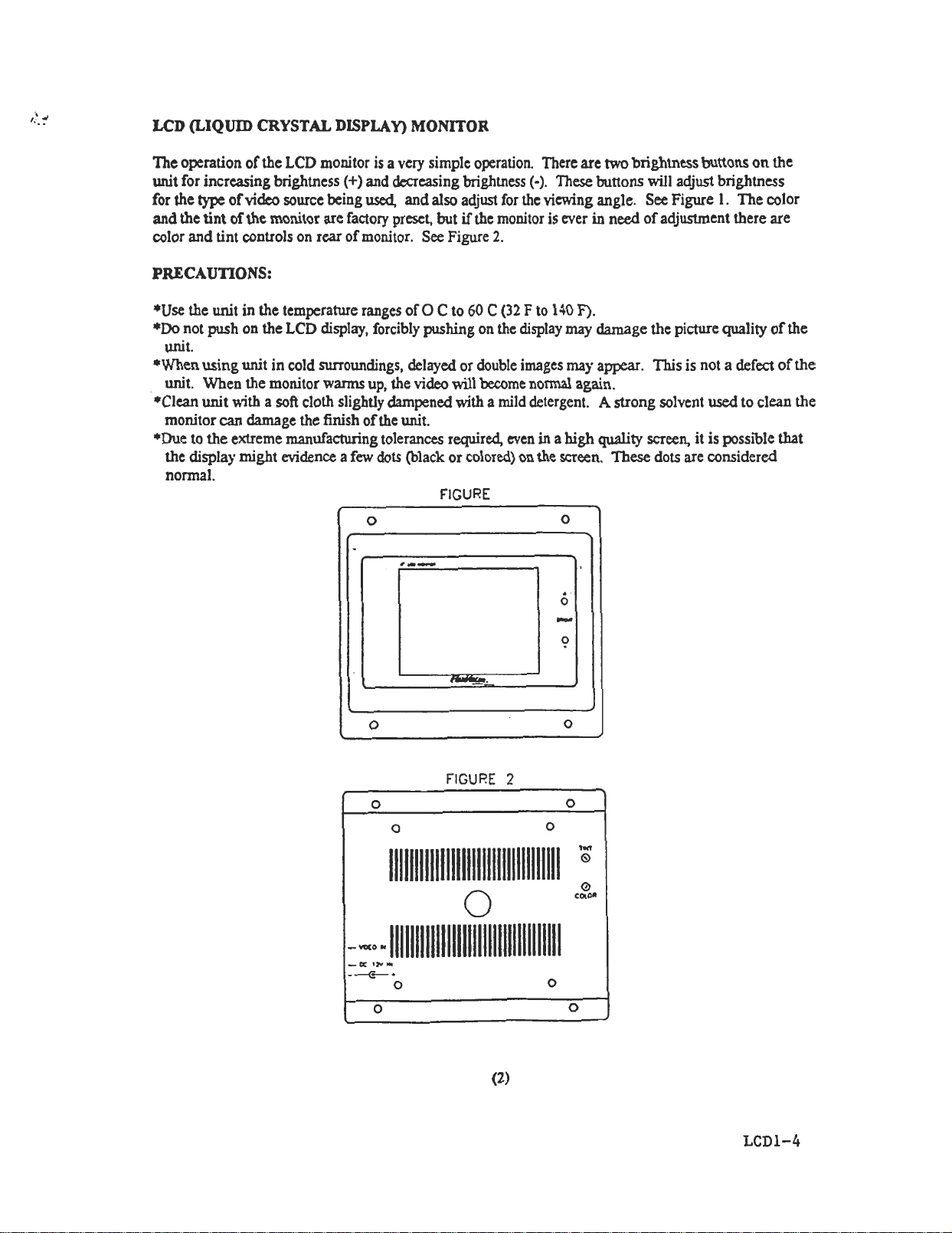
The operation of the LCD monitor is a very simplc operation. There are two brightness buttons on the
unit for increasing brightness (+) and decreasing brightness (-). These buttons MIl adjust brightness
for the type ofvideo source being used, and also adjust for the vicMng angle. See Figure I. The color
and the tint of the monitor are factory preset, but if the monitor is ever in need of adjustment there are
color and tint controls on rear of monitor. See Figure 2.
PRECAUnONS:
*Use the unit in the temperature ranges of O C to 60 C (32 F to 140 F).
*Do not push on the LCD display, forcibly pushing on the display may damage the picture quality of the
unit.
*When using unit in cold surroundings, delayed or double images may appear. This is not a defect of the
unit. When the monitor warms up, the video will become normal again.
*Clean unit with a soft cloth slightly dampened with a mild detergent. A strong solvent used to clean the
monitor can damage the finish of the unit.
*Due to the extreme manufacturing tolerances required, even in a high quality screen, it is IX>ssible that
the display might evidence a few dots {black or colored) on the screen. These dots are considered
normal.
FIGURE
0
0
,.-
6
0
0
FIGURE 2
0
(2)
LCDl-4
Page 3

LCDSELECTORSTATION
Each monitor will have its O\\"D selector station. The station consists of a S-lX>sition rotaJY S\\itch. 1/8"
stereo headphone jack. and a volume control. The rotary SYfitch has five different selections to choose
from (Off, Radio, Video I, Video 2, Video 3). In the "00- position there is no IX>wei to the unit In the
-Radio" position there is audio to the headphone system, but the LCD monitor mIl be off. In the three
different "Video- IX>sitions you will select bern.een what options were chosen for your vehicle. For the
unit to operate all three "Video" ]X>sitions, the \ideo sources (example: Video Cassette Player) must have
power turned on at the units.
Plug in an 118" stereo headphone jack into the headphone jack on the selector station to get your audio.
.The volume control beside the jack will adjust the audio level. In "Radio" mode the radio system \ltill
deliver sound to the selector station. If the audio is not loud enough or too loud. then adjust the volume
control at the radio source for a desired audio Ie\.el to give the volume control the best range of operation.
See Figure 3 belo~..
Note: When turning unit from a "Video" source to the "Radio" source the LCD panel will be lit for a
split-second and then shut-off. This is nonnal operation for the unit.
!- :r .("0 7,
..~v ""
SIGNAL DISTRIBunON BOX
The distribution OOx is the heart of the FlexVision system. This OOx distributes all of the \ideo and audio
signals to the proper monitor. This gives each person using the S)'stem the flexibility to choose ~.hat
they want to do regardless of \\'hat an)-body else in the vehicle is doing. For example: one person could
be watching television, another person playing a vicko game, another watching a video tape, and yet
another listening to the radio. Each distribution box can drive up to four monitors (optional) and selector
stations. Figure 6 shows a basic setup diagram emphasizing the Signal Distribution Box.
(3)
LCDl-5
Page 4

TUNER BOX (TBX-l000) OPTIONAL
The tuner box is a very easy system to operate. To use the tuner box you must first use the LCD selector
station and dial to Video 1,2, or 3 whichever is the correct selection. You can operate the tuner either by
using the Tuner Control Station (Fig. 4), or by using the the supplied,Unified Remot~ Control (Fig. S).
Below is a description of the Tuner Control Station and Remote Control. Notice that many of the features
are identical at either the Tuner Control Station or the Remote Control. The Video Cassette Player
functions on the bottom of the remote operate the Audiovox model A VP-67S0. Note that the TVNideo
button. Mute. Vol. Up/Down, TV/CATV, and the Picture Selector do not fu11y perform their functions
\\ith the LCD S).stem, but those TV functions do fully operate the AVT-97S (9" TV) and the A VT-147S
(13" TV) Audiovox telMsions.
Refer to Figures 4 and S on next page to verify operation.
1. POWER BUTTON -Press this button to turn the tuner on. Press again to turn unit off.
2. AUTOPROGRAM BUTTON -When the AutoPrograrn button is depressed, all channels in TV mode
are searched and tuned, and the channels Vtith signals detected are aut?matica11y stored
3. CHANNEL UP/DOWN BUTrONS -Use these buttons to advance to next higher or next lower
channel.
4. ERASFJWRITE BUTfON -This button is used to manually add or erase any channel into the
memory. If the channel is stored, then simply push the Erase/Write button once to erase the channel.
If the particular channel is erased, then push once to store.
5. SKIP/SEARCH BUTrON -This button selects between Skip and Search Mode. In "Skip mode" the
tuner only stops on channels that are programmed into memory when the Channel Up/Down buttons
are used. When Skip mode is off the tuner M11 stop on all active channels. -
6. DIRECT ACCESS BUTTONS. Use these buttons to make a direct channel selection. The channel
number chosen will be displayed on the screen for a few seconds. The direct access is carried out
mth 0-9 kej"S (0-99ch).
7. TU~R POWER LIGHT -The light will ~ dimly lit when the tuner is off, and light \\ill ~ brighter
Mth JXIWer on.
8. REMOTE SENSOR -When using remote control, JX>int the remote control at the remote sensor on
the tuner control station.
(4)
LCDl-6
~
Page 5

 Loading...