

Page 1

INSTALLATION GUIDE FOR
CELLULAR CAR TELEPHONE
555 Wireless Blvd., Hauppauge, NY 11788
288E9930
Page 2
1
Important
There are some basic rules that apply to most hardware installation procedures
and need to be observed to prevent damage or injury.
1. Always make sure that any power is disconnected to the vehicle before handling any
electrical components like wiring, fuseboxes, connectors, etc.
2. Never force any connection between components, electrical connectors or the like.
3. Always use the proper tools for the task at hand. Using improper tools may cause
damage to yourself, your vehicle, or your cellular telephone system.
4. Think through all the necessary steps of installation before actually beginning the
procedure and equip yourself for all steps to be performed.
5. Always make sure your workspace and your tools are clean and tidy. The
introduction of dirt or grease may hinder the performance of your cellular telephone
and related components.
Installation Procedure
1. Before we begin
You will need the following items in order to properly install the cellular telephone in the
trunk of an automobile.
• Your CMT9300 kit includes the following parts:
1. Cradle (CR93)
2. Mount Bracket (MT93)
3. Power Cable (EPC91)
4. Extension Cable (EIC91)
5. Clamshell (CM5)
6. Screw kit (SK93)
7. HF Microphone (MIC40)
8. Installation Manual (IMCMT9300)
• Your CMT9300 kit does not include the following parts:
9. Stand for Cradle
10. Screw (M5 × 25)
Inst.Guidebody 02.4.3, 11:38 AMPage 1 AdobePageMaker6.5J/PPC
Page 3
2
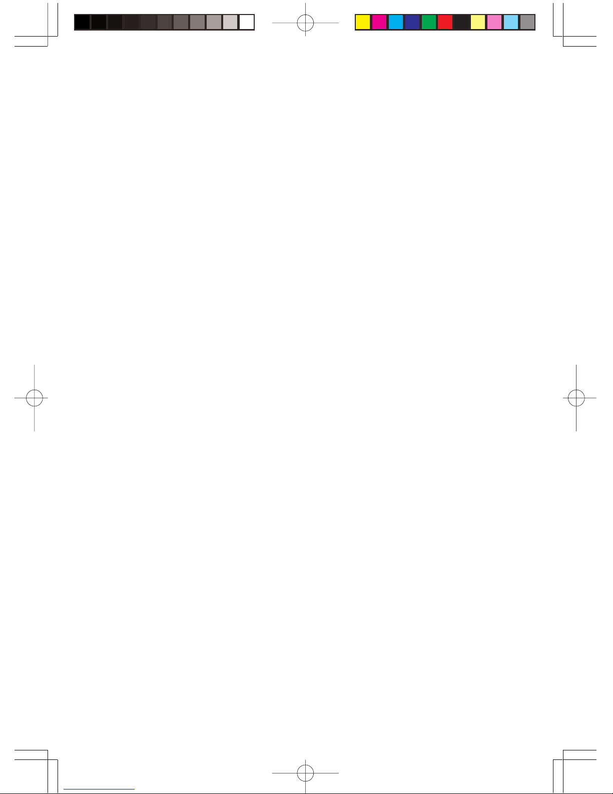
2. Mount the Transceiver unit
To install the cellular telephone with the transceiver unit located in the trunk-space of the
automobile follow the steps outlined below.
a. Place the mounting bracket so that the
four bracket holes line up with the transceiver holes.
b. Replace the four screws (supplied M4 ×
8mm) in the screw kit so that the mounting bracket is secured to the transceiver
unit.
c. Place the unit top-side up (bracket feet
down), utilizing the included flatwashers,
insert the four self-tapping screws (M5 ×
25mm is recommended) and tighten them
down.
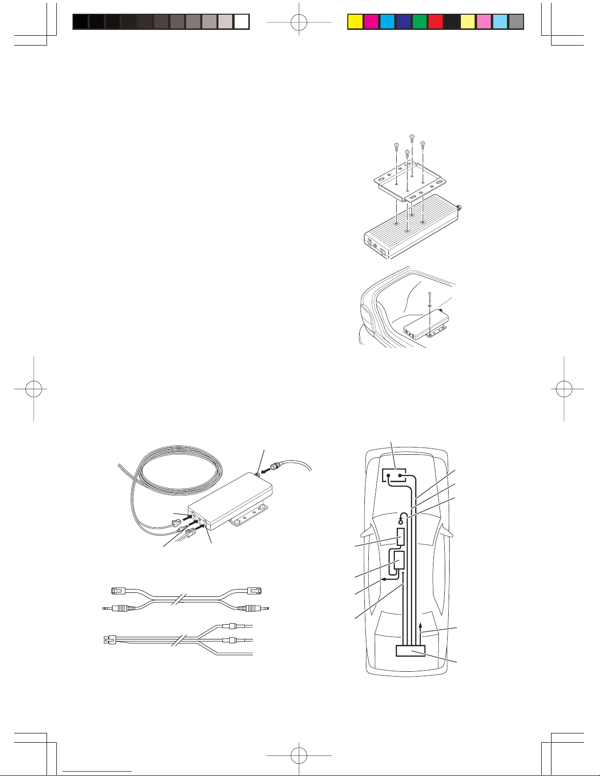
Orange
Extension Cable
Power Cable
fuse 3A
fuse 1A
Red
Black
3. Wiring
a. Connect the cables to the mounted transceiver unit using the supplied trunk mount
extension cable as illustrated.
Car Battery
Ground (Black)
Back up (Red)
Ignition (Orange)
Extension cord
Hands-Free Mic
Cradle
Hand Set
Transceiver unit
Antenna
Antenna Terminal
Power Cable Socket
Microphone Unit Jack
Curly Cord
Socket
Inst.Guidebody 02.4.3, 11:38 AMPage 2 AdobePageMaker6.5J/PPC
Page 4

3
4. Mount the Cradle and Handset
a. Using a pedestal mount. The cradle unit
can be mounted as displayed. Be sure
to use only supplied M4 × 8mm screws.
Using improper screws will damage the
cradle unit.
b. Plug in the handset and Hands-Free
Mic.
c. Check to make sure ALL signal and
power leads are in place and properly
connected.
Hands-Free Mic
Inst.Guidebody 02.4.3, 11:38 AMPage 3 AdobePageMaker6.5J/PPC
Page 5

4
5. Antenna
The following are recommended antenna and cable installation instruction for Transceiver unit. These instructions must be followed in order to comply with the FCC RF
exposure requirements.
• Standard type 1
Antenna type : Glass mount type (“thru–glass” antenna) - Colinear
Mount location : Rear window of a vehicle
Antenna cable : RG-58/U 8 feet (2.44m) or longer
Install the antenna on the upper position of the rear window and centered as shown
in the diagram below.
• Standard type 2
Antenna type : Roof top mount type-1/4λ Mono Pole
Mount location : Roof top of a vehicle
Antenna cable : SUMITOMO 2.4DS-FXL (or 2.4DS-GXLA) 10 feet (3.05m) or
longer
Install the antenna near the roof top rear and centered as shown in the diagram
below.
Rear window
Transceiver unit
Antenna
Coaxial cable
RG-58/U
8 feet or longer
Rear window
Antenna
Transceiver unit
Roof Top
Antenna
Coaxial cable
Antenna
Inst.Guidebody 02.4.3, 1:34 PMPage 4 AdobePageMaker6.5J/PPC
Page 6

5
• Standard type 3
Antenna type : Colinear
Mount location : On the right of trunk lid
Antenna cable : SUMITOMO 2.4DS-GXLA, 2.5DS-GXCA 8.85 feet (2.7m) or
longer
Install the antenna on the right position of the trunk lid as shown in the diagram
below.
• Standard type 4
Antenna type : Roof top mount type-1/4λ Mono type
Mount location : Roof top of a vehicle
Antenna cable : SUMITOMO 2.4DS-GXLA, 2.5DS-GXCA 14.76 feet (4.5m)
or longer
Install the antenna on the left position of the roof top as shown in the diagram
below.
Antenna
Rooftop
Transceiver unit
Antenna
Coaxial cable
Antenna
Rooftop
Transceiver unit
Antenna
Coaxial cable
Rear window
Inst.Guidebody 02.4.8, 10:38 AMPage 5 AdobePageMaker6.5J/PPC
Page 7

6
• Standard type 5
Antenna type : Roof top mount type-1/4λ Mono type
Mount location : Roof top of a vehicle
Antenna cable : SUMITOMO 2.4DS-GXLA, 2.5DS-GXCA, 2.5DS-GXCA
12.30 feet (3.75m) or longer
Install the antenna on the center position of the roof top as shown in the diagram
below.
Antenna
Rooftop
Transceiver unit
Antenna
Coaxial cable
Inst.Guidebody 02.4.8, 10:38 AMPage 6 AdobePageMaker6.5J/PPC
 Loading...