

Page 1
Installation Instructions
ModelCMOS1 Camera (V2.0)
FEATURES:
● High Resolution 1/4'' CMOS Color Camera
● Compact Zinc Alloy Die Cast Body
● Waterproof Housing
●
Waterproof Microphone
● Adjustable Mounting Angle
● W ide Angle Lens
● Selectable Normal or Reverse Image
Page 2
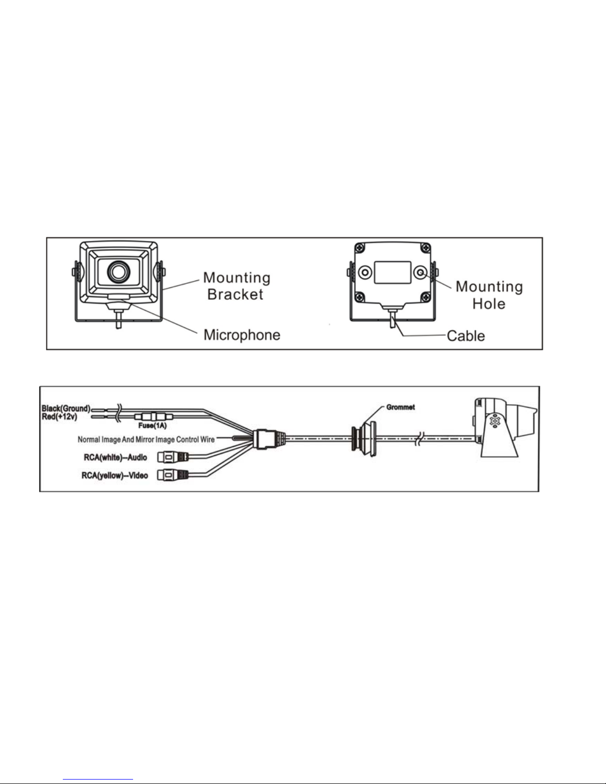
Camera View :
Cable Connector End View:
1
Page 3

2
Specification:
1. Voltage: DC12V
2. Current: 50mA
3. Signal System: NTSC
4. Image sensor: 1/4
'' CMOS Sensor
5. Horizontal Resolution: 480 Lines
6. Viewing Angle: 130 degrees
7. Minimum Illumination: 0.3 Lux
8. Image Display: Normal Image or Reverse Image
''
9. Camera Outer Dimensions: 2.52
'' (w) x 2.15 (H) x 1.73'' (D)
10. Weight: 7 OZ
Normal/Reverse Image Control Wire
The Control Wire is located at the camera cable connector . When the Control Wire is
snipped,the camera image will be normal.When Control Wire is not snipped, the
camera image will be reversed.
Page 4
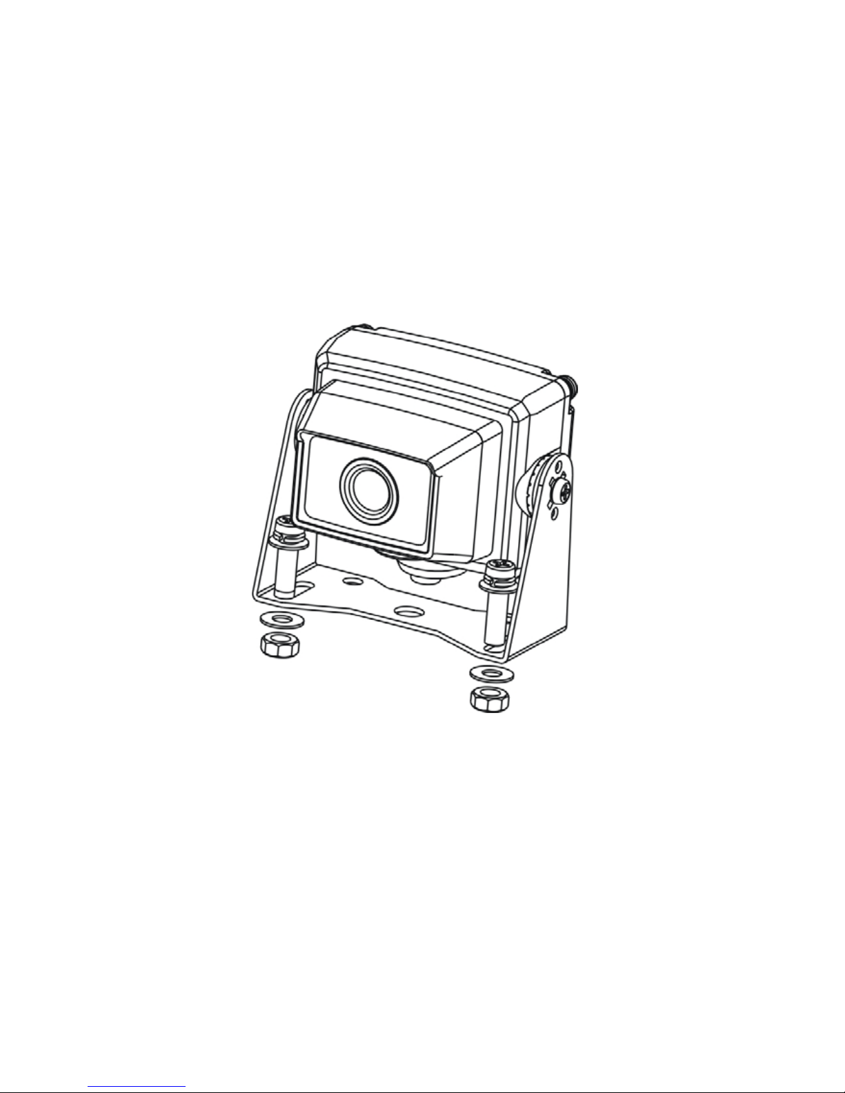
Camera Installation 1 (Viewing angle is adjustable)
3
Page 5

4
5. The camera cable can be routed through an existing grommet or use a location
where a 11/16 inch hole can be drilled. Be sure to check behind intended d rilling
location. Check for interference with license plate lights, hatch release switch
and/or mechanism. If not using an existing factory grommet, drill a 11/16 inch
hole at the selec ted location. Coat edge o f hole with rust preventa tive. Route the
camera cable connector through the hole and insert grommet into hole.
Installation 1:
1. Locate suitable mounting location at rear of vehicle.
2. Use the camera mounting bracket as a template to mark the mounting hole
locations.
3. Drill two 3/16 inch holes.
4. Attach the camera-mounti ng bracket to th e vehicle with the lens shroud on to pside.
If lens shroud is on the bott o m, then the camera must be removed from the bra cket
and turned 180 degrees and then reattached to the bracket.
Page 6

5
6. The camera cable to the extension cable connect as described below:
A. Yellow RCA- connect to Video (Camera Yellow RCA)
B. White RCA- connect to audio (Camera White RCA)
C. Camera red wire- connect to reverse lamp 12V voltage
D. Camera black wire- connect to chassis ground
7. The extension cable other head connected to the monitor. Yellow RCA connected
to the Video input,White RCA connected to the Audio input.
Page 7

Camera Installation 2
(Viewing angle does not adjust)
6
Page 8

7
Installation 2:
1. Locate suitable mounting location at rear of vehicle.
2. Use the supplied mounting template to mark the mounting hole locations.
3. Drill two 3/16 inch holes for mounting.
4. Use screws provided to attach the camera backboard to the vehicle with the lens
shroud on topside.
5. The camera cable can be routed through an existing grommet or use a location
where a 11/16 inch hole can be drilled. Be sure to check behind intended drilling
location. Check for interference with license plate lights, hatch release switch
and/or mechanism. If not using an existing factory grommet, drill a 11/16inch hole
at the selected location. Coat edge of hole with rust preventative. Route the camera
cable connector through the hole and insert grommet into hole.
Page 9

8
6. The camera cable to the extension cable connect as described below:
A. Yellow RCA- connect to Video (Camera Yellow RCA)
B. White RCA- connect to audio (Camera White RCA)
C. Camera red wire- connect to reverse lamp 12V voltage
D. Camera black wire- connect to chassis ground
7. The extension cable other head connected to the m onitor. Yellow RCA connected to
the Video input,White RCA connected to the Audio input.
Page 10

9
9
Page 11

10
128-8103
 Loading...