

Page 1
CCS-100CCS-100
CCS-100
CCS-100CCS-100
®
ELECTRELECTR
ELECTR
ELECTRELECTR
INSTINST
INST
INSTINST
OO
NIC CRUISE CONIC CRUISE CO
O
NIC CRUISE CO
OO
NIC CRUISE CONIC CRUISE CO
ALLAALLA
ALLA
ALLAALLA
TITI
TI
TITI
OO
N MN M
O
N M
OO
N MN M
ANUALANUAL
ANUAL
ANUALANUAL
NTRNTR
NTR
NTRNTR
OLOL
OL
OLOL
Page 2

INDEX
1. Cruise Control Installation: .....................................................
Parts List ...........................................................................
Throttle Connections.........................................................
Wiring ...............................................................................
Page
1
2
3
4
2. Control Switch Installation......................................................
Troubleshooting ...............................................................
3. Magnet Kit Installation .............................................................
Speed Sensor Installation ................................................
4. Warranty ...................................................................................
8
9
12
13
16
MANUAL PREPARED AND PROVIDED BY LITEON AUTOMOTIVE CORPORATION
Page 3

HOW THE CRUISE WORKS
The Cruise Module makes "decisions" based upon speed,tachometer, and brake signal information. The control
circuit interprets digital speed information from the car's engine control module (VSS) or Magnet Kit and ignition
coil output. Brake information comes from the red and purple wires connected to the vehicle's brake switch.
Disengagement and no-engagement decisions are based on the monitored information.
An integral part of the cruise is the 'over rev.' protection circuit. It's function is to monitor engine R.P.M. and
disengage the cruise control when the clutch is applied or the transmission shift lever is moved in to neutral.
When a sudden rise in R.P.M. is detected, the decision to disengage is made for 'over rev' protection, the blue
wire must be attached to the negative side of the ignition coil. A noise suppressor 'in series' with the blue wire
keeps excessive electrical noise from "fooling" the cruise into disengaging. For this reason make sure all cruise
control wiring is at least 1 ft. away from all electromagnetic sources such as: ignition wires, alternator, regulator,
and all high current carrying conductors.
NOTE : If your vehicle is not listed in the enclosed reference manual, the Magnet Kit must be utilized.
Additional available options: CCS-202 Vacuum Reservoir and CCS-204 Ford adaptor.
WARNING : WHEN TESTING WIRES, USE ONLY A LOGIC PROBE OR VOLT / OHM
METER. DO NOT USE A TEST LIGHT, AS THESE CAN CAUSE DAMAGE
TO THE ECM OR MAY ACTIVATE THE AIRBAG!
WARNING : DO NOT ATTEMPT TO ROAD TEST ON JACK STANDS OR A LIFT !
CAUTION : BEFORE DRILLING ANY HOLES, BE SURE THAT NO COMPONENTS
WILL BE DAMAGED AFTER THE DRILL PENETRATES THE SURFACE.
CAUTION : DO NOT MOUNT OR ROUTE WIRING HARNESSES OR KIT COMPONENTS
ON OR NEAR ANY HOT, SHARP, OR MOVING SURFACES WITHIN THE
VEHICLE.
NOTE : IF YOU DO NOT FEEL CONFIDENT THAT YOU CAN SAFELY INSTALL THE
CRUISE CONTROL BY YOURSELF, THEN WE RECOMMEND THAT YOU
HAVE IT INSTALLED BY A QUALIFIED PROFESSIONAL.
Required Tools
1. Digital Volt OHM meter or logic probe
2. Drill with the following size bits : 1/4" & 1/2"
3. #2 Phillips screwdriver
It is important that you read and fully understand this entire instruction manual before proceeding with
the installation. Pay close attention to all cautions and warnings contained in this manual for a safe and
trouble free installation.
4. Pliers
5. Side cutter pliers
6. Small wrench or socket set
-1-
Page 4
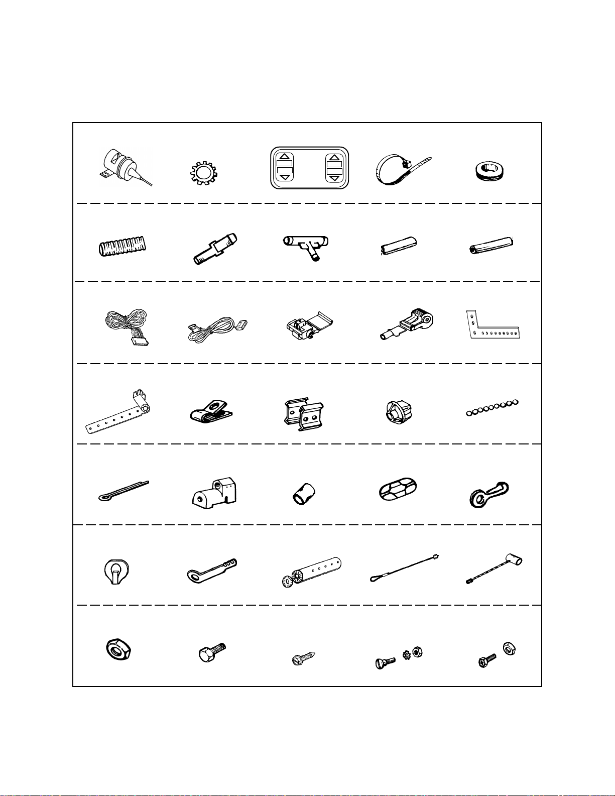
PARTS LIST
Servo Assembly
( 1 )
- 1 - - 4 - - 5 -
Convoluted tubing
( 1 )
- 6 - - 7 - - 8 - - 9 - - 10 -
Main Wiring Harness
( 1 )
- 11 - - 12 - - 13 - - 14 - - 15 -
Adjustable cable
mounting bracket assy.
( 1 )
M6 external tooth
star washer
( 3 )
- 2 -
Vacuum hose reducing
nipple
( 1 )
Fused wire with switch
connector
( 1 )
Assorted tube clamps
(4)
Dash Mounted control switch
( 1 )
ACC
CRUISE
ON
OFF
AUDIOVOX
CONTROL
RES
SET
CST
- 3 -
Assorted Vacuum
T - Connectors
Scotch lock connectors
( 4 )
Parallel throttle cable
clamps
( 1 )
Tie Straps
( 10 )
Vacuum Hose - Short
( 1 )
Female T- tap terminal
( 1 )
GM style threaded
snap in cable anchor
( 1 )
1/2" rubber bulkhead
grommet
( 1 )
Vacuum Hose - Long
( 1 )
“L” Bracket
( 1 )
Bead chain
( 1 )
- 16 - - 17 - - 18 - - 19 - - 20 -
Cotter pin
Ford snap on throttle
( 1 )
- 21 - - 22 -
GM throttle clip
( 1 )
adaptor
( 1 )
3 bead connector
( 1 )
Bead chain coupling
sleeves
( 2 )
- 23 -
Throttle mounting
bracket with locking
Bead chain coupling
( 2 )
- 24 -
Throttle wire loop
( 1 )
Bead chain eyelet
Barrel wire adaptor
washer
( 1 )
- 26 - - 27 - - 28 - - 29 - - 30 -
M6 hex nuts
( 3 )
M6 x 5/8" long
hex head bolt
( 3 )
M6 x 3/4" long hex
washer head sheet
metal screw
( 4 )
Slotted head shoulder
bolt with lock washer
and hex nut
( 1 )
M5 Phillips hex head
bolt with hex nut
-2-
connector
( 1 )
- 25 -
( 1 )
( 1 )
- 35 -- 34 -- 33 -- 32 -- 31 -
Page 5
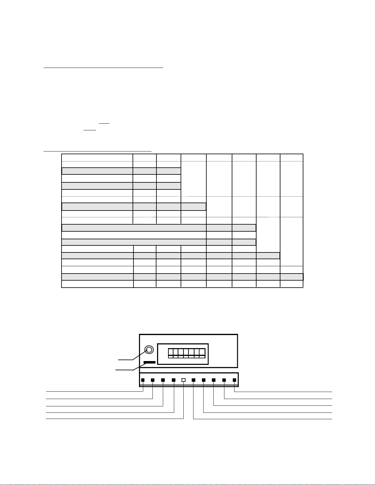
PROGRAMMING THE SERVO ASSEMBLY
To ensure that the cruise control operates smoothly and safely in your vehicle, the servo assembly must be
programmed. In order to properly program the servo assembly, you will need to know the number of cylinders,
the type of transmission (manual or automatic), if your vehicle is equipped with a Vehicle Speed Sensor (VSS),
and if so, the number of Pulses Per Mile ( PPM ), also if the cruise control switch is the open or closed circuit
style. The dash mount control switch supplied is the open circuit style switch. SW6 should be set to OFF.
Refer to the enclosed reference manual for information of VSS and PPM that applies to your vehicle. If there
is no VSS signal in your particular vehicle then the Magnet Kit must be used. Mount one magnet to the drive
shaft if the vehicle is rear wheel drive and set PPM to 2000. Mount 2 magnets to the drive shaft at 180° apart
if the vehicle is front wheel drive and set PPM to 2000. Note: When using magnets set Dip Switch #3 to "ON".
The sensitivity settings, control the amount of vacuum needed to keep the set speed constant. Remove the
( 2 ) screws securing the plastic cover on the back of the servo assembly to gain access to the dip switches.
DIP SWITCH PROGRAMMING TABLE: Follow the chart below to program the servo assembly.
SW1 SW2 SW3 SW4 SW5 SW6 SW7
PPM
2,000 OFF OFF
4,000 ON OFF
5,000 OFF ON
8,000 ON ON
SPEED SIGNAL
TACH ONLY OFF
VSS or MAGNETS ON
SENSITIVITY
LOW (
MEDIUM (
HIGH
LIGHT VEHICLES W/HIGH HORSE POWER) ON OFF
MOST VEHICLES) OFF OFF
(LOW POWER VEHICLES/HEAVY VEHICLES) OFF ON
CONTROL SWITCH
NORM. CLOSED ON
NORM. OPEN OFF
TACH SOURCE SELECT
ECM OFF
COIL ON
* When changing dip switch setting, make sure the 10-pin connector is unplugged from module.
MANUAL / AUTOMATIC TRANSMISSION SELECT
WHEN INSTALLING THIS KIT INTO VEHICLES THAT HAVE A MANUAL TRANSMISSION, YOU MUST
REMOVE THE BLACK JUMPER CONNECTOR LOCATED TO THE LEFT SIDE OF DIP SWITCH #1.
NOTE: If the vehicle is a manual transmission and does not have a VSS wire, the cruise will operate from tach
signal only. Program dip switch #1 and #2 for 4000 PPM and move dip switch #3 to OFF position.
LED
JUMPER
#1 - BROWN - IGNITION POWER
#2 - GREY - SPEED
#3 - RED - BRAKE
#4 - PURPLE - BRAKE
#5 - (NOT USED)
ON
OFF
1 2 3 4 5 6 7
#10 - BLUE - TACH.
#9 - BLACK - GROUND
#8 - GREEN - SET
#7 - (NOT USED)
#6 - YELLOW - RESUME
-3-
Page 6
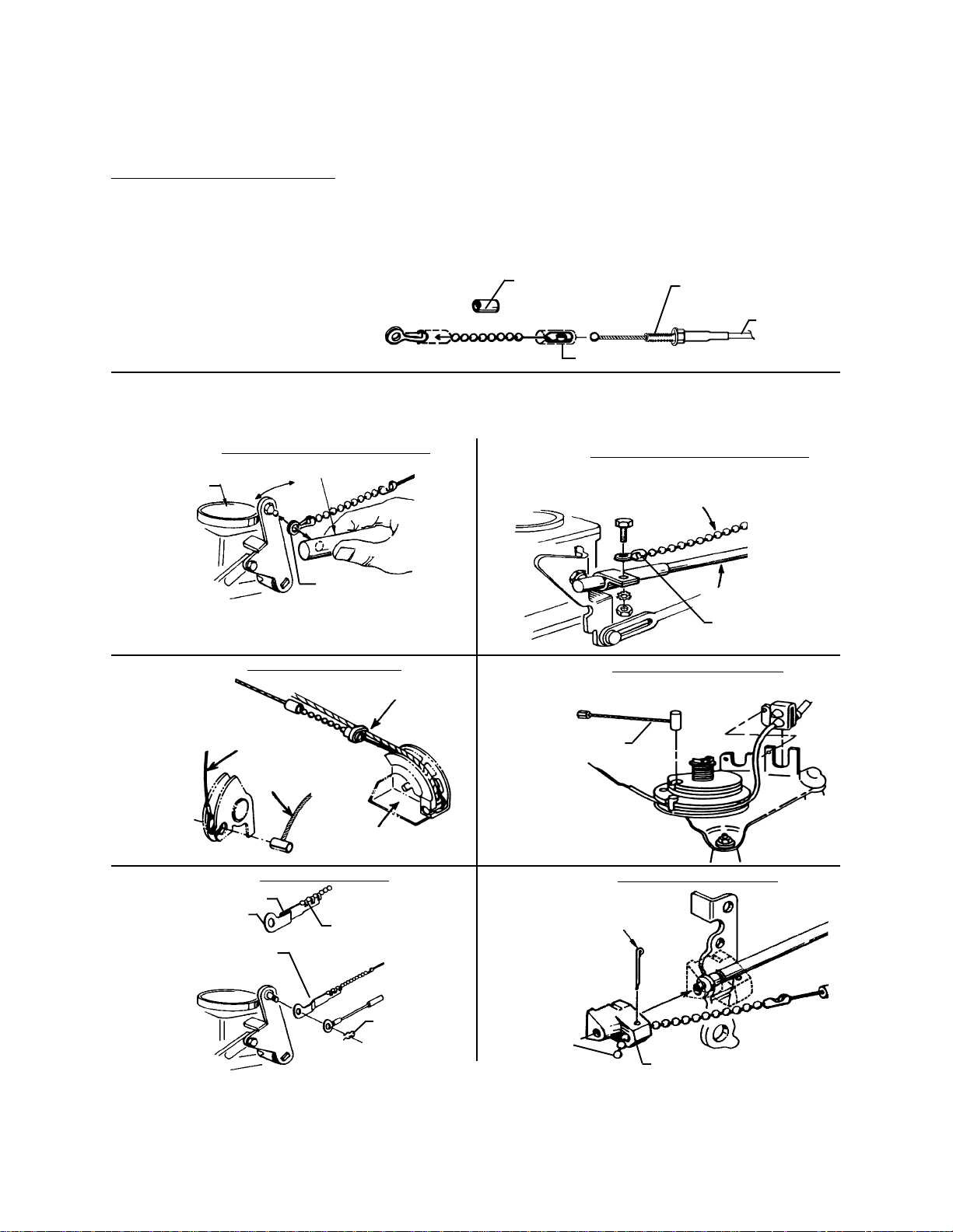
UNDER HOOD INSTALLATION
Connecting the Cruise Control Cable to the Throttle
NOTE: Prior to attaching servo cable to throttle, locate an accessible area to mount the cruise control servo,
but do not mount it. Leave the servo in this area (unmounted) and route cable to throttle attachment area.
CAUTION: Attach the cruise control cable so that it parallels the existing throttle cable as nearly as possible.
Choose a mounting method from the figures below:
FIG. 1
The bead chain and servo cable end must be
inserted into the bead chain connector. Then the
bead chain coupling sleeve must slide over
bead chain connector to insure that the end will
not hang in the connector.
Determine a suitable point on the throttle linkage to mount the cable connector. The mounting point chosen should have between
1-1/2" to 2" total linkage travel. It must operate smoothly by hand. There should be at least 5 beads between the throttle connector and
servo cable end. The cable must pull in a straight line from throttle linkage. Some vehicles that do not have enough total linkage travel
have to be connected at the accelerator pedal.
FIG. 2
Carburetor
Pull off Throttle Arm and Insert Bead Chain Connector between it
and Carburetor Arm. Be sure additional thickness of adaptor does
not bind linkage.
SNAP-ON THROTTLE ARM MOUNT
Existing Snap-On Throttle Arm On Vehicle
Bead Chain Eyelet
Connector (#25)
WIRE LOOP FOR PULLEY
Rubber Ring
Bead Chain
Coupling Sleeve (#23)
FIG. 3
FIG. 5FIG. 4
Attachment area for
securing cable
Cable
Bead Chain Coupling (#24)
CLAMP-ON THROTTLE ARM MOUNT
Cable Must Be within 20° of
same angle as Throttle Rod
20°
Bead Chain Eyelet
Connector (#25)
WIRE BARREL FOR PULLEY
Throttle Wire Loop
(#29)
Throttle Cable
FIG. 6
Double fold to shorten
3 Bead Connector
(#27)
Bend to clear Throttle Cable
Throttle Arm
3 BEAD CONNECTOR
Crimp with pliers
Throttle Cable
Throttle Clip
(#26)
Barrel Wire Adaptor
(#30)
FIG. 7
Cotter Pin (#21) locks Bead
Chain to Linkage Adaptor
Bead Chain
(#20)
-4-
FORD LINKAGE ADAPTOR
Snap-on Throttle Adaptor (#22)
Page 7

FIG. 8 FIG. 9
FLEX CABLE CONDUIT MOUNTING
FLEX CABLE MOUNTING TECHNIQUE
ALTERNATE
Select a location
which provides
1-3/4" travel
to match actuator.
FIG. 10
Carburetor
4"R Min.
Mounting Bracket used to
lock down carburetor end
of flexible cable (bend as
required).
Tube Clamp
(#17)
ALTERNATE
FLEX CABLE MOUNTING TECHNIQUE
Existing
Sheet Metal
Bracket
FIG. 11
Parallel Throttle Cable Clamps
(#18) used to lock cable end to
existing throttle housing
THREADED SNAP-IN ADAPTOR
Snap-in Cable Anchor (#19)
FIG. 12
Cable Anchor Point
Slotted Head Shoulder Bolt
Bead Chain
Eyelet Connector
(#25)
Bead Chain
Coupling Sleeve
(#23)
PEDAL PULL
Tube Clamp
(#34)
Tube Clamp
(#17)
Hex Nut & Lockwasher
Module Cable MUST extend past Adaptor
Connector
Bead Chain
Throttle Clip (#26)
Three Bead Connector
(#27)
Bead Chain (#20)
-5-
Page 8

CAUTION ! ATTACH THE CRUISE CONTROL CABLE SO THAT IT PARALLELS THE EXISTING THROTTLE CABLE AS
NEARLY AS POSSIBLE.
WARNING ! AFTER ATTACHING THE CRUISE CONTROL CABLE TO THE VEHICLE’S THROTTLE, OPERATE THE
THROTTLE MANUALLY ( FULL TRAVEL ) FROM BOTH UNDER HOOD AND ACCELERATOR PEDAL TO BE
ABSOLUTELY SURE THAT NONE OF THE CABLE ATTACHMENT COMPONENTS OR BEAD CHAIN CAN
RESTRICT OR INTERFERE WITH THE NORMAL THROTTLE OPERATION.
Mounting the Servo Assembly
1. Plug the 10 pin connector from the main harness into the mating connector on the servo assembly, arrange
the wires so that they do not cross over one another, and replace the plastic cover with the ( 2 ) screws
previously removed.
2. A) When selecting the location for the servo, make sure that the cable routing follows a smooth path, with
no sharp bends. You must also be sure that the cable is routed away from any hot, sharp, or moving
components within the engine compartment.
B) This unit has rapid response valves inside the servo which constantly operate during cruise operation.
To prevent noise transferring to inside the passenger compartment we strongly recommend this unit NOT
be mounted to the fire wall.
3. Using ( 2 ) of the M6 x 3/4" long hex washer head sheet metal screws, mount the servo to the selected location.
Do Not mount servo on the engine !
4. Attach the eyelet terminal on the end of the Black wire to a solid chassis ground bolt within the engine
compartment.
Connecting the Vacuum Hose
1. Plug the vacuum hose onto the servo assembly.
2. Route the vacuum hose to an existing vacuum hose that has constant vacuum while the engine is running
at idle, trim the hose to length, and make the attachment using the appropriate size T connector from the
kit.
See Diagrams below for common vacuum source connection.
Manifold Vacuum Tree
Remove cap and
use vacuum port
for Cruise Control
vacuum
Existing Vacuum Line
Factory Installed Tee
Remove cap and use
Vacuum Tee for Cruise
Control vacuum
Reducer-Tube
Vacuum Line
Tee-Tube
Tube Vacuum
Tube Vacuum
WARNING ! NEVER CUT OR ATTACH TO THE POWER BRAKE BOOSTER VACUUM HOSE.
Vacuum Test
Look for the vacuum hose coming directly from the intake manifold.
Run the engine at idle, and place your finger over the selected vacuum source. You should feel a strong suction
on your finger. Remove your finger and a noticeable change in engine RPM or engine smoothness should
result. Note: This vacuum source must maintain at least a minimum of 6 inches of mercury vacuum. If the
vacuum is lower than 6 inches while the pedal is depressed, then a vacuum canister must be used.
-6-
Page 9

Routing the Main Wiring Harness
1. Locate your vehicle by make, model, and engine size in the included Reference Manual in order to identify the
location of the VSS and Tach connection locations. If your make and model cannot be located, then the Magnet
Kit must be installed. Follow the installation instructions included in this manual.
In all cases, you will need to route the Brown, Green , Purple, Yellow, and Red wires through the bulkhead
to the passenger compartment of the vehicle.
The Blue wire will need to be routed to the tach location, and the Grey & Black twin lead will need to be routed
to the VSS or magnet speed sensor location. If either of these locations are in the passenger compartment,
they will need to be routed with the Brown, Green , Purple, Yellow, and Red wires.
2. Route the wires that will pass through the bulkhead away from any hot or moving components within the
engine compartment, and be sure that they are routed to a point lower than the grommet that will be used
for entrance into the passenger compartment. This will prevent water from running along the wires and into
the passenger compartment.
NOTE : FOR EASE OF INSTALLATION, YOU SHOULD USE AN EXISTING RUBBER GROMMET WHEN
PASSING WIRES THROUGH THE BULKHEAD.IF AN EXISTING GROMMET IS NOT AVAILABLE,
CAREFULLY DRILL A 1/2" WIRE ENTRANCE HOLE IN THE BULKHEAD, AND USE THE RUBBER
GROMMET SUPPLIED IN THE KIT.
3) Squeeze tab into
connector with pliers
4) Bend cover over
and snap shut
1) Press existing vehicle wire
into connector slot
2) Insert cruise control harness wire
to Stop - Must go past metal tab
WIRING CONNECTIONS
1. Blue Wire : Connect this wire to the vehicle’s negative side of the ignition coil using the blue Female T tap
terminal provided.
2. Grey and Black Pair Wires : 1) If the vehicle has VSS wire then remove spade terminal and connect the grey
wire to the vehicles VSS wire using the red scotch lock connector provided. The black wire is not used.
2) If the vehicle has no VSS wire then connect both the black spade terminal and the grey spade terminal
to the magnet speed sensor.
3. Purple Wire : Connect this wire to the vehicle’s brake light wire at the brake light switch. ( This is the wire that
turns the brake lights on when the brake pedal is pressed ). This wire will show +12 volts when the brake pedal
is pressed and 0 volts when released. See diagram below.
4. Red Wire : Connect this wire to the constant + 12 VDC battery source to the brake light switch. ( This is the
wire that remains at 12 volts whether the brake pedal is pressed or not ). See diagram below.
RED
Constant 12V
PURPLE
12V only when brake is depressed
-7-
Page 10

5. Locate the fused wire with switch connector included in the kit, and load the Brown, Green, and Yellow wires
from the main harness into the 4 pin switch connector. Be sure to load the wires according to the color coded
label on the connector, and press the terminals in fully until a click is heard.
6. Orange Wire : Connect the Orange wire from the fuseholder to a wire in the vehicle that shows + 12 VDC when
the ignition key is switched On and 0 VDC while cranking and when the key is switched OFF. Use a blue scotch
lock connector to make this connection.
DASH MOUNTED (norDASH MOUNTED (nor
DASH MOUNTED (nor
DASH MOUNTED (norDASH MOUNTED (nor
CRUISE COCRUISE CO
CRUISE CO
CRUISE COCRUISE CO
INSTINST
INST
INSTINST
1. Choose a flat location on the dashboard that is visible while driving. The location should be very accessible
to the driver, allowing easy activation of the switch while operating the cruise control. A template has been
provided to confirm that there is adequate space for mounting the switch in the selected location. (Fig.1)
2. After the location is selected, check the area behind the panel to be sure that the wires can be routed to the
cruise control harness connector. You should also make sure that the drill will not damage any components
or wiring behind the panel, and it is always best to remove the panel before drilling.
3. Drill (2) 1/4" diameter holes in the location marked on the template. After drilling, use a file or razor knife
to remove the dash material between the (2) holes.
4. Clean the area of the dashboard where the switch will be mounted, and allow any cleaning fluids to dry
completely.
5. Pass the wires from the switch through the hole in the panel, remove the paper lining from the mounting pad
on the back of the switch, properly align the switch, and firmly press in place on the panel. (Fig.2)
6. Route the 6 wires from the switch to the control switch connector from the cruise control main wiring harness.
Be sure to avoid any sharp or moving surfaces when routing wires, and secure the wires along their path
using tie straps.
NTRNTR
NTR
NTRNTR
ALLAALLA
ALLA
ALLAALLA
mally open)mally open)
mally open)
mally open)mally open)
OL SWITCHOL SWITCH
OL SWITCH
OL SWITCHOL SWITCH
TITI
OO
O
OO
NN
N
NN
TI
TITI
7. Plug the terminated ends of the Red, Brown, Green and Yellow wires into the color coded locations on the
connector. Be sure that the terminals click, and are fully seated in the connector. (Fig.3)
8. Plug the switch connector into the mating connector on the main cruise control harness.
9. Connect the Black wire from the switch to a known chassis ground source.
10. Connect the Grey wire from the switch to the parking light wire in the vehicle. When probed, the parking
light wire will read +12 VDC when the parking lights are on, and 0 VDC when the parking lights are off.
The Grey wire controls the backlighting of the switch, and the switch will not illuminate if the Grey wire is left
disconnected. You must connect all other wires from the switch, or the cruise control will not operate.
-8-
Page 11

Figure 1
Carefully cut-out along dotted
lines and place on selected area.
Use a file or razor knife to remove
the material between the 2 holes.
DASH BOARD TEMPLATE
Drill 1/4" Dia. holes, (2 places).
Figure 2
DASH
Figure 3
CONTROL SWITCH MOUNTING
TEMPLATE CUT-OUT
ACCEL
RES
SET
COAST
ON
OFF
CRUISE
CONTROL
CONTROL SWITCH CONNECTIONS
CONNECTOR
1
2
3
RED
BROWN
GREEN
YELLOW
4
CONTROL SWITCH
-9-
Page 12

ROAD TESTING THE CRUISE CONTROL
Be sure to fully test all functions of your new cruise control on a level surface away from predestrian and vehicle
traffic. While travelling 35 M.P.H. turn switch on , then press Set button. Unit will engage when Set button is
released. To disengage, tap on brake or turn switch off - cruise will disengage. Follow same procedure at 45
M.P.H. and at 55 M.P.H. If unit is inoperative, open cover on cruise and look at the L.E.D. Press Set button,
L.E.D. should light. Press Resume button, L.E.D. should light.Step on the brake, L.E.D. should light. If L.E.D.
does not light then check wiring. If the vehicle’s speed drops considerably when travelling up hills, you may
need the optional vacuum booster canister. Call 1 - 800 - 225 - 6074 for additional assistance.
ON / OFF : Move the ON / OFF switch to the ON position. Nothing will happen, as this simply prepares the
system for operation.
Each time the ignition switch or the cruise control switch is turned OFF, the system is de - energized. To reenergize the system, the ignition switch must be turned on, and the cruise control switch must be moved to
the ON position. The cruise control switch can be left On at all times without causing any damage to the system.
SET SPEED : After turning the system On, wait at least 3 seconds before attempting to set your speed. To
operate the system, drive the car at a steady speed above 35 M.P.H.
Press the SET / COAST switch and release it, then slowly remove your foot from the accelerator pedal. Your
SET SPEED is now programmed into the cruise control’s memory, and your driving speed should remain within
2 M.P.H. of your set speed.
If you want to increase your speed, simply press on the accelerator pedal. When you release the pedal, you
will return to your original SET SPEED.
ACCEL : You can increase your SET SPEED using the RESUME / ACCEL feature. Your vehicle will accelerate
as you hold this switch to the RESUME / ACCEL position. When you release the switch, your SET SPEED will
be re - programmed to the present speed of the vehicle.
TAP UP : You can also increase your SET SPEED gradually by quickly pressing and releasing the RESUME/
ACCEL switch. Each time you press and release the switch, your speed will increase by approximately 1/2
M.P.H.
TAP DOWN : You can also decrease your SET SPEED gradually by quickly pressing and releasing the SET/
COAST switch. Each time you press and release the switch, your speed will decrease by approximately
1/2 M.P.H.
COAST : To reduce your SET SPEED, press and hold the SET / COAST button. This erases the previously
programmed SET SPEED, and allows the vehicle to coast. Just before slowing to the speed you want, release
the button. Your present speed will be re - programmed as the new SET SPEED, providing the vehicle is
traveling faster than 35 M.P.H.
RESUME : Whenever you use the brake pedal to slow or stop the vehicle, the cruise control will disengage
but retain the programmed SET SPEED. To return to the SET SPEED, accelerate to a speed above 35 M.P.H.,
then press and release the RESUME / ACCEL switch. The vehicle will automatically accelerate to the
programmed SET SPEED, and hold that speed.
When using the RESUME feature with standard transmission, you should be in the correct gear for your SET
SPEED.
DISENGAGE : You can disengage from the SET SPEED in two or three ways, depending on the type of
transmission ( manual or automatic ) in the vehicle.
- Gently tap the brake pedal to activate the brake lights.
- Turn the control switch to the OFF position.
- For manual transmissions, depress the clutch. This will cause the engine to rev slightly before disengaging.
-10-
Page 13

TROUBLE SHOOTING
WIRING - 10 PIN CONNECTOR
Note : If the brown, green, or yellow wires do not test properly, proceed immediately to the testing of the
4 pin control switch testing.
POS WIRE COLOR FUNCTION
9 Black Always continuity to ground
3 Red Always + 12 VDC
1 Brown + 12 VDC with Ignition switch and cruise control switch ON.
O VDC with Ignition switch or cruise control switch OFF.
4 Purple + 12 VDC when the brake pedal is pressed.
0 VDC when the brake pedal is released.
To test the Green and Yellow wires, the Ignition Switch and Cruise Control Switch must both be turned on and
left ON.
8 Green + 12 VDC when the SET / COAST switch is pressed.
6 Yellow + 12 VDC when the RESUME / ACCEL switch is pressed.
OPEN CIRCUIT SWITCH
0 VDC when the SET / COAST switch is released.
0 VDC when the RESUME / ACCEL switch is released.
CLOSED CIRCUIT SWITCH
8 Green 0 VDC when the SET / COAST switch is pressed.
+12 VDC when the SET / COAST switch is released.
6 Yellow + 12 VDC when the RESUME / ACCEL switch is pressed.
0 VDC when the RESUME / ACCEL switch is released.
10 Blue Engine RPM. Increasing AC Voltage with engine speed.
2 Grey Vehicle Speed Sensor:
Factory VSS: Roll vehicle forward (approx. 3 feet), in neutral with
Ignition and Cruise Control On. L.E.D. should flash.
Magnets or Fords: Drive at 30 M.P.H. approx. 500-1000 milivolts
AC.
4 PIN CONTROL SWITCH TESTING
Red - +12 VDC with Ignition Switch ON.
Brown - Same as Pos 1 above.
Green - Same as Pos 8 above.
Yellow - Same as Pos 6 above.
-11-
Page 14

MM
AA
GNET KITGNET KIT
M
A
GNET KIT
MM
AA
GNET KITGNET KIT
INSTINST
INST
INSTINST
MAGNET AND SPEED SENSOR COIL INSTALLATION
The magnets, along with the speed sensor coil provide pulses to calculate road speed for the cruise control.
When the drive shaft rotates, the magnets attached to it move by the speed sensor coil. This generates electrical
pulses which are monitored by the cruise control.
This installation will require access to the vehicles drive shaft/axle. The drive wheel end of the vehicle will need
to be lifted-up and supported with jack stands. IF YOU CANNOT SAFELY INSTALL THE MAGNET AND
SPEED SENSOR COIL YOURSELF, THEN WE RECOMMEND THAT YOU HAVE IT INSTALLED BY A
QUALIFIED PROFESSIONAL.
MAGNET LOCATION:
Rear wheel drive vehicles: Magnet location is not to exceed 12 inches (30 cm) from the front (transmission end)
universal joint, or damage may result from the lateral movement of the drive shaft. See Figure 1.
Front wheel drive vehicles: Select either the right or left axle shaft near the transmission housing. Select the
side with the best accessibility, and insure there is adequate clearance for the mounting magnets and speed
sensor coil. See Figures 6 or 7.
NOTICE: It is important to keep the magnets as close to the transmission's housing as possible. Leave
adequate clearance from the catalytic converter and exhaust pipes.
Step 1: Clean the magnet mounting location. Use coarse sandpaper or a wire brush to clean the axle surface.
Complete by wiping with cleaning solvent.
Step 2: Rear wheel drive vehicles require one magnet to be secured to the drive shaft.
Front wheel drive vehicles require two magnets to be secured to the drive axle.
ALLAALLA
ALLA
ALLAALLA
TITI
TI
TITI
OO
O
OO
NN
N
NN
Step 3: Cut a 2" strip of paper approximately 11" long. Wrap this strip around the drive shaft and mark paper
as shown in Figure 2. This will give you the total distance around the drive shaft (circumference). Cut the strip
at this mark.
Step 4: Measure length of the strip and divide this number by the number of magnets (per Step 2) your vehicle
requires. Mark these locations on the strip. These are the center lines for the magnets.
Step 5: Tape the strip around the drive shaft at the location chosen for the magnets. Remove backing paper
from double sided foam and press onto the magnet. Remove remaining strip of backing paper and place the
magnet or magnets on the cleaned drive shaft/axle, not the paper. Be sure magnet tabs are lengthwise on the
shaft. See Figures 4 or 9. Then remove the paper strip.
-12-
Page 15
Step 6: While rotating the shaft, carefully snap one wire into one set of magnet slots. Loosely wrap the wire
to hold it in place. Snap the second wire into the remaining slots making sure the ends are nearly opposite
the first wire, as shown in Figure 4 or 11.
Step 7: Carefully pull wires tight, and twist with a pair of pliers, pulling down as you twist to avoid breaking
the wire. Now take the loose ends and wrap through the opposite wire, and twisting as above to remove any
excess slack, see Figure 4. This procedure will secure the magnets onto the drive shaft. The double-faced
tape is used to temporarily hold the magnets until the wire is attached.
Step 8: Spin the drive shaft by hand and check to ensure proper clearance. Remember that the drive shaft
position will change with the suspension. See Figures 3 or 8.
SPEED SENSOR COIL INSTALLATION
Step 9: Assemble the speed sensor coil and bracket with nut and lock washer. Use of mounting bracket will
be determined by the specific installation. Refer to Figures 5 or 10. In some cases installation may be easier
if the bracket is bent or cut to a specific shape.
Step 10: Determining the location for the speed sensor/bracket assembly: The speed sensor coil must be
pointing directly at the centerline of the shaft leaving a 3/8" (10 mm) clearance between the speed sensor coil
and the magnets. See Figures 8.
CAUTION: Before drilling any holes, make sure there are no parts which may be damaged on the other side
of the metal. Double check for any wiring harness which might be easily damaged by the drill bit.
Step 11: Use the bracket as a template to mark and center punch two hole locations. Drill two 3/16" diameter
holes. Mount the speed sensor/bracket assembly using two 1/4" x 3/4" sheet metal screws. Be sure bracket
is mounted securely so it will not vibrate during vehicle movement.
NOTICE: If the speed sensor coil is closer than 1/4", there is a possibility that the magnets will strike the coil.
If the coil is more than 1/2" from the magnets, the cruise control may not function properly.
NOTE: Make sure the black and gray wires are routed clear of any hot or moving parts as well, away from
electrical items such as spark plug wires or ignition systems. Interference from these sources could cause
the cruise control to surge.
WIRING:
Step 12: Route the black and gray paired wires to the speed sensor coil and attach to the terminals. (It does
not matter which way the wires are attached, i.e.polarity).
NOTE: This magnet kit cannot be used on Honda vehicles.
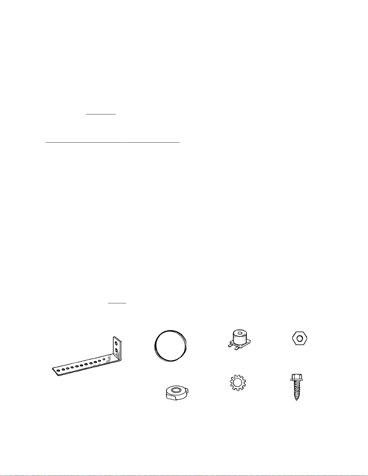
MAGNET KIT HARDWARE:
Speed Sensor Bracket
Stainless Steel Wire
Speed Sensor Coil
6mm Hex Nut
1/4" x 3/4"
6mm Lockwasher
Sheet Metal Screw
Magnet with Holder
-13-
Page 16

INSTALLATION - REAR WHEEL DRIVE VEHICLES
DRILL 3/16" DIA HOLES IN
FLOOR PAN OF VEHICLE
EXISTING CABLE OR
BRACKET ON VEHICLE
DRIVE SHAFT
12" MAX. DISTANCE
FROM U-JOINT
CUT STRIP ALONG THIS LINE
Figure 2
Figure 1
FABRICATED BRACE TO
STIFFEN PICK-UP COIL
BRACKET
CLEARANCE 3/8"
PULL
TIGHT
CABLE TIE
VEHICLE FLOOR
POSITION SPEED SENSOR HORIZONTALLY
TO ALLO W FOR UP AND DOWN MO TION OF
1/2"
DRIVESHAFT
Figure 3
DRIVE SHAFT
Figure 4
PICK-UP COIL AND BRACKET ASSEMBLY
Figure 5
-14-
Page 17

TRANSMISSION
AXLE HOUSING
INSTALLATION - FRONT WHEEL DRIVE VEHICLES
DRILL OR FILE BRACKET TO FIT
EXISTING BOLT
3/8"
DIA. OF
MOUNTING SURFACE
WIRES AND MAGNET
RIGHT FRONT
AXLE ONLY
Figure 6
3/8"
1/2"
Figure 8
Figure 7
MAGNET
MAGNET
Figure 9
Figure 10
Figure 11
-15-
Page 18

®
12 MONTH LIMITED WARRANTY
Applies to automotive speed controls.
AUDIOVOX CORPORATION (the Company) warrants to the original retail purchaser of this product that should
this product or any part thereof, under normal use and conditions, be proven defective in material or
workmanship within 12 months from the date of original purchase, such defect(s) will be repaired or replaced
with new or reconditioned product (at the Company's option) without charge for parts and repair labor.
To obtain repair or replacement within the terms of this Warranty, the product is to be delivered with proof of
warranty coverage (e.g. dated bill of sale), specification of defect(s), transportation prepaid, to an approved
warranty station or the Company at the address shown below.
This Warranty does not extend to the costs incurred for installation, removal or reinstallation of the product, nor
to any damage to the vehicle including its engine, drivetrain or electrical systems.
This Warranty does not apply to any product or part thereof which, in the opinion of the Company, has suffered
or been damaged through alteration, improper installation, failure to install in accordance with the Installation
Manual(s), mishandling, misuse, neglect, accident, or by removal or defacement of the factory serial number/
bar code label(s). THE EXTENT OF THE COMPANY'S LIABILITY UNDER THIS WARRANTY IS LIMITED TO
THE REPAIR OR REPLACEMENT PROVIDED ABOVE AND, IN NO EVENT, SHALL THE COMPANY'S
LIABILITY EXCEED THE PURCHASE PRICE PAID BY PURCHASER FOR THE PRODUCT.
This Warranty is in lieu of all other express warranties or liabilities. ANY IMPLIED WARRANTIES, INCLUDING
ANY IMPLIED WARRANTY OF MERCHANTABILITY, SHALL BE LIMITED TO THE DURATION OF THIS
WRITTEN WARRANTY. ANY ACTION FOR BREACH OF ANY WARRANTY HEREUNDER INCLUDING ANY
IMPLIED WARRANTY OF MERCHANTABILITY MUST BE BROUGHT WITHIN A PERIOD OF 30 MONTHS
FROM DATE OF ORIGINAL PURCHASE. IN NO CASE SHALL THE COMPANY BE LIABLE FOR ANY
CONSEQUENTIAL OR INCIDENTAL DAMAGES FOR BREACH OF THIS OR ANY OTHER WARRANTY,
EXPRESS OR IMPLIED, WHATSOEVER. No person or representative is authorized to assume for the
Company any liability other than expressed herein in connection with the sale of this product.
Some states do not allow limitations on how long an implied warranty lasts or the exclusion or limitation of
incidental or consequential damage so the above limitations or exclusions may not apply to you. This Warranty
gives you specific legal rights and you may also have other rights which vary from state to state.
AUDIOVOX CORPORATION, 150 MARCUS BLVD., HAUPPAUGE, NEW YORK 11788 l (516) 231-6051
-16-
Form. No. 128-4699
Page 19

Audiovox Corp., 150 Marcus Blvd., N.Y. 11788
Form No.128-4540C
 Loading...