

Audiovox BT1611i Owner's Manual

BT1611i
Owner's Manual
/
TUNE
BASS
SUB
RECORD
BT1611I MP3/WMA RECEIVER
MENU
AUX IN
INT
AM/FM/CD/MP3/WMA Receiver
with Bluetooth Technology

BT1611i
2
PREPARATION
Getting Started
Congratulations on your purchase of the Phase
Linear BT1611i Mobile AM/FM/CD/MP3/WMA
Receiver. It’s a good idea to read all of the
instructions before beginning the installation.
We recommend having your Phase Linear
BT1611i installed by a reputable installation
shop.
Contents
Installation Instructions.............................. 3
Wiring........................................................ 6
Operating Instructions............................... 7
Tuner Operation.......................................11
CD Player Operation............................... 13
MP3/WMA Operation .............................. 15
Using a USB Device or SD Card.............19
iPod Operation ........................................ 21
Bluetooth Operation ................................ 23
Remote Control....................................... 27
Care and Maintenance............................28
Troubleshooting....................................... 29
Specifications.......................................... 30
Installation Requirements
This unit is designed for installation in cars,
trucks and vans with an existing radio opening.
In many cases, a special installation kit will be
required to mount the radio to the dashboard.
These kits are available at electronics supply
stores and car stereo specialty shops. Always
check the kit application before purchasing to
make sure the kit works with your vehicle. If you
need a kit but cannot locate one, call our
customer support line at 1-800-323-4815.
(U.S.A. and Canada only.)
Tools and Supplies
The following tools and supplies are needed to
install the radio.
• Torx type, flathead and Philips screwdrivers
• Wire cutters and strippers
• Tools to remove existing radio (screwdriver,
socket wrench set or other tools)
• Electrical tape
• Crimping tool
• Volt meter/test light
• Crimp connections
• 18 gauge wire for power connections
• 16-18 gauge speaker wire
Speaker Requirements
Only connect speakers rated with a load
impedance of 4 ohms. Speakers with a load
impedance of less than 4 ohms could damage
the unit.
Disconnect Battery
Before you begin, disconnect the battery
negative terminal.
Toll-Free Installation Assistance
If you require assistance, contact Technical
Support at 1-800-323-4815 from 8:30 a.m. to
7:00 p.m. EST Monday through Friday and from
9:00 a.m. to 5:00 p.m. EST on Saturday.
(U.S.A. and Canada only.)
BT1611i
3
INSTALLATION INSTRUCTIONS
This unit is designed for installation in cars,
trucks and vans with an existing radio opening.
In many cases, a special installation kit will be
required to mount the radio to the dashboard.
These kits are available at electronics supply
stores and car stereo specialty shops. Always
check the kit application before purchasing to
make sure the kit works with your vehicle.
Pre-installation
1. Disconnect Battery
Before you begin, always disconnect the battery
negative terminal.
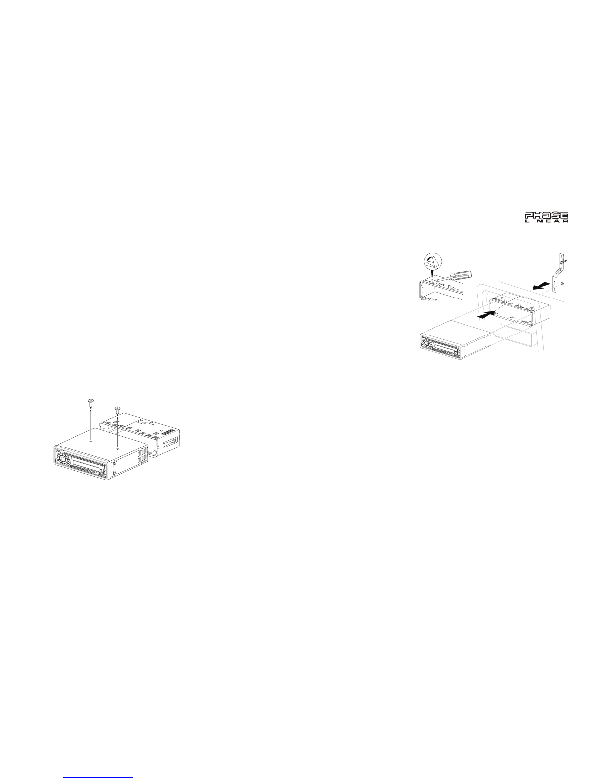
2. Remove Transport Screws
Universal Installation Using
Mounting Sleeve
1. Remove the detachable front panel, if it is
attached to the chassis, by pushing the
“Release” button.
2. Slide the mounting sleeve off of the
chassis if it has not already been removed.
If it is locked into position, use the removal
keys (supplied) to disengage it. The
removal keys are depicted on page 5.
3. Check the dashboard opening size by
sliding the mounting sleeve into it. If the
opening is not large enough, carefully cut
or file as necessary until the sleeve easily
slides into the opening. Do not force the
sleeve into the opening or cause it to bend
or bow. Check that there will be sufficient
space behind the dashboard for the radio
chassis.
4. Locate the series of bend tabs along the
top, bottom and sides of the mounting
sleeve. With the sleeve fully inserted into
the dashboard opening, bend as many of
the tabs outward as necessary to firmly
secure the sleeve to the dashboard.
5. Place the radio in front of the dashboard
opening so the wiring can be brought
through the mounting sleeve.
6. Follow the wiring diagram carefully and
make certain all connections are secure
and insulated with crimp connectors or
electrical tape to ensure proper operation.
7. After completing the wiring connections,
attach the front panel and turn the unit on
to confirm operation (vehicle ignition
switch must be on). If the unit does not
operate, recheck all wiring until the
problem is corrected. Once proper
operation is achieved, turn the ignition
switch off and proceed with final mounting
of the chassis.
8. Carefully slide the radio into the mounting
sleeve, making sure it is right-side-up, until
it is fully seated and the spring clips lock it
into place.
/
T
U
N
E
CD1211CDRECEIVER
SCAN
MONO
EQ
AUXIN
/
T
U
N
E
C
D
1
2
11
C
D
R
EC
EIVER
S
C
A
N
M
O
N
O
E
Q
AUXIN
BT1611i
4
9. Attach one end of the perforated support
strap (supplied) to the screw stud on the
rear of the chassis using the hex nut
provided. Fasten the other end of the
perforated strap to a secure part of the
dashboard, either above or below the
radio, using the screw and hex nut
provided. Bend the strap, as necessary, to
position it. CAUTION: The rear of the radio
must be supported with the strap to
prevent damage to the dashboard from
the weight of the radio or improper
operation due to vibration.
10. Re-attach the front panel to the chassis
and test radio operation by referring to the
operating instructions for the unit.
NOTE: For proper operation of the CD
player, the chassis must be mounted within
20° of horizontal. Make sure the unit is
mounted within this limitation.
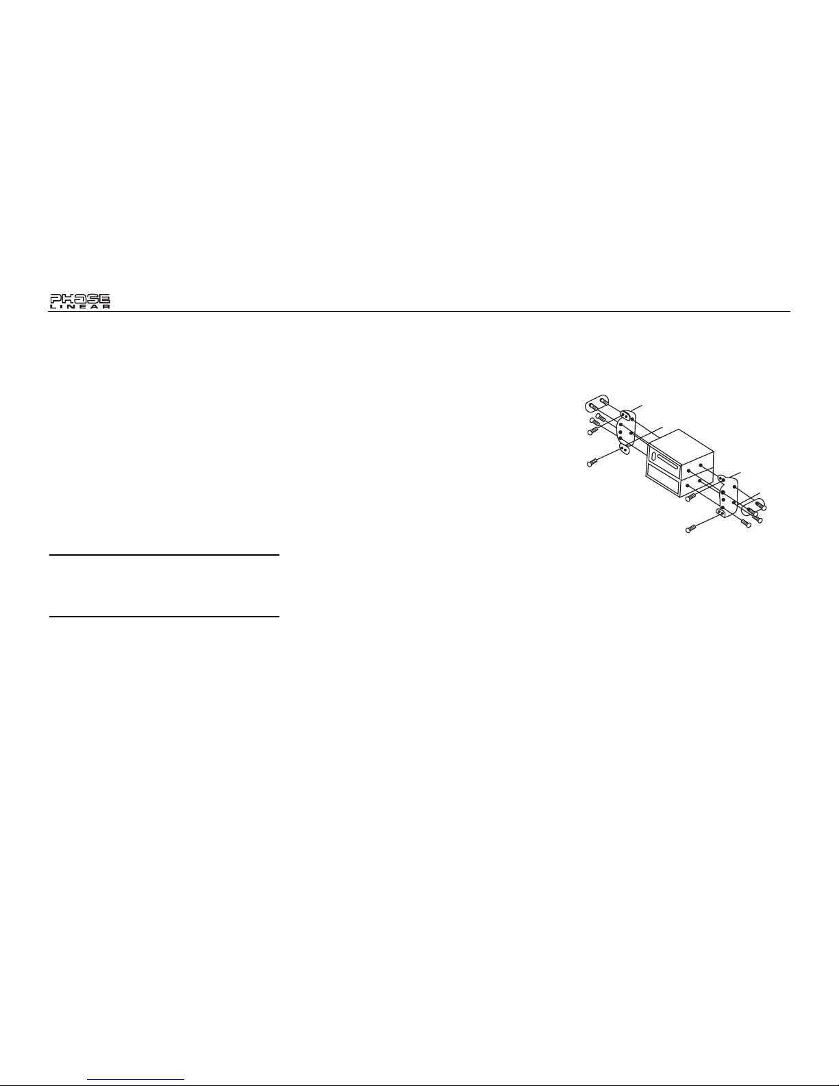
Kit Installation
If your vehicle requires the use of an installation
kit to mount this radio, follow the instructions
included with the installation kit to attach the
radio to the mounting plate supplied with the kit.
1. Wire and test the radio as outlined in the
Universal Installation instructions.
2. Install the radio/mounting plate assembly
to the sub-dashboard according to the
instructions in the installation kit.
3. Attach the support strap to the radio and
dashboard as described in the Universal
Installation instructions.
4. Replace the dashboard trim panel.
ISO Installation
This unit has threaded holes in the chassis side
panels which may be used with the original
factory mounting brackets of some vehicles to
mount the radio to the dashboard. Please
consult with your local car stereo shop for
assistance on this type of installation.
1. Remove the existing factory radio from the
dashboard or center console mounting.
Save all hardware and brackets as they
will be used to mount the new radio.
2. Carefully unsnap the plastic frame from
the front of the new radio chassis. Remove
and discard the frame.
3. Remove the factory mounting brackets
and hardware from the existing radio and
attach them to the new radio. Do not
exceed M5 x 9 MM maximum screw size.
Longer screws may damage components
inside the chassis.
4. Wire the new radio to the vehicle as
outlined in the Universal Installation
instructions.
5. Mount the new radio assembly to the
dashboard or center console using the
reverse procedure of step 1.
Reconnecting the Battery
When wiring is complete, reconnect the battery
negative terminal.
BT1611i
5
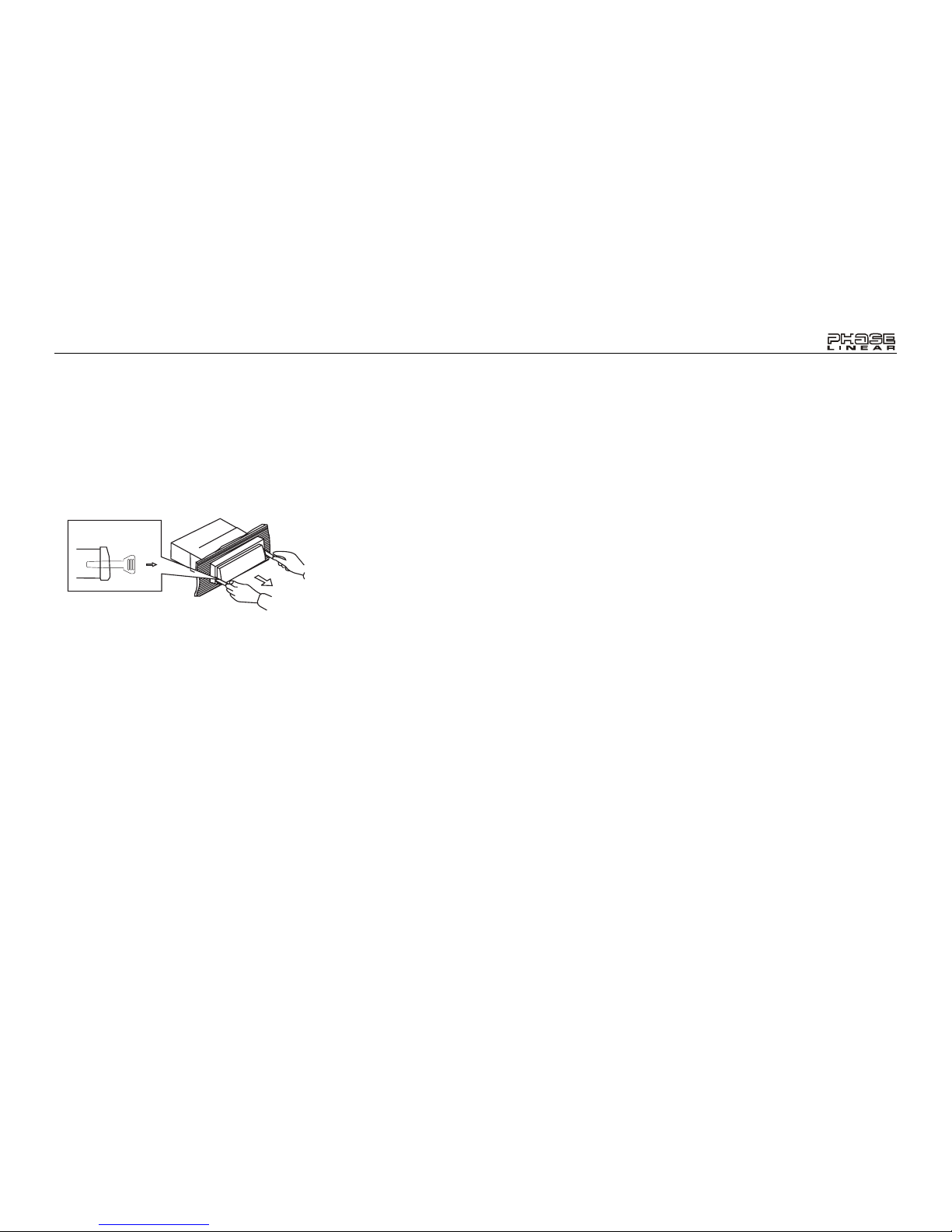
Removing the Radio
To remove the radio after installation, remove
the trim ring by lifting in the center and pulling it
off from either side. Insert the removal keys
straight back until they lock, and then pull the
radio out. If removal keys are inserted at an
angle, they will not lock properly to release the
unit.
Fuses
When replacing a fuse, make sure the new fuse
is the correct type and amperage. Using an
incorrect fuse could damage the radio. The
BT1611i uses one 15 amp fuse located below
the wiring connector (15 amp fast blow ATO).
Removal Key
BT1611i
6
Gray/Black (-)
Gray (+)
6
White/Black (-)
White (+)
Violet (+)
+
5
7
8
Green (+)
Green/Black (-)
Violet/Black (-)
Gray
9
11
13
15A
10
12
iPod NanoiPod MiniiPod
iPod Gen5
14
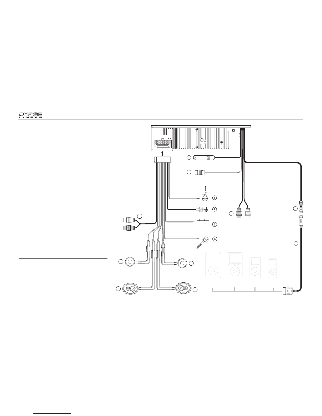
WIRING
1. Power Antenna (dark blue wire) - Connect
to the power antenna or an amplifier. If not
used, tape the bare end of wire.
2. Ground (black wire) - Connect to the
ground terminal or a clean, unpainted part
of the chassis.
3. Memory/Battery (yellow wire) - Connect to
the battery or to a 12 volt power source
that is always live. The radio will not work
if this wire is not connected.
4. Accessory/Ignition (red wire) - Connect to
the existing radio wire or radio fuse.
5. Left Front Speaker
6. Right Front Speaker
7. Left Rear Speaker
8. Right Rear Speaker
9. RCA Outputs to Amplifier
10. Auxiliary Input RCAs (yellow)
11. Antenna
12. Subwoofer Output (blue)
13. iPod/jLink connector - Use this 8-pin DIN
socket to connect your jLink iPod cable.
14. jLinkcable (iPod Cable)
NOTE: The amplifiers in this radio are only
designed for use with four speakers. Never
combine (bridge) outputs for use with two
speakers. Never ground negative speaker
leads to chassis ground. Failure to wire
exactly as shown may cause electrical
damage to the radio.
BT1611i
7
OPERATING INSTRUCTIONS
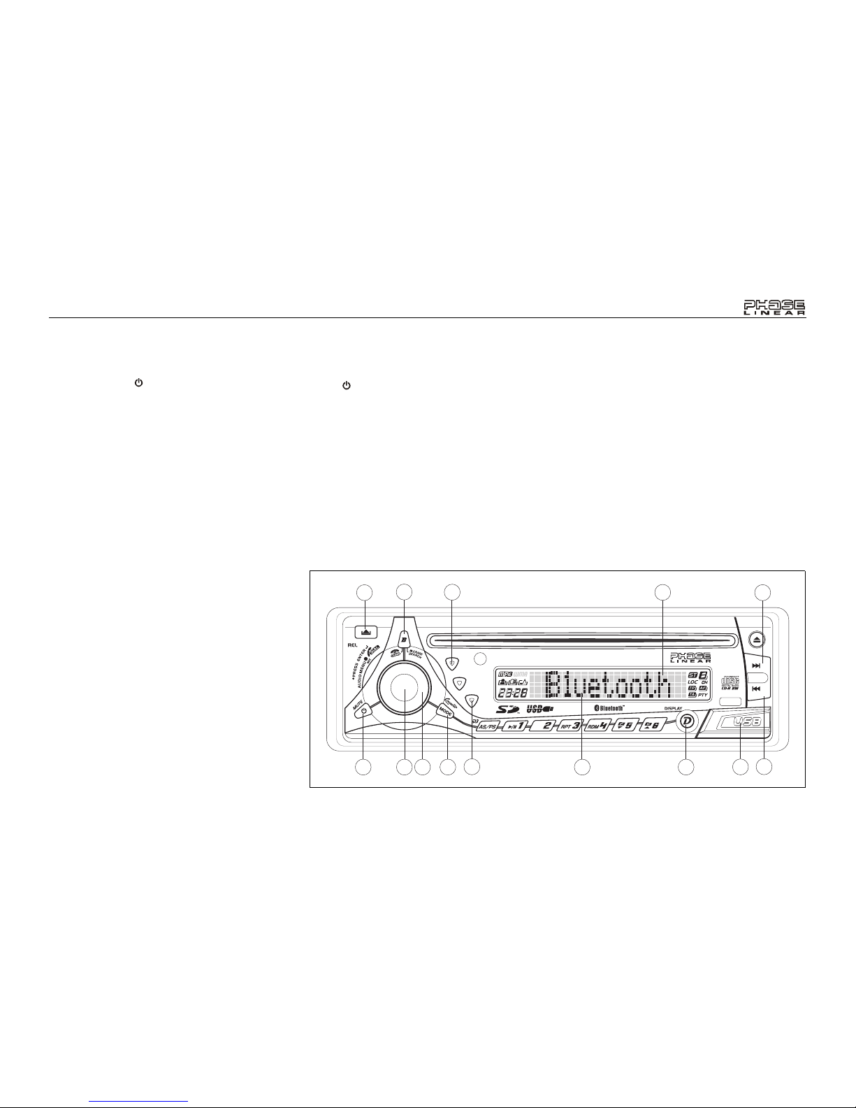
Power
Press the power button (1) or any other
button on the face of the receiver to turn the
unit on when the ignition switch is on. Press the
power button again to turn the receiver off. If
the radio was left on when the ignition was last
turned off, the receiver will turn on automatically
when the ignition switch is again turned on. If
the receiver was off when the ignition was last
turned off, the receiver must be turned on
manually when restarting the vehicle.
Mode
Press MODE (2) to select a different mode of
operation as indicated on the display panel.
Available modes include Tuner, CDP, USB
Host, SD/MMC, iPod and AUX. During CD
player operation, pressing MODE will change to
the tuner mode without ejecting the disc.
Volume
To increase the volume, turn the AUDIO
CONTROL (3) clockwise. To decrease the
volume, rotate the AUDIO CONTROL counter
clockwise. When volume is adjusted, the
volume level is shown on the display panel as a
number ranging from “00” (lowest) to “46”
(highest).
Audio Mute
Press /MUTE button (1) to mute the audio
volume. “Mute” flashes on the display. Restore
volume to the previous setting by pressing the
mute button again, adjusting the AUDIO
CONTROL, or by pressing any other button on
the unit.
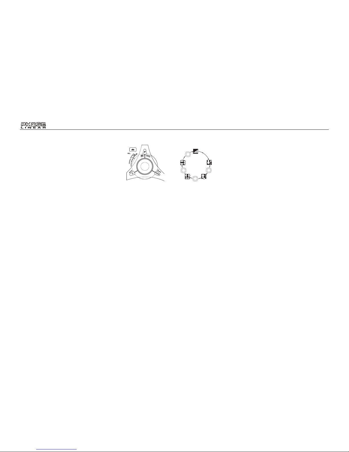
Audio Menu
Press and hold the AUDIO CONTROL button
(4) to access the Audio Menu. Press the
AUDIO CONTROL button repeatedly to step
through the menu of audio functions: volume,
bass, treble, balance, fader, and volume. When
adjusting audio functions, the unit will
automatically exit select mode and return to the
normal display after five seconds or when
another function is activated.
Bass
Press the AUDIO CONTROL button (4) twice
until “BASS” appears in the display. Within five
seconds, turn the AUDIO CONTROL (3) to
adjust the bass from “-6” to “+6”. “0” represents
a flat response. The bass level is shown on the
display for five seconds or until another function
is activated.
/
TUNE
BASS
SUB
RECORD
BT1611I MP3/WMA RECEIVER
MENU
AUX IN
1
9
10
8
19
5
4 32
7
14
13
15
18
INT
BT1611i
8
Treble
Press the AUDIO CONTROL button (4) three
times until “TREBLE” appears in the display.
Within five seconds, turn the AUDIO
CONTROL (3) to adjust Treble from “-6” to “+6”.
“0” represents a flat response. The treble level
is shown on the display for five seconds or until
another function is activated.
Balance
Press the AUDIO CONTROL button (4) four
times until “BALANCE” appears in the display.
Within five seconds, turn the AUDIO
CONTROL (3) to adjust the Balance between
the right and left speakers from “R12” (full right)
to “L12” (full left). “C00” represents an equal
balance level between the right and left
speakers. The balance position is shown on the
display for five seconds or until another function
is activated.
Fader
Press the AUDIO CONTROL (4) five times until
“FADER” appears in the display. Within five
seconds, turn the AUDIO CONTROL (3)
clockwise or counter clockwise to adjust
balance between the front and rear speakers
from “R12” (full rear) to “F12” (full front). “C00”
represents an equal balance level between the
front and rear speakers. The fader position is
shown on the display for five seconds or until
another function is activated.
System Menu
Press and hold the D/DISPLAY button (9) to
view the system “MENU”. Press the D/
DISPLAY button repeatedly or use the Up
Tuning >>| and Down Tuning |<< (14, 13)
buttons to access the following MENU options.
PAIRING
This feature is used to pair your mobile phone
to the unit’s Bluetooth system. To initiate the
pairing process select “Pairing” and then press
the AUDIO CONTROL button.
RE-CONN/DIS-CONN
Use this feature to reconnect or disconnect a
paired mobile phone manually. T urn the AUDIO
CONTROL (3) to select “RE-CONN” to reconnect or “DIS-CONN” to disconnect and then
press the AUDIO CONTROL button (4) to
perform the operation.
A ANSWER (On/Off)
Select “On” to automatically answer calls
without pressing the AUDIO CONTOL button
(4),
PHONE VOL (00-38)
Use this feature to set the default ringing
volume for all incoming calls. Use the AUDIO
CONTROL to adjust the ring volume from “00”
to “38”.
CONTRAST (00-10)
Use the AUDIO CONTROL to adjust the
contrast level from 00-10.
Clock FORMAT (12H/24H)
This option allows selection of a 12 Hour or 24
Hour clock format. The default clock format is
“12H”. Turn the AUDIO CONTROL to select the
“24H” format.
Clock SET
Turn the AUDIO CONTROL left to adjust the
hours and right to adjust the minutes.
AREA
Turn the AUDIO CONTROL to select the
appropriate frequency spacing for your area:
U.S.A., Latin, Europe, or Oirt (Russia).
Distant/Local
This feature is used to designate the strength of
the signals at which the radio will stop during
automatic tuning. “Distant” is the default setting,
VOL
VOLUME
BASS
TREBLE
BALANCE
FADER
P
U
S
H
S
E
E
L
C
T
B
B
S
L
E
T
A
A
A
D
F
R
P
U
S
H
S
E
E
L
C
T
B
B
S
L
E
T
A
A
A
D
F
R
P
U
S
H
S
E
E
L
C
T
B
B
S
L
E
T
A
A
A
D
F
R
P
U
S
H
S
E
E
L
C
T
B
B
S
L
E
T
A
A
A
D
F
R
BT1611i
9
allowing the radio to stop at a broader range of
signals. To set the unit to select only strong
local stations during automatic tuning, turn the
AUDIO CONTROL to choose “Local”.
VOL PGM (00-46)
Use the “VOL PGM” option to select the default
volume the radio will assume when first turned
on. To program a specific start-up volume level,
turn the AUDIO CONTROL to select the
desired level.
BEEP TONE
The beep tone feature allows the selection of
an audible beep tone to be heard each time a
button is pressed on the face of the radio.
“BEEP TONE On” is the default display. Turn
the AUDIO CONTROL to select the “BEEP
TONE Off” option.
iX-BASS
Press the BASS button (15) to activate the iXBASS feature. When listening to music at low
volume levels, this feature will boost the bass
and treble ranges to compensate for the
characteristics of human hearing. Press BASS
again to deactivate this feature.
Subwoofer
Press the SUB button (18) to activate the
Subwoofer function. Press again to turn the
Subwoofer function off.
NOTE: The Subwoofer feature only works
when an external amplifier and subwoofer
are connected via the Sub line out
connection on the back of the unit.
Liquid Crystal Display (LCD)
The liquid crystal display (LCD) panel (8)
displays the frequency, time and activated
functions of the unit.
NOTE: After being subjected to cold
temperatures, LCD panels may take longer
to respond and visibility of the numbers on
the LCD may decrease slightly. The LCD
display will return to normal when the
temperature increases to a normal range.
Auxiliary Input
Use the Aux In cables on the back of the unit to
connect a portable media device for playback
through the vehicle sound system. To access
the Auxiliary Input mode, press the MODE
button (2) until "AUX" is indicated in the display.
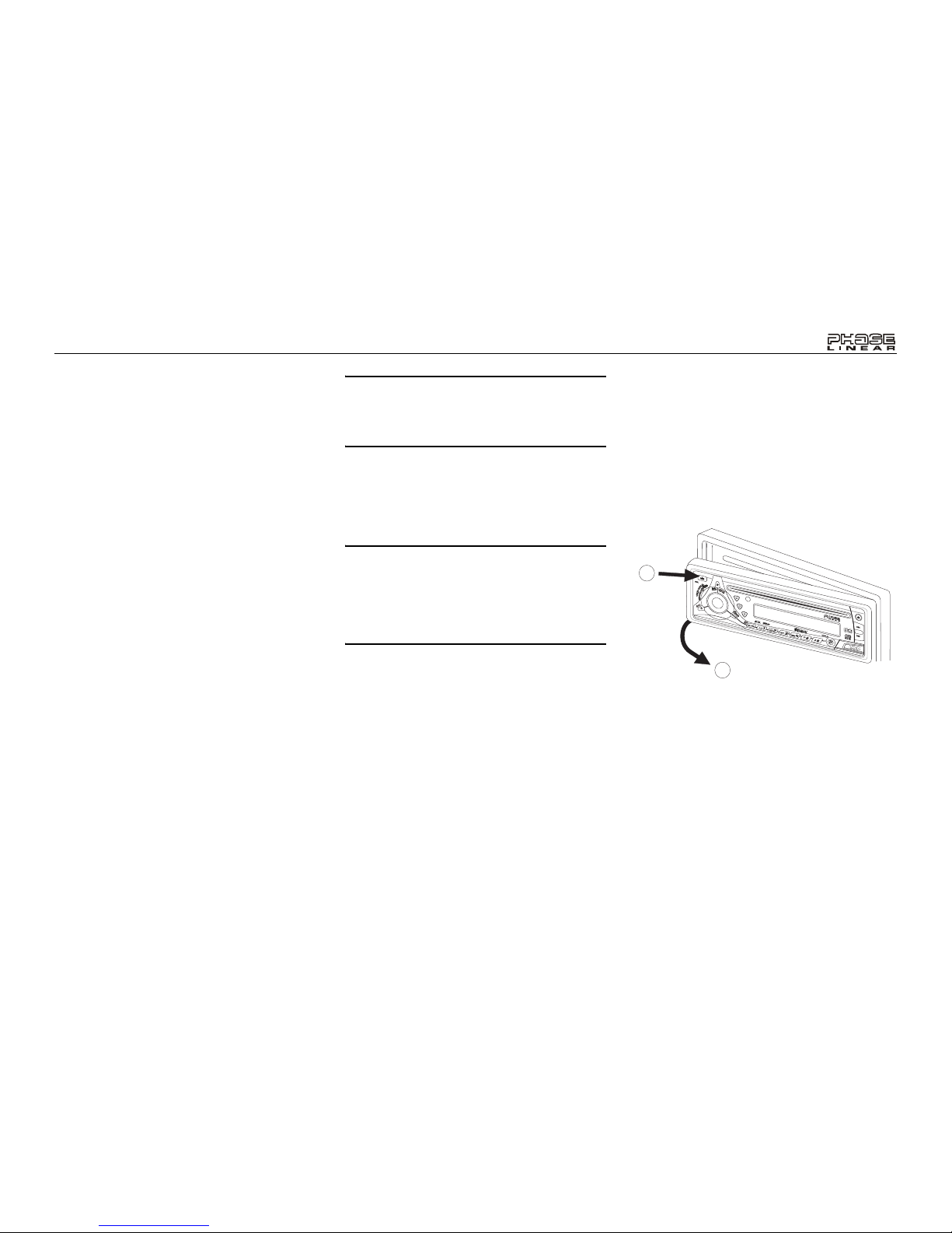
Front Panel Release
The front panel release button (10) releases the
mechanism that holds the front panel to the
chassis.
Detaching the Front Panel
To detach the front panel, first press the front
panel release button (10) to release the left side
of the panel. Next, grasp the released side and
pull it off the chassis. After removing the front
panel, store it in the supplied carrying case to
protect it from dirt and damage.
Re-attaching the Front Panel
To re-attach the front panel, make sure the
electrical terminals on the back of the panel are
free of dust and dirt, as debris could cause
intermittent operation or other malfunctions.
Position the right side of the panel in place so
that it is correctly engaged, then lightly press
the left side of the panel until the mechanism
locks it into place.
1
2
/
TUNE
BASS
SUB
RECORD
BT1611MP3/WMA RECEIVER
MENU
REMOVE FRONT PANEL
BT1611i
10
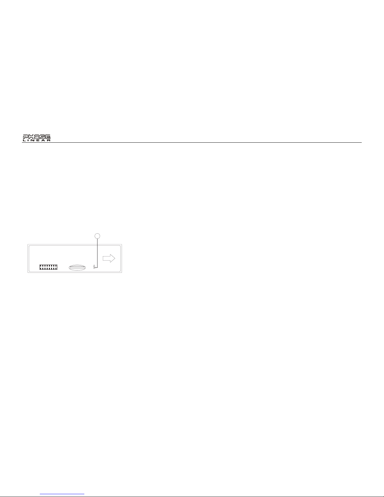
Reset Button
The reset button (11) is located on the front of
the chassis and can only be accessed with the
front panel removed. The reset circuitry
protects the microprocessor circuitry. Since
resetting the unit will erase the time and preset
memories, it should only be activated upon
initial installation after all wiring is complete, or
if there is a malfunction of any of the switches
on the unit. In these circumstances, pressing
the reset button will clear the system and return
the unit to normal operation.
11
RESET
 Loading...