

Audiovox AVXMTGHR9HD Installation And Operation Manual
AVXMTGHR9HD
9"
LCD
Monitor
With
For
and
Rear
Built-In DVD
HDMI/MHL
Player
Port
Seat Entertainment
Installation And Operation Manual
Audiava
f(
\~
I
EEEJ~EEEJ
~
...___
HCrrll~
I
D D D
-
DD
~,_...I-lL~
I I
-
DD
D D D
DDDDDDDDDD
\
--
Jj
-
-
Important
Notices
headrest
Installation
extremely careful
any air bag wiring (usually
Damage to air bag wiring can
any questions regarding wire routing or
Electronics Technical Support at
When connecting power and ground
is
wire
can
so
connection point and the
LCD panel
An
the driver
control, rear
used for
installed
be
when the vehicle's
LCD panel
An
operates when the
installed
to the operator of the motor
of
with seats that have airbags
fused at the point where it is connected to the vehicle ACC
damage to the
result
in
and/or video monitor may be
LCD panel
the
if
side observation
or
television
so that these features
to the rear
reception, video or DVD
parking brake is
or video monitor used for
products
identified by yellow connectors and yellow
result
mobile
or video monitor is used for
vehicle is
the driver's seat where it will
of
vehicle.
requires
personal injury to
in
1-800-225-607
in
vehicle
video product.
navigation. If the LCD panel
or
will only
applied.
gear
in
preparation.
careful
built
installation
4.
mobile
a
if a short circuit
installed
play,
function when the
television
when the parking is not applied must be
or
planning
into them. Keep wiring away from
vehicle
a vehicle, please
in
video
installation, insure that the
develops
a motor vehicle and
in
vehicle
LCD panel
the
reception, video or DVD
not be
and
wire jackets).
occupants.
contact VOXX
wiring.
between the
information, system
or
or video monitor must
vehicle is
visible, directly
Failure to do
video monitor is
you have
If
visible
"park"
in
play
indirectly,
or
Be
ACC
vehicle
to
or
that
Patented:
Refer to www.voxxintl.com/patents
(~T_a_b_le_o_f_C_o_n_te_n_t_s
________________________________
)
Features
Quick
Materials
..............................................................................................................
Start
Guide
............................................................................................
Supplied
..........................................................................................
Headrest Cover Replacement
InstallationInstallationControls
Remote Control
Remote
Control
System S e
DVD Settings
Playing DVDs
Playing
Playing
USB
MP3 Discs
DVD Basics
Vehicle Preparation
Wiring
Diagram
and Indicators Diagram
Battery Replacement
Operation
tt
i n g s a n d Ad j u s t
and
Devices
Adjustments
and
Audio
.............................................................................
................................................................
men
Discs
........................................................................................
......................................................................................................
.....................................................................
..............................................................
......................................................................
............................................................
.................................................
1 0
11
12-15
t s
.........................................................
........................................................
................................................................
1 6
1 7-22
23
23-24
24
25
4
5
6
7
8
9
HDMI/MHL
USB
Devices (Media
Usage
Troubleshooting
Specifications
War r
a n
ty
..........................................................................................................
.................................................................................................
..................................................................................
and
Charging)
.......................................................
26-27
...........................................................................................
28
29
30
3 1 .
3
(~F_e_at_u_re_s
_____________________________________
)
• 9" Digital
Monitor
• Built-in
• Last position
·Five
USB
•
HDMI®/MHL®
•
·On
• Full
Thin
DVD
Audio
DVD
USB
AV
AUX
HDMI/MHL
2.0
Screen
function
/Video
port
Display
Transistor
Film
Player
memory
Source inputs
Input
(OSD)
remote
(TFT)
for DVD Player
control
for
control
Active Matrix Liquid
picture
of
quality
and functions
Crystal Display
(LCD)
CD
DVD,
Plays
•
Channel Wireless
8
•
·Dual
·Adjustable
ChanneiiR
posts and
and MP3 discs
Modulator
FM
Transmitter (for use
tilting
headrest (for adjusting screen viewing angle).
with
optionaiiR
headphones)
4
(Quick Start Guide
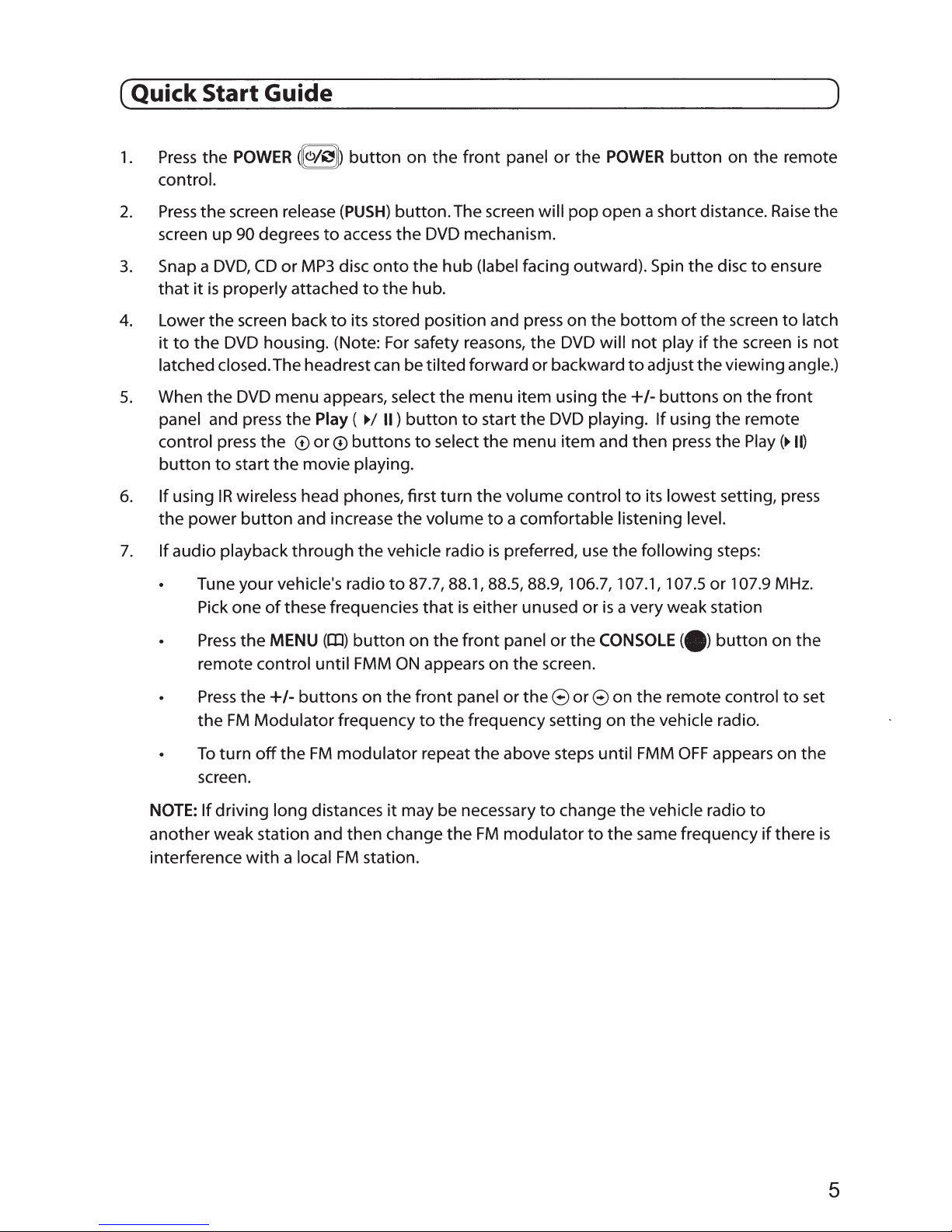
1.
Press
the
POWER
control.
2.
Press
the
screen release
up
screen
3.
Snap a
that
4.
Lower
it
to
latched closed. The headrest
5.
When
panel and press the
control press
button
6.
If
using
the power
90 degrees
DVD,
it
is
properly attached
the
screen back
the
DVD
the
DVD
to
start the movie playing.
IR
wireless head phones, first
button
([e>/")J)
to
CD
or
MP3
housing. (Note: For safety reasons, the
menu appears, select the menu item using the +I-buttons on the
Play
the
CD
or
and increase the volume
button
(PUSH)
access
disc
to
its stored position and press on the
(
CD
buttons
on the
button. The screen will
the
onto
the
to
the
hub.
can
be tilted forward or backward
~I
II)
button
to
front
panel or the
DVD
mechanism.
hub
(label facing outward). Spin the disc
to
start the
select the menu item and then press the
turn
the volume control
to
a comfortable listening level.
pop
DVD
DVD
POWER
open a short distance.
bottom
will
playing.
button
not
play
to
adjust the viewing angle.)
If
using the remote
to
its lowest setting, press
on the remote
of
the screen
if
the screen
to
Play
Raise
ensure
front
)
the
to
latch
is
not
(~II)
7.
If
audio playback
Tune your vehicle's radio
Pick one
Press
the
remote control until
Press
the
the
FM
To
turn
screen.
NOTE:
another weak station and then change the
interference
If
driving long distances
through
of
these frequencies
MENU (rlJ)
button
FMM
+/- buttons on the
Modulator
off
the
with
a local
frequency
FM
modulator repeat the above steps until
FM
the vehicle radio
to
ON
it
may be necessary
station.
is
preferred,
87.7, 88.1, 88.5, 88.9, 1 06.7, 107.1, 107.5 or 107.9 MHz.
that
is
either unused or
on the
front
front
panel or the
appears on the screen.
panel or the 8 or 8 on the remote control
to
the frequency setting on
FM
modulator
to
change
use
the following steps:
is
a very weak station
CONSOLE
the
the
to
the same frequency
(.)
vehicle radio.
FMM
OFF
vehicle radio
button
appears on the
on the
to
if
to
set
there
is
5
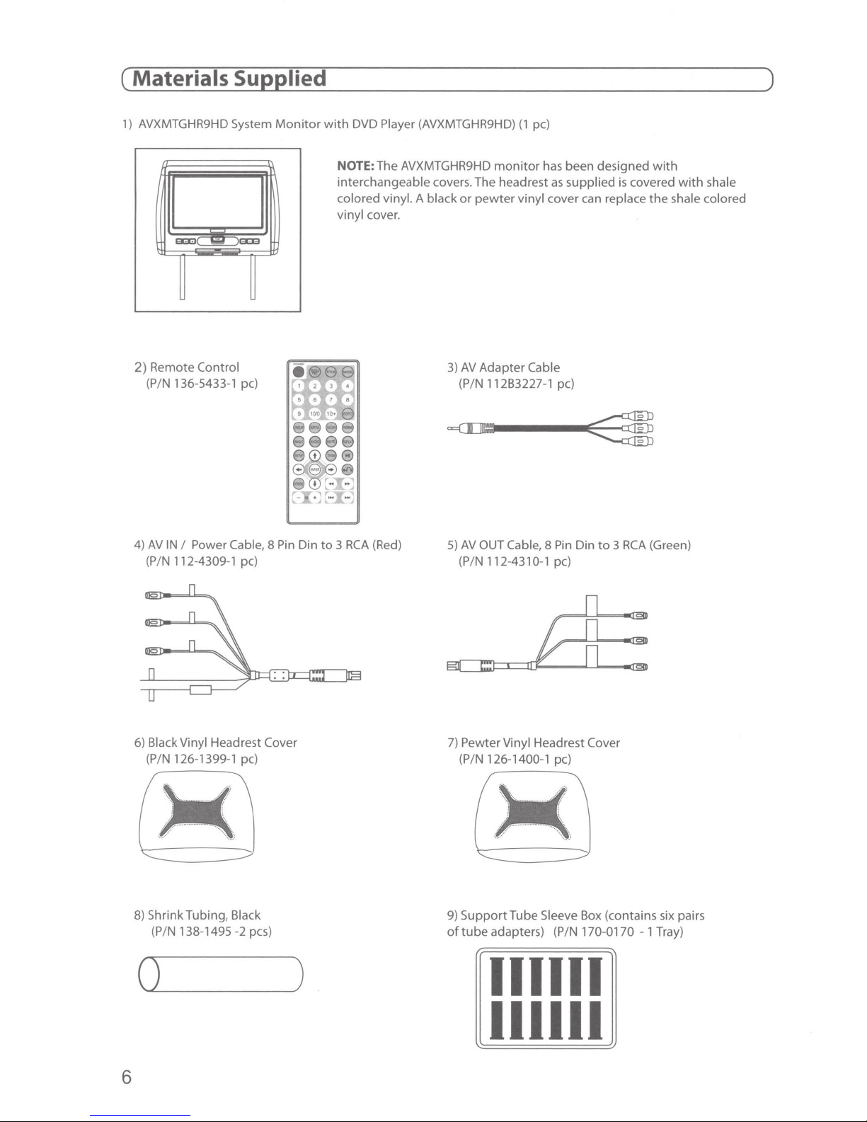
(~M_a_t_e_r_ia_ls_S_u~P~P~I_ie_d
1)
AVXMTGHR9HD System
Monitor
______________________________
with
DVD Player (AVXMTGHR9HD)
(1
pc)
~)
EIIOIOJ(
~
2) Remote Control
(P/N 136-5433-1 pc)
4)
AV
IN I Power Cable, 8 Pin
(P/N 112-4309-1 pc)
B:lil
NOTE: The AVXMTGHR9HD
interchangeable covers. The headrest
colored vinyl. A black
vinyl cover.
Din
to 3 RCA
(Red)
or
3)
AV
(P/N 112B3227-1 pc)
5)
AV
(PIN 112-4310-1 pc)
monitor
pewter
Adapter
OUT Cable, 8 Pin Din
has been designed
as
supplied
vinyl cover can replace
Cable
is
covered
to 3 RCA
with
with
the
shale colored
(Green)
shale
6)
Black Vinyl Headrest Cover
(P/N 126-1399-1 pc)
8)
Shrink Tubing, Black
138-1495-2
(P/N
0
_________
pes)
6
)
7)
Pewter Vinyl Headrest Cover
(P
/N
126-1400-1 pc)
9)
SupportTube
of
tube
adapters) (PIN 170-0170 - 1 Tray)
Sleeve Box (contains six pairs
111111
111111
(~H_e_a_d_r_e_st_C_o_v_e_r_R_e~p~l_a_ce_m
__
e_n_t
_________________________
)
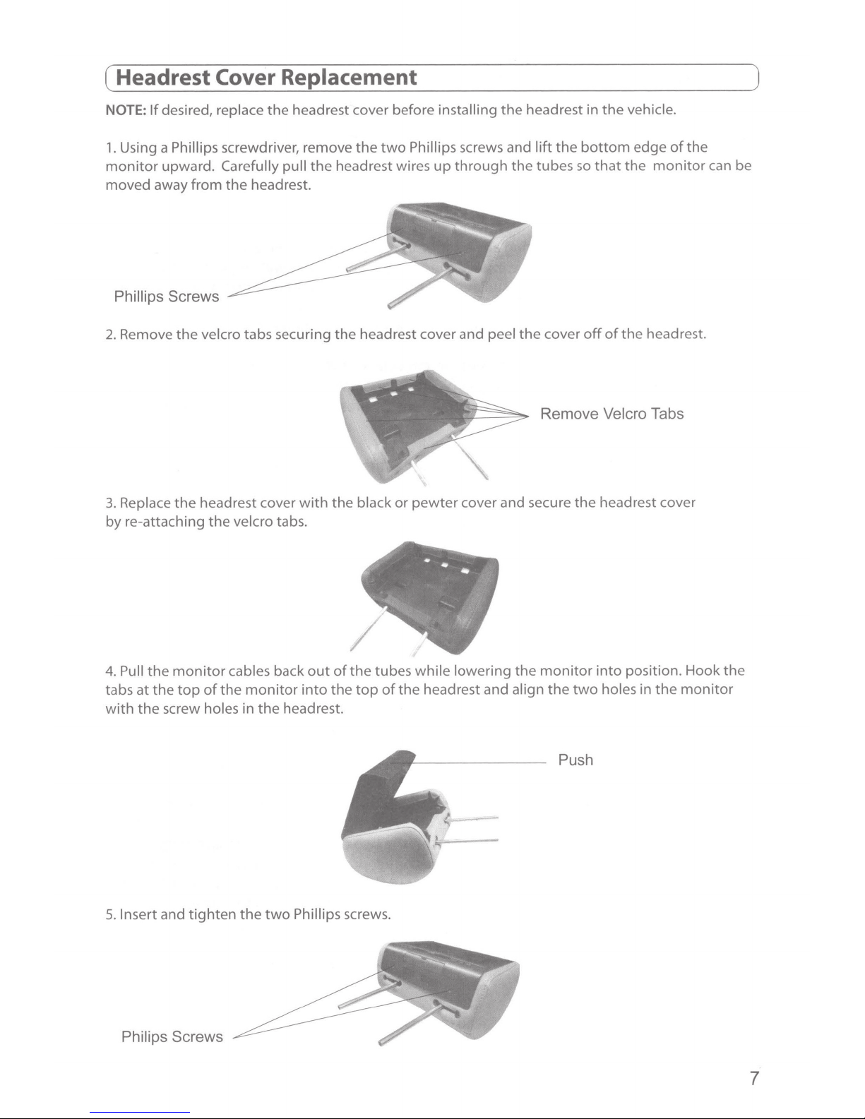
NOTE:
1.
monitor
moved away from
If
desired, replace the headrest cover before installing
Using a Phillips screwdriver, remove the
upward. Carefully pull
the
headrest.
the
headrest wires up through the tubes
Phillips Screws
2.
Remove the velcro tabs securing
3.
Replace
by
re-attaching the velcro tabs.
the
headrest cover
with
the
the
the
headrest in
two
Phillips screws and lift
headrest cover and peel the cover
the
Remove Velcro Tabs
black or pewter cover and secure
the
vehicle.
bottom
so
off
the
edge
that
the
of
the
headrest cover
of
the
monitor
headrest.
can
be
4.
Pull
the
monitor
at
the
top
of
tabs
with
the
screw holes in
5.
Insert and tighten the
the
Philips Screws
cables back
monitor
the
headrest.
two
Phillips screws.
out
into
of
the
the
tubes while lowering the
top
of
the
headrest and align the
monitor
two
Push
into position. Hook the
holes in
the
monitor
7
(~l_n_st_a_ll_at_i_o_n_-_V_e_h_ic_le_P_r_e~p_a_ra_t_io_n
1.
Decide on the system configuration and the options
2.
Read
the manual and
3.
Decide on the
connected
4.
Prepare the vehicle by removing any interior
wiring
manual will only focus on the installation
configuration.
NOTE:
5.
Locate
ignition key
ignition key
switch or fuse box.
as
The
an
mounting
to
the
well
as
monitor
accessory power source and ground
is
in the accessory and run positions and 0
is
in the
get
familiar
locations and methods
AVXMTGHR9HD
all
areas
where interconnecting wire harnesses will be located. This
should be installed in the passenger position most used.
OFF
position. Generally, these wires
with
system.
____________________
that
will be installed.
the electrical requirements and connections.
of
of
mounting
trim
necessary
the
AVXMTGHR9HD
with + 12
VDC
the products
to
gain
access
monitor
VDC
(ACC)
present when the
should be present when the
can
be found at the ignition
that
to
the vehicle's
in the supplied
will be
~)
NOTE:
vehicle wiring damage.
6.
Run
Diagrams on page
routed in such a manner
leave enough slack in the wiring at each
Be
down, and for seat movement.
7.
Install the headrest:
a.
b.
headrest by pulling the posts apart or pushing them together. (Note: grab the posts close
to
c.
vehicle headrest post.
d.lnsert
needed).
e.
guides. Make sure
f.
cables
the headrest
Insure
the wiring harnesses
sure
Remove vehicle's original headrest.
Adjust the posts
the
bottom
Locate
Hold the headrest above the seat and insert the
Route the cables through the seat back and
to
that
the
accessory power
throughout
9).
Be
sure
that
that
it
to
leave enough slack in the
of
the
AVXMTGHR9HD
of
the headrest while doing this adjustment)
the
tube adapters
the appropriate support
that
remove the slack.
to
move up or down.
that
the headrest
Be
is
fused at the source. Failure
the vehicle
all the wiring
will
not
be pinched when
component
monitor
most closely match the outer diameter
tube
adapters in vehicle headrest post guides (if
is
in the correct position (display facing the rear).
sure
to
leave enough slack in the
cables
to
the same
out
to
do
so
as
necessary (Refer
is
protected from sharp edges and
it
is
fully installed.
to
allow sufficient working room.
to
allow the headrest
two
the
width
bottom
cables
of
into
of
to
the Wiring
Be
to
move up or
the posts on the original
of
the original
the vehicle support
the seat while pulling the
monitor
cables
may result in
sure
to
is
to
allow
8.
Connect all the components
system functions.
9.
If
two
(2)
AVXMTGHR9HD's
unit
to
IRTB.
See
page
8
together
are installed in a vehicle, set one
16
or page
(electrically) and verify proper operation
18
for instructions.
unit
to
IRTA
and the other
of
all the
(~l_n_st_a_ll_at_i_o_n_-_W_i_ri_n~g_D_i_ag~ra_m
________________________
~)
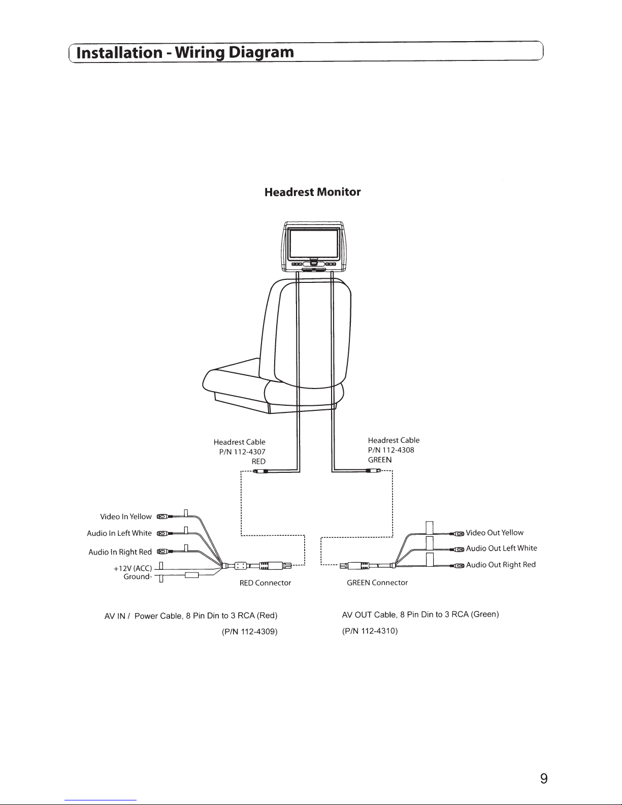
Headrest Monitor
+12V(ACC)
Ground-
I
IN
AV
Power
--.-.-----l
Cable,
8 Pin Din
Headrest
112-4307
P/N
RCA
3
to
(P/N
Cable
RED
Connector
RED
(Red)
112-4309)
GREEN
OUT
AV
(P/N
Headrest
112-4308
P/N
GREEN
Connector
Cable,
112-4310)
Cable
to
3
RCA
Video Out Yellow
Left White
Out
Audio
Right
Out
Audio
(Green)
~....L,~=-IlED
~==L...lc=.=--llEIJ
Pin Din
8
Red
9
(~C_o_n_t_ro_l_s_a_n_d_l_n_d_ic_a_t_o_rs_D
__
ia~g~r_a_m
____________________
~)
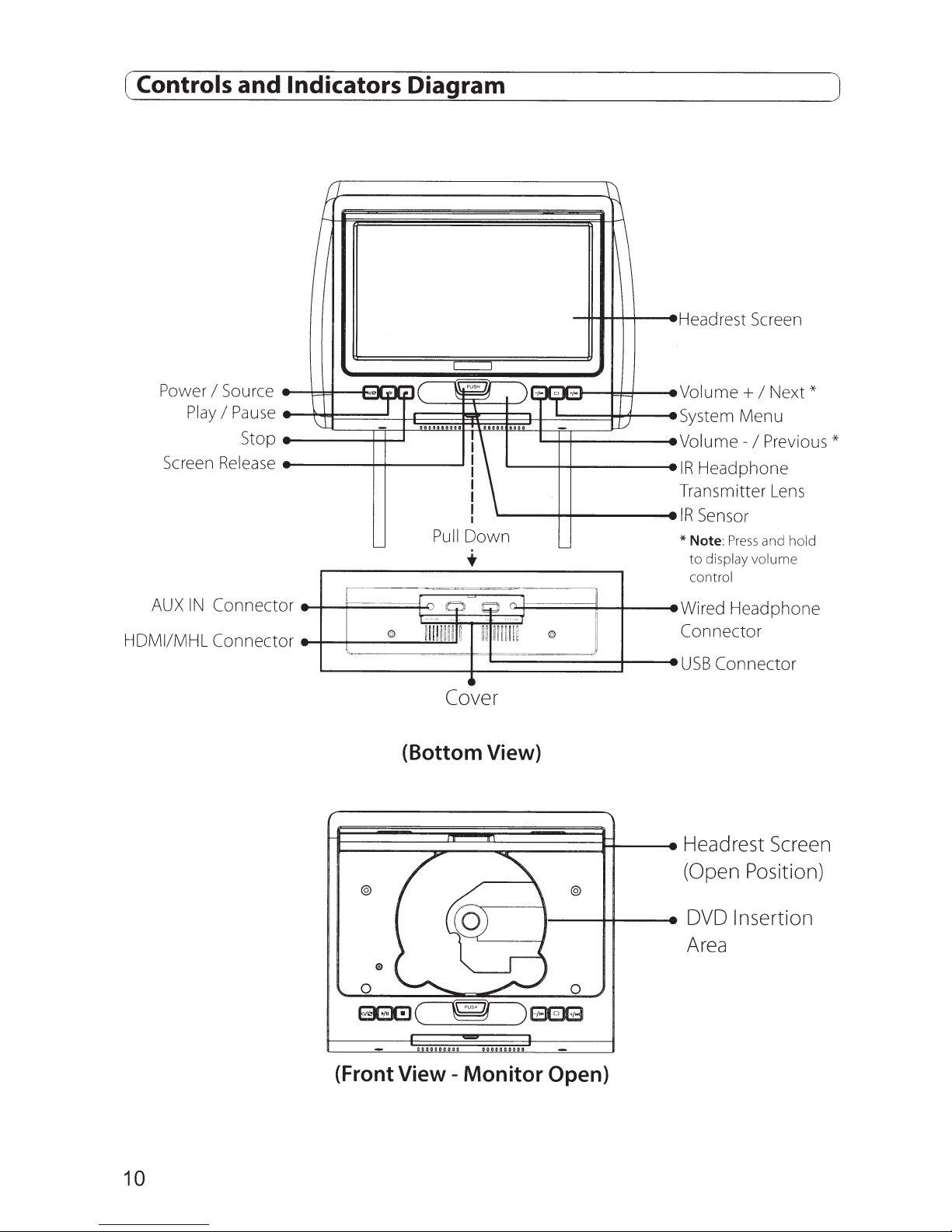
Stop
-
-
-
-
-
-
-
-
Power
AUX
HDMIIMHL Connector
Play
Screen
IN
I
Source
I
Pause
Release
Connector
-
H
I
1--
\.
\:
...........
L__
~
-
-
-----f
!
@
I
~
L__
C==:J
,
~c
~~
...
...
Pull
-"
Q
--·
--
-
--
mmm~
Cover
) I
\
aaaaa
aaao
1\
I
Down
tiJ
n.
li
llliili
-
0
1
..
1
1
~
1--
--.
o
@
-.
.,
..
-
'---
--- J
)\
~
[)
J
-
Headrest
--
-
Volume+
System
Volume-
I
R
Head
-
Transmitter
-
IR
Sensor
*Note
to
con trol
Wired Headphone
-
Connector
USB
Screen
I
Menu
I
Previous*
phone
:
Press
and
display
volume
Connector
Next*
Lens
hold
10
(Bottom View)
E~~~~~~~~~3=~---
@
@
•---1-i----e
Headrest
(Open
DVD
Position)
Insertion
Screen
Area
0 0
EJGX!J~EEE
(Front
View-
Monitor
Open)
(~R_e_m_o_t_e_C_o_n_t_ro_I_B_a_tt_e_r~y_R_e~p_la_c_e_m_e_n_t
________________
~)
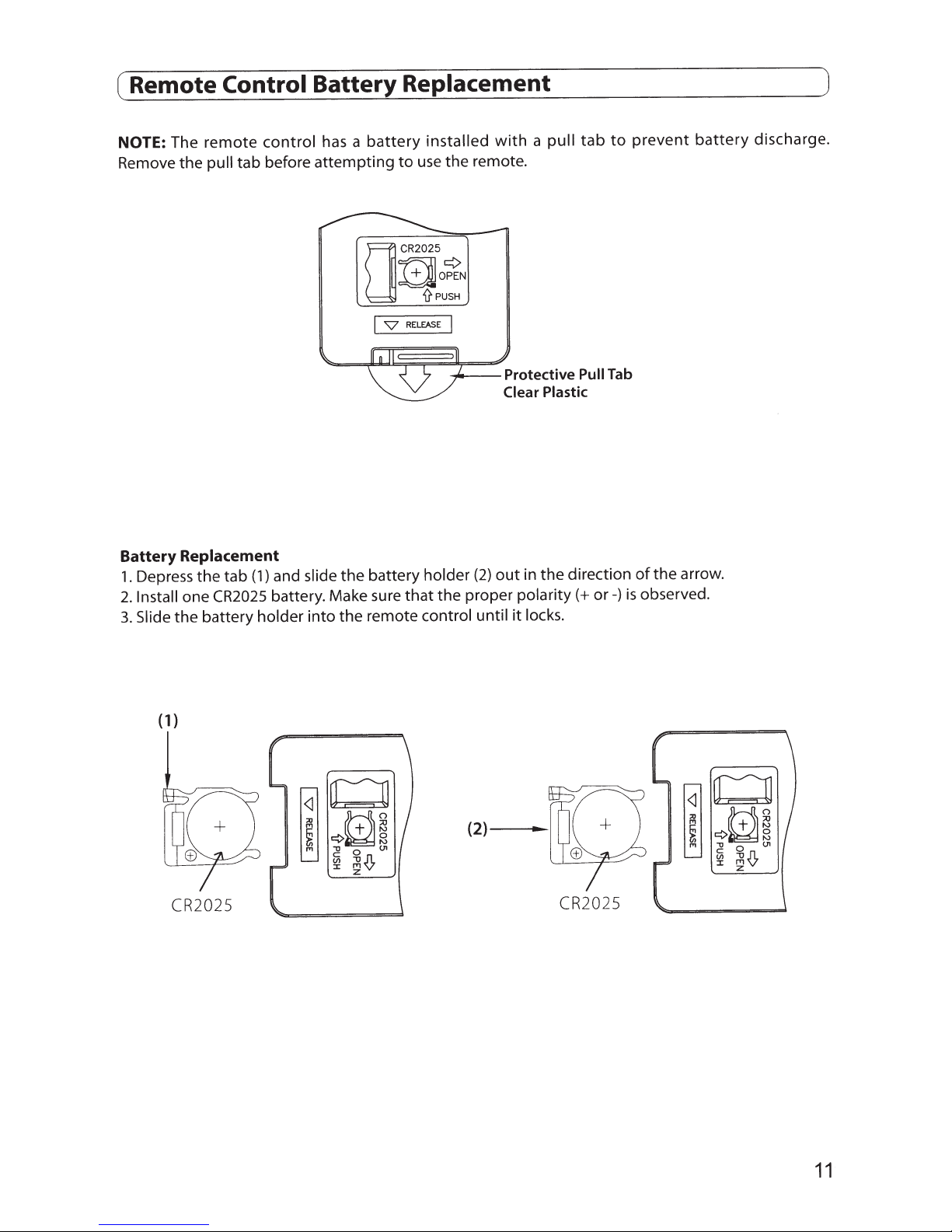
NOTE: The
Remove
Battery
1.
2.
3.
the
Replacement
Depress
one
Install
the
Slide
tab
tab
control
before
and slide
(1)
battery. Make sure
remote
pull
the
CR2025
battery holder
battery
has a
attempting
battery holder
the
remote control until
the
into
I
v
use
to
RELEASE
that
a
installed
the
with
remote.
I
~--Protective
Plastic
Clear
the
in
out
(2)
the
proper
polarity(+
locks.
it
tab
pull
Pull
direction
to
Tab
or-)
prevent
the
of
observed.
is
battery
arrow.
discharge.
( 1)
CR2025
CR2025
11
 Loading...