

Page 1

INSTALLATION GUIDE FOR THE:
GM Data Bus
Door Trigger Interface
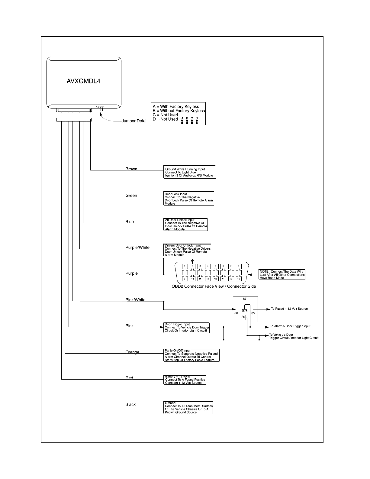
AVXGMDL4
With Door Locking
The AVXGMDL4 Interface module connects to the Class II Data Bus wire, On-Board Diagnostics ll (OBD2), of the
vehicle and detects the vehicle’s door condition (open or close), provide door lock/unlock information as well as
arm/disarm for those vehicles with factory alarm systems. This device is used on Chevrolet/GMC & Cadillac.
Sierra, Yukon, Denali, Light and Medium Duty Pickups, Suburban, Tahoe, CK Series, Escalade, and Hummer H2.
Because these vehicles use the on board data bus instead of a common door trigger wire typical installation
would include the removal of door panels to connect the latch wires of each door.
The AVXGMDL4 allows you to, pick up the door open close status of the vehicle as well as provide door lock
unlock signals when required. Simply connect to the alarms negative door trigger input wire, negative door lock
unlock wires, connect + 12 volts, ground, and one wire to the vehicle’s data bus and your done. No additional
labor is required to remove panels or run trigger wires throughout the vehicle for door locks and door triggers.
This module when receiving RF command from Audiovox alarm will provide door lock/arm, door unlock drivers &
disarm & or door unlock all disarm.
Wiring The Module:
NOTE: All wires must be verified prior to connection. If you are uncertain of a wire’s function found in
the Data Link Connector , (DLC), consult the shop manual or call Audiovox T echnical Service.
One Side Of Interface:
Brown: Ground While Running
Connect to Light Blue Ignition 3 W ire of the Audiovox Remote Start Unit. This wire prevents the alarm from
triggering if the interior light turns on while running under control of the remote start. Most Audiovox remote start
units have a shunt circuit to prevent triggering so this wire may not be needed, however earlier remote start units
or competitors models may not offer this feature.
Green: Door Lock Input
Connect to the all door ground pulse lock output wire of your alarm or keyless entry system.
Blue: All Door Unlock Input
Connect to the all door ground pulse unlock output wire of your alarm or keyless entry system.
Purple/White: Drivers Door Unlock (See Note Below)
Connect to the drivers door ground pulse unlock output wire of your alarm or keyless entry system.
Purple: Data Line Output (See Exploded View On Diagram Page)
Connect to the data wire pin #2 located in the 16 pin OBD2 connector in the vehicle.
NOTE: This wire must be connected last after all other connections have been made.
Pink/White: Alarm Trigger Bypass Output 350 mA For Dome Light Control (See Diagram)
Pink: Interior Light Sense Input
Orange: Ground Input To Activate/Deactivate Factory Panic
Connect this input to a separate ground output of your alarm or keyless entry system if you want to control the
factory panic feature independent of the aftermarket alarm or keyless entry.
Red: + 12 Volts
Connect this wire to the + 12 volt constant wire found in the DLC. Typical vehicle color is Orange.
Black: Chassis Ground
Connect this wire to a clean unpainted metal surface in the vehicle or a preexisting chassis ground wire. Typical
vehicle color found in the DLC is Black, or Black/White.
NOTE: If the vehicle does not offer separate drivers door/all door unlock feature or if the customer does not want
sperate control of driver/all doors. Connect Blue of the interface to the green door unlock 1 wir e of the Audiovox
Alarm. If the Audiovox Alarm you are using does not have 3 pin door lock/unlock connector then the feature is
not available and you must wire the Blue of the interface to the green - door unlock wire of the Audiovox Alarm
System.
Once all wires have been connected, turn the ignition on. You will hear three chirps confirming the unit is initialized
and will now operate from your alarm’s remote.
Page 2
1286571
 Loading...