

Audiovox AMP-591A Owner's Manual

Owner'sOwner's
Owner'sOwner's
Owner's
ManualManual
ManualManual
Manual
ModelAMP-591A
300WattStereoAmplifier

INDEX
Specifications .............................................................................1
Precautions ................................................................................2
Installation Instructions ..............................................................3
Wiring Instructions ................................................................4 - 5
Stereo and Mixed-Mono Input Wiring Diagram .........................6
Stereo and Mixed-Mono Output Wiring Diagram ......................7
Mono (Bridged) Input Wiring Diagram ...................................... 8
Mono (Bridged) Output Wiring Diagram ................................... 9
Operation ..........................................................................10 - 12
Warranty ..................................................................................13

HIGH PERFORMANCE STEREO AMPLIFIER
This power amplifier has been designed to provide high quality performance with
a minimum of maintenance. However, it's performance will only be as good as the
care and quality of components with which it is installed. We therefore advise that
you read these instructions very carefully to familiarize yourself with the product and
it's features.
Should you require assistance with the installation or wiring of this unit, please call
our toll-free "HELP" line at 1-800-645-4994 during the days/hours shown.
Monday- Friday
Saturday
8:30am- 7:00pm Eastern
9:00am- 5:00pm Eastern
1-800-645-4994
HELP!
SPECIFICATIONS
-1-
* Due to continuing improvement, Audiovox reserves the right to change features and design without notice.
Maximum Output Power
Stereo Operation: 150 watts x 2
Mono Operation: 300 watts x 1
Output Power @ 1% T.H.D.
Stereo Operation: 100 watts RMS x 2
Mono Operation: 200 watts RMS x 1
Output Impedance: 2 - 8 ohms (stereo)
4 - 8 ohms (mono)
Frequency Response: 10 - 50,000 Hz. ± 1 dB
Channel Separation: 50 dB
Signal / Noise Ratio: 80 dB (A-Weighted)
Input Impedance: low-level 10K ohms
high-level 100 ohms
Input Sensitivity: low-level 200 mv. - 2 v.
high-level 2 - 10 v.
Filter Types: low-pass & high-pass
Filter Slope: 12 dB/octave
Filter Crossover: Low-pass: 30 - 120 Hz. (selectable)
High-pass: 120 - 800 Hz. (selectable)
Bass Boost: +10 dB @ 50 Hz.
Supply Voltage: 12 volts, negative ground
Fuse Rating: 20 amps.
Dimensions (W x H x D): 9" x 2-1/4" x 10-5/8"
230 mm x 57 mm x 270 mm

PRECAUTIONS
1. Although this unit is designed with built-in self-protection circuits, there may be a possibility of damage if it is not wired
correctly. Please follow the wiring instructions carefully for the type of system being used.
2. The last lead to be connected is the wire to the positive (+) terminal of the battery. Connect this wire only after having
completed and checked all other connections to the amplifier.
3. By nature of its design, a power amplifier generates heat and requires good air circulation around it to dissipate that
heat. Do not install the amplifier in an enclosed area which does not permit adequate air circulation. Should the
temperature of the unit rise too high, the internal thermal sensors will shut off operation until it has cooled down
sufficiently.
4. If fuse replacement is necessary, use only fuses of the same ampere rating as originally supplied with the unit. The
use of fuses with incorrect ratings may cause serious damage to the amplifier. If fuses blow consistently, carefully
check all electrical connections to the unit.
5. Supply of adequate battery voltage is critical to the proper operation of the power amplifier. The leads to the battery
and chassis ground must be of a thick enough gauge to provide this voltage to the amplifier. We recommend
#16 gauge wire or thicker (smaller gauge #) for the battery and ground leads.
6. Make certain that the speaker(s) to be used with this amplifier are capable of handling the output power (wattage)
of the unit. Use of speaker(s) not rated for the output of this amplifier may cause damage to or failure of the
speaker(s) for which Audiovox will not be liable.
-2-
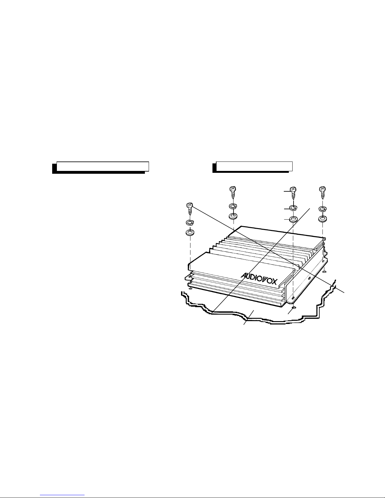
INSTALLATION INSTRUCTIONS
INSTALLATION DIAGRAM
1. Select a mounting area where the amplifier will
have sufficient air circulation for proper cooling.
Inadequate air circulation will cause the temperature
of the amplifier to rise and will trigger the
thermal protection mode.
2. Place the amplifier on the mounting surface
and mark the locations of the four mounting
holes as shown in the illustration.
3. Remove the amplifier and drill a 1/8" hole a t
each of the four locations.
CAUTION: Before drilling the holes, look at the
underside of the mounting surface. Always
check carefully to avoid drilling into wiring,
braces, fuel or brake lines. CHECK BEFORE
YOU DRILL !
4. Secure the amplifier to the mounting surface
using the self-tapping screws provided.
MOUNTINGSURFACE
1/8"DIA. HOLE
SELF-TAPPINGSCREW
SPLITWASHER
FLATWASHER
-3-
 Loading...