

Page 1
AUDIOVOX
OPERATOR’S GUIDE
AFX-35.00
INTEGRATED PERSONAL FACSIMILE
Please read this Operator’s Guide carefully before using your new AFX-2500.
This Guide contains instructions for proper setup,
operation and maintenance of
your AFX-2500
Page 2

Q
The following information is applicable only to
AFX-2500 facsimile machine installed in United
States.
Label Identification
This equipment complies with Part 68 of the FCC
rules. On the bottom of this equipment is a label
that contains, among other information, the FCC
registration Number and Ringer Equivalence
Number (REN) for this equipment. You may need to
provide this information to your telephone company.
Type of Service
Model AFX-2500 is designed to be used on
standard device telephone lines. Connection to
telephone company-provided coin service (central
office implemented systems) is prohibited.
Connection to party-line service is subject to state
tariffs.
Telephone Company Procedures
The goal of the telephone company is to provide
you with the best service it can. In order to do this,
it may occasionally be necessary for it to make
changes in its equipment, operation, or procedures.
If these changes affect your service or the operation
of the equipment, the telephone company will give
you notice, in writing, to allow you to make any
changes necessary to maintain uninterrupted
service.
If you have any questions about
your telephone
line, such as how many pieces of equipment you
can connect to it, the telephone company will
provide this information upon request.
In certain circumstances, it may be necessary for
the telephone company to request information from
you concerning the equipment which you have
connected to your telephone line. Upon request of
the telephone company, provide the FCC
registration number and the Ringer Equivalence
Number (REN) of the equipment which is
connected to your line; both of these items are
listed on the equipment label and in the Service
Information chapter of this guide. The sum of all of
the
RENs
on your telephone line should be less
than five in order to assure proper service from the
telephone company. In some cases, a sum of five
may not be usable on a given line.
About interference
This equipment has been tested and found to
comply with the limits for a Class B digital device,
pursuant to Part 15 of the FCC Rules.
1
These limits are designed to provide reasonable
protection against harmful interference in a
residential installation. This equipment generates,
uses, and can radiate radio frequency energy and,
if not installed and used in accordance with the
instructions, may cause harmful interference to
radio communications. However, there is no
guarantee that interference will not occur in a
particular installation. If this equipment does cause
harmful interference to radio or television reception,
which can be determined by turning the equipment
off and on, the user is encouraged
to try
to correct
the interference by one or more of the following
measures:
Reorient or relocate the receiving antenna.
Increase the separation between the equipment
and the receiver.
Increase the seperation between the eqipment
and the receiver.
Connect the equipment into an outlet on a circuit
different from that to which the receiver is
connected.
Consult the dealer or an experienced radio/TV
technician for help.
If a Problem Arises
If any of your telephone equipment is not operating
properly, you should immediately remove it from
your telephone line, as it may cause harm to the
telephone
network
If the telephone company notes
a problem, it may temporarily discontinue service.
When practical, the telephone company will notify
you in advance of the disconnection. If advance
note is not feasible, you will be notified as soon as
possible. When you are notified, you will be given
the opportunity to correct the problem and informed
of your right to file a complaint with the FCC.
Hearing Aid Compatible
The telephone handset attached to the facsimile is
hearing aid compatible.
Lightning
Your unit has built-in protection circuits, which meet
or exceed FCC requirements, to reduce the risk of
damage from surges in telephone line currents.
However, lightning striking near or on these lines
can cause an exessive surge of voltage that can
damage the phone.
Lightning damage is uncommon. However, if you
are concerned about it or live in an area with
frequent and/or severe electrical storms, we
suggest that you unplug your electronic equipment
during the storms.
Page 3

DOC Information
Q
The following information is applicable only to
AFX-2500 facsimile machine installed in
Canada.
Notices
The Canadian Department of Communications
(DOC) label identifies certified equipment. This
certification means that the equipment meets
certain telecommunications network protective,
operational and safety requirements. The
Department does not guarantee the equipment wil
operate to the user’s satisfaction.
Before installing this equipment, users should
ensure that it is permissible to be connected to the
facilities of the local telecommunications company.
The equipment must also be installed using an
acceptable method of connection. In some cases,
the company’s inside wiring associated with a
single line individual service may be extended by
means of a certified connector assembly (telephone
extension cord). The customer should be aware
that compliance with the above conditions may not
prevent degradation of service in some situations.
Repairs to certified equipment should be made by
an authorized Canadian maintenance facility
designated by the supplier. Any repairs or
alterations made by the user to this equipment, or
equipment malfunctions, may give the
telecomm-
unications company cause to request the user to
disconnect the equipment.
Users should ensure for their own protection that
the electrical ground connections of power utility,
telephone lines and internal
metalic
water pipe
system, if present, are connected together. This
precaution may be particularly important in rural
areas.
Caution
Users should not attempt to make such connections
themselves, but should contact the appropriate
electric inspection authority, or electrician, as
appropriate. The Load Number (LN) assigned to
each terminal device denotes the percentage of the
total load to be connected to a telephone loop
which is used by the device, to prevent overloading.
The termination on a loop may consist of any
combination of devices subject only to the
requirement that the total of the load numbers of all
the devices does not exceed
100.
The Load Number of this unit
is
#8
Class B
This Digital Apparatus does not exceed the Class B
limits for Radio Frequency noise from Digital
Apparatus set out in the Radio Interference
Regulations of the Canadian Department of
Communications.
Page 4
Renseianements du
Minis&e
des Communications
Les renseignements suivants ne s’appliquent
qu’aux
tekopieurs install&
au Canada.
Avis
L’etiquette
du
Ministere
des Communications
(DOC) est une marque d’identification d’appareil
certifie. Cette certification signifie que I’appareil
repond a
certains
criteres
de
securite
et
d’utiiisation. Cependant, le
Ministere ne
peut pas
garantir que I’appareil rencontrera
les
exigences de
son utilisateur.
Avant de faire I’installation de I’appareil, I’utilisateur
devrait s’assurer qu’il pourra brancher son appareil
en utilisant
les
services generalement offer& par la
compagnie
telephonique
de sa region. II faut
s’assurer de brancher convenablement I’appareil.
Dans certains cas,
le
systeme interne de
communication d’une compagnie
possede
aussi
une
ligne
individuelle qu’il vous sera possible
d’utiliser avec un dispositif d’assemblage certifie
(rallonga de telephone). L’utilisateur devrait se
renseigner
afin
de faire une bonne utilisation de son
appareil et de ne pas nuire au systeme interne de
communication de la compagnie.
Toute reparation d’un appareil certifie devrait
Btre
effectuee dans un centre d’entretien approuve par
le
fournisseur. Toute reparation ou modification
apportee
par I’utilisateur B son appareil ou tout
probleme de fonctionnement pourrait forcer votre
compagnie
telephonique a debrancher
votre
appareil.
L’utilisateur devrait s’assurer que les raccordements
de mise
a
la terre de I’alimentation, des
lignes
telephoniques
et du systeme de tuyauterie
hydraulique, si present, soient
tous
relies
ensembles. Cette
mesure
de
securite
est
importante surtout en milieu rural.
Mise en garde
:
L’utilisateur ne devrait pas essayer
de faire de tels raccordements
seul, il
devrait faire
appel a du personnel
qualifie
ou a un electricien
selon le cas.
Le numero de raccordement (LN) se ‘rapporte
&
chaque appareil et determine le nombre maximum
de raccordements afin d’eviter une surcharge. La
boucle peut comprendre plusieurs choix diff
drents
tant et aussi longtemps que le total des numhros de
raccordement ne dhpasse pas la somme de 100.
Le
numero
de raccordement de votre appareil est
:
#8
Classe
B
Cet appareil
n’exckde pas
les
limites de la classe
8
pour
les
Omissions de parasites radio a partir d’un
appareil
numerique etablies par le reglement sur
les
parasites radio du
Ministhe
des Communications.
3
Page 5
About This Guide
Congratulations
!
Your facsimile is a compact electronic
facsimile
(fax)
machine that uses advanced telephone
and
computerized image-sending technology to
send
copies of your important documents anywhere ir
the world.
Your fax is easy to set up and use, but you
should
read this guide and follow the setup and
operation
steps carefully to ensure that your fax
operate:
correctly, and to take advantage of its powerfl
features.
T
Important
\
Please
be sure to read and perform the steps
listed in Setting Up. These steps are necessary
before you can begin to use your unit.
Once you become familiar with the basic
operation of your AFX-2500, find the Quick
Reference Guide included with this guide and
keep it near your machine. That will serve as an
easy reminder of how to send and
receive
during day-today faxing with your fax machine.
Contents
A Quick Look at
Your Machine
. . . . . . . . . . . . . . . . . . . . . . . . . . . .
5
Front View, Rear View, Side View, Control
Panel
Setting Up
. . . . . . . . . . . . . . . . . . . . . . . . . . . . . . . . . . . . . . . . . . . . . . . . . . . . . . . . . . . . . . . . . . . . . . .
7
Assembling & Connecting
. . . . . . . . . . . . . . . . . . . . . . . . . . . . . . . . . . . . . .
a
Installing the Handset, Attaching the
Document Tray, Connecting the Phone Line,
Connecting Extension Telephone or
Answering Machine, Connecting the Power,
Turning the Power On, Choosing Dial Mode,
Setting Speaker Volume, Setting Ringer
Volume
Loading Fax Paper
. . . . . . . . . . . . . . . . . . . . . . . . . . . . . . . . . . . . . . . . . . . . . . . . . . . . .
1
Setting Up Basic Information
.
. . . . . . . . . . . . .. . . .. . . . .. . . . . . . . . . . . .
.
n
I
S
II
4
Receiving
14
. . . . . . . . . . . . . . . . . . . . . . . . . . . . . . . . . . . . . . . . . . . . . . . . . . . . . . . . . . . . . . . . . . . . . . . .
AUTO RCV. Mode, TEL Mode,
ANS/FAX
Mode, Voice Request
Important Receiving Facts
. . . . . . . . . . . . . . . . . . . . . . . . . . . . . . . . . . . . .
17
Voice Request, Clearing Paper Jams, Fax
Paper Storage
Sending
. . . . . . . . . . . . . . . . . . . . . . . . . . . . . . . . . . . . . . . . . . . . . . . . . . . . . . . . . . . . . . . . . . . . . . . . . . .
19
Important Sending Facts
. . . . . . . . . . . . . . . . . . . . . . . . . . . . . . . . . . . . . . . . .
20
Memory Dialing,
Automatic redialing,
Handset Up and Down, Clearing Document
Jams, Voice Request, Confirmation Report,
Preparing a Good Original, Page
&
document Size Limitation, Setting the
Resolution, Making Copies
Controlling Transmission Quality
.........._..........
23
Storing Speed Dial Numbers
. . . . . . . . . . . . . . . . . . . . . . . . . . . . . . .
24
Setting User Options
25
. . . . . . . . . . . . . . . . . . . . . . . . . . . . . . . . . . . . . . . . . . . . . . . .
Printing Reports
. . . . . . . . . . . . . . . . . . . . . . . . . . . . . . . . . . . . . . . . . . . . . . . . . . . . . . . . . .
26
Confirmation Report, Location Number List,
Options List, Transmission Report,
Reception Report
Maintenance
and
Troubleshooting
. . . . . . . . . . . . . . . . . . . .
28
Troubleshooting
Guide, Cleaning
Components, How a Fax Works, About
Facsimile Compatibility
Specifications
. . . . . . . . . . . . . . . . . . . . . . . . . . . . . . . . . . . . . . . . . . . . . . . . . . . . . . . . . . . . . . .
31
When Service is Needed
Page 6
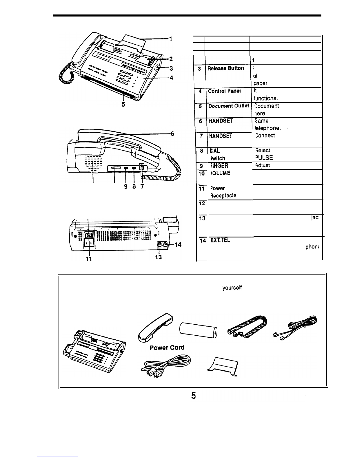
A Quick Look at Your Machine
No.
Part
Name
Function
1
Document Tray
iT supports the document.
2
Document Guide IT adjusts the document
Side View
Speaker lb
Rear
View
12
oaded.
sLIDE
it towards the front
9
10
11
12
13
14
IANDSET
Jack
IIAL
MODE
iwitch
?lNGER
Switch
IOLUME
Switch
sower
keptacle
Power Switch
TEL UNE Jack
EXKTEL
Jack
3f
the
unit
to open the
aper
cover.
:
controls the operating
Jnctions.
Document
feeds out from
lere.
same
as the regular
elephone.
.
Connect
the handset here
Select
the TONE or
WLSE dialing mode.
4djust
the ringer volume.
Adjust the monitoring
speaker volume.
Connect the supplied
power cord.
Use it to turn power on
and off.
A standard telephone
jack
to connect the unit to the
phone line.
Connect the answering
machine or regular
phons
if necessary.
Check your Equipment
Unpack your unit and examine the drawing below to familiarize
yourseff
with its parts and to make sure
none are missing.
Handset
Fax Paper
Handset Cord
Line Cord
Main Body
Document Tray
Page 7
A Quick Look at Your Machine
continued
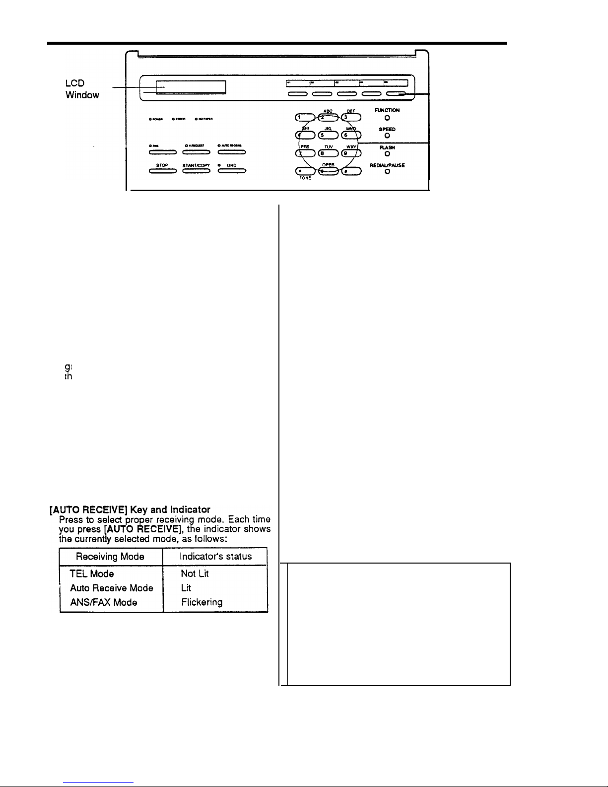
Control Panel
LCD Window
The window displays messages that instruct you
when operating your facsimile. In standby mode,
the windows displays the current time and date.
POWER
indicator
Lights when the unit is on. When the unit is in
use, it flickers.
ERROR
Indicator
Lights if something goes wrong either your unit or
the fax communication. The indicator flikers if the
machine’s thermal print head is overheated.
NO PAPER Indicator
Li
hts when the fax paper has run out. It also
ligats when the paper cover is opened.
[FINE]
Key and Indicator
Press to improve clarity of a poorly printed
document you are sending.The indicator lights
when the FINE mode activates.
[V.REQUEST]
Key and Indicator
Press to make a voice request while you are
sending or receiving documents. The indicator
lights when you initiate a voice request. The
indicator flikers if the remote party wants to talk to
you.
[STOP] Key
Press to stop an operation. The unit will return to
standby mode.
[START/COPY] Key
Press to start copy or fax operation.
_ One-Touch
Keys
_ Dial
Keypad
[OHD] HOLD Key and OHD Indicator
Press to dial numbers without picking up the
handset. The indicator lights when speaker
activates. Or, press the key to put a call on hold.
One-Touch Keys
Allows dialing the most frequently called numbers
at a touch of the keys.
Note: One-touch keys 04 and 05 double as
[YES] and [NO] key. You will use these keys
when you set User Options (see page 25).
[FUCNTION] Key
Use with other keys when performing certain
functions.
[SPEED] Key
Press before entering a
2-digit
speed dial
number.
[FLASH] Key
Press to take a second incoming call on the same
line.
[REDIAL/PAUSE] Key
Press when calling the last number dialed. Or,
press to insert a pause in dialing numbers.
Dial Keypad
It lets you manually dial a phone number, use a
speed dial number, or enter data to set up your
machine to match
your individual needs.
[TONE] Key
Use to produce touch tone or
pulse dialing.
Tones and Alarms
Your unit produces a variety of tones to
assist you In Its proper operation.
l
A short
tone sounds when you press a key.
l
5 short tones sound when an
error
condition occurs.
l
3 short tones sound when you completed
storing numbers.
l A long tone sounds when sending or
receiving is done.
6
Page 8
Setting Up
0
This section shows how to set up your fax
machine and prepare it to send and receive.
Follow These Steps
To set up your machine and prepare it to send and
receive faxes, follow these four steps:
l
Choose a proper location to install
your machine
l
Assemble your unit and hook it up to power and
phone line (see pages 8, 9).
l
Enter
your
unit’s ID number into the unit’s memory
(see page 12).
0 Install
fax paper in your unit (see page 11).
,
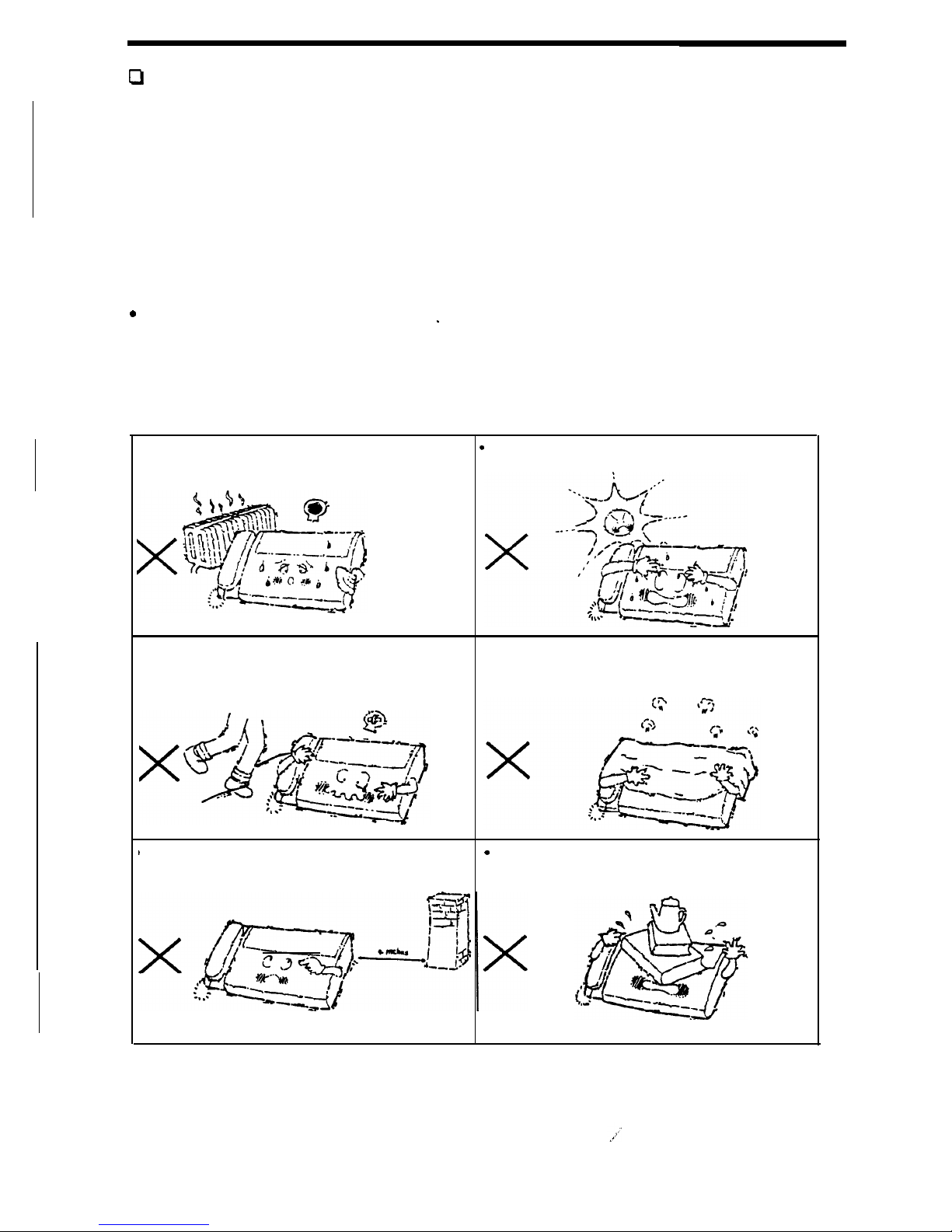
Choosing a Proper Location
A proper location for your fax machine helps ensure trouble-free operation. Select a location for
the
unit where:
It
is
away from heating or air conditioning
units.
.
It is not in direct sunlight.
Its cords are not in the way of normal
activities
l
The ventilation openings are not blocked.
1 It
is at least 4 inches from other objects.
.
Also, do not place objects on the top of the
unit.
7
Page 9
Assembling & Connecting
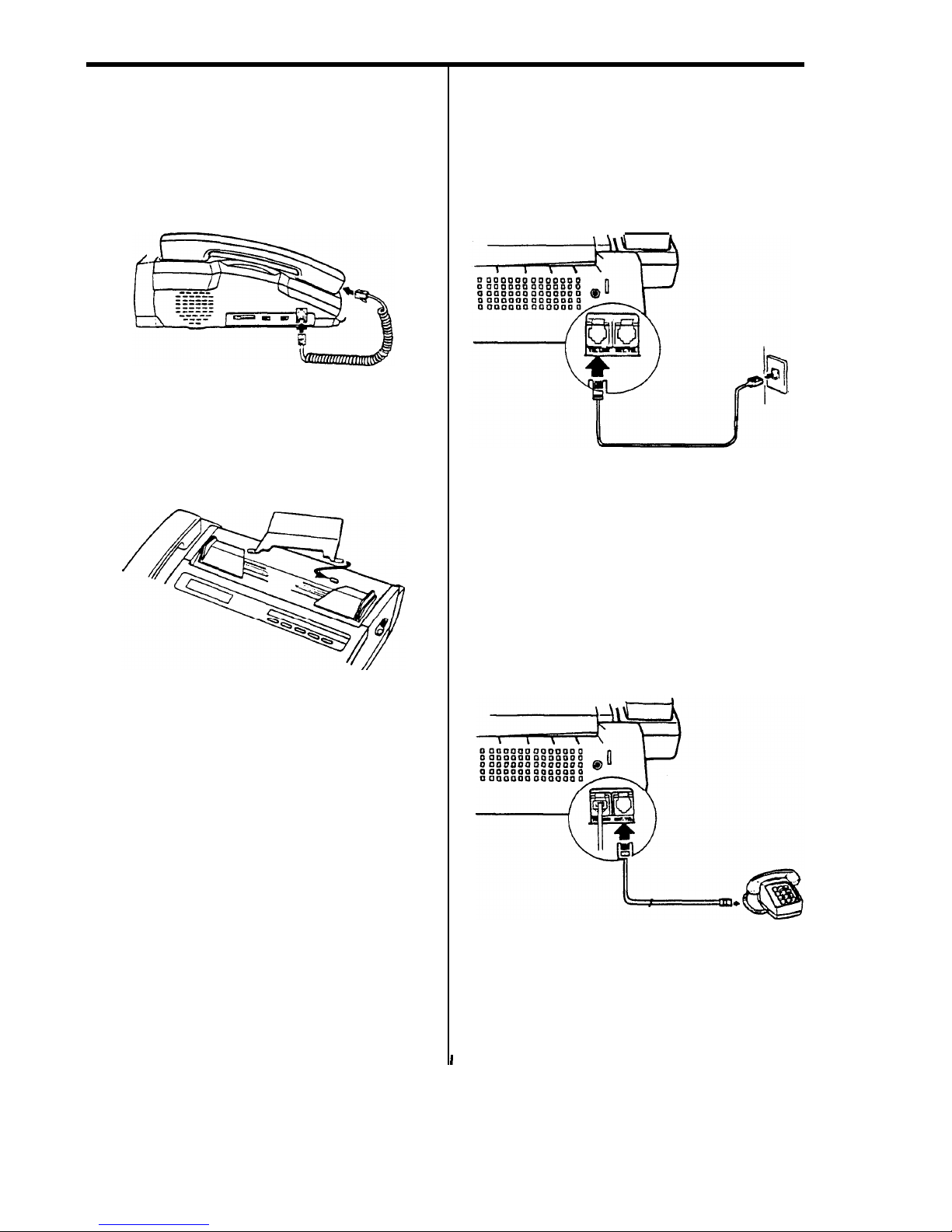
Installing the Handset
Plug one end of the handset cord to the jack on the
bottom of the handset. Then, plug the other end of
the cord to the HANDSET jack on the left side of
the machine.
Attaching the Document Tray
Insert one tab then flex the tray to insert the other
tab into the raised holes on the top of the paper
cover of the fax unit as shown below.
Connecting the Phone Line
Connect your machine in either of two ways:
l Plug one end of the line cord into the TEL LINE
jack on the machine and the other end into a
standard telephone wall jack.
l
If
you have a multi-line telephone, plug one end of
the line cord into the TEL LINE jack on the
machine and the other end into a jack on the
multi-line phone system.
Notes:
l If you install the unit in an electronic or digital
telephone system or PBX, it may not operate
correctly. To use the unit on such a system, you
may have to contact your local telephone
company and have them install a separate line
that bypasses this equipment.
I
8
l Many modern office buildings feature identical
wall jacks for telephone lines and data lines for
computers. If the computer terminals in your
office plug into wall jacks, make sure that you
plug your unit into a live telephone jack, not a
data jack.
Connecting
Extension Telephone
or Answering Machine
(if
necessary)
Plug one end of the modular cord into the EXT.TEL
jack on the rear of your machine. Plug the other
end of the cord into a modular jack on an answering
machine or a regular telephone you wish to use as
an extension.
Page 10

Assemblina &
Connecting
continued
Connecting the Power
Plug the power cord to the power receptacle. Plug
the other end of the cord into
a properly grounded,
three-pin AC power outlet.
Note: Use an outlet not shared with equipment that
generates electrical noise or consumes large
amounts of electricity, such as an air conditioner or
off ice copier.
Turning the Power “ON”
Press the Power switch to turn the unit on.
When you turn the power on, ‘SYSTEM INITIAL’
message appears briefly in the display window and
all indicators light briefly. After a moment, all
indicators are turned off, and the date, time are
displayed. (If the displayed time and date are
incorrect, don’t worry
-
you will change this
information in a moment.). This confirms your unit
works properly.
You may leave your unit on and standby mode 24
hours
a day, 365 days a year.
Notes: If nothing appears in the window, make
sure that:
l The power cord is properly connected and
plugged into the wall jack.
l The wall jack is ‘live’ and not switched off by a wall
switch or blown fuse.
Choosing Dial
Mode
Set the DIAL Mode switch on the left side of the unit
for the type of service you have (pulse or tone).
If you are not sure which type of service you
have, do this simple test.
1. Lift the handset and listen for a dial tone.
2. Press any number other than 0. If the dial tone
stops, you have a touch-tone service. Set the
DIAL MODE switch to “TONE”
3. If the dial tone continues, set the DIAL MODE
switch to “PULSE”.
9
Page 11

Setting Speaker Volume
The VOLUME switch on the left side of the unit
controls the loudness of the dialing tones you hear
through the speaker when you dial with the handset
down. You can set the volume to low (all the way to
the right), medium (center), or high (all the way to
the left).
Setting Ringer Volume
The RINGER switch on the left side of the unit lets
you adjust the ringer volume to three different
settings. Try all three to see which volume level is
best for you.
If you set the switch to “OFF”, your unit
doesn't
ring
when an incoming call comes in.
Assembling & Connecting
continued
10
Page 12

Loading Fax Paper
PAPER RUNNING OUT 3
You’re running low when the edge of the paper
is pink or black.
When you’re out of paper, the NO PAPER
indicator
lights
to let you know.
1. Open the paper cover by pulling the release
button toward the front of the unit. Alert tones
sound and the NO PAPER indicator lights when
the cover is lifted. Remove the empty paper roil
core, if any.
2. Place a new paper roll in
sure the paper exits from
shown.
the compartment. Be
the top of the roll as
Location of ‘SPACER’.
Note:
If you
are
using 210
mm wide paper, rotate
down the black ‘SPACER’ located in the paper
compartment to fit the width of the paper roll.
3. Pull the paper edge out about an inch from the
edge of the fax machine.
4. Close the cover by pressing down on the center
of the cover until it is secure. Tear off the excess
paper.
11
Page 13

Setting Date and Time
Your fax machine has a timer function. Note that the
time must be entered in 24-hour format (refer to the
box below). The date and time also appear in
various reports. In addition, they are added to the
top of all transmitted copies along with your name
and number if you set the feature to be activated
through the user options
(see page 25).
For times before
Noon
or
after Midnight, use the
same numbers as
12hour time. being sure to
use four digits; for
example, enter 2:00
AM.
as
0200, enter
9:30
AM.
as 0930.
For times from Noon
through Midnight, use the
entries shown in the table
at right.
For This Time Tvoe This
Noon
1200
1 : 00 P.M
1300
2
:oOP.M
1400
3 :OOP.M
1500
4
:ooP.M
1600
5 :OOP.M
1700
6 : 00 P.M
1800
7
:oOP.M
1900
8 :OOP.M
2000
9 : 00 P.M
2100
lo:
00 P.M
2200
11 :OOP.M
2300
Midnight
0000
Setting Up Basic Information
3. The LCD window displays the newly-set date and
time. After a moment, the next message will
appear.
jSET1
Setting Your Terminal ID
You can enter a self-identification message that will
print across the top of every page you send to
remote fax units. This message is made up of your
company name (any combination of the available
characters up to a maximum of 40) and fax number.
Along with your message, the remote fax unit will
also print out the time, the date, and number of
pages you send.
Entering your fax number also enables this
information to be displayed in the window of any fax
unit you communicate with.
j
To set or change the date and time,
press
[FUNCTION], [O]. Follow the steps below.
Your Terminal ID will help your faxing partners keep
track of who they are communicating with, and will
give them the information they need to contact you,
or follow up in case of a faulty transmission,
unreadable fax, or other problem.
I
SET DATE, TIME ?
1. Press [YES].
Note: Using one of the User Options, you can
prevent this information from printing on faxes (see
page 25).
MMDDYYHHMM
I
2. Using numeric keys, enter the month (MM),
datl
(DD), and year (YY) with a 2-digit number.
An
enter the hour (hh), and minute (mm) in
24-hou
format.
To begin setting your Terminal ID, press
[FUNCTION], [O]. Press [NO] at the prompt ‘SET
DATE, TIME
?’
on the window. Follow the steps
below.
For example, to enter September 15, 1992, 3:
31
P.M., you would type 09 for the month, 15 for
th’
date, 92 for the year, 15 for the hour, 30 for th
minute.
0
e
e
JSETI
1. Press [YES].
If you make a mistake while entering the dat
and time, press [NO]. The last entered number i
cleared each time you press [NO].
8
S
71
2. Enter your fax number (up to 20 digits). To delimit
the area
and
exchange code,
use
[REDIAL/PAUSE
Each time you press
[REDIAL/PAUSE
Hyphen is inserted.
If you make a mistake, use [NO] to backspace to
the error. or press [STOP] to cancel the
operation and start over.
12
Page 14

Setting Up Basic Information
continued
3. The number appears on the display. Check the
number and if it is correct, press [YES].
ENTER
NAME
4. Enter your name, for example,
AUDIOVOX
as
described below. Make sure the ID name
appears correctly, then press [YES]. Now, the
unit returns to the standby mode.
How To Enter Name
1.
2.
3.
Press the number key labeled with the character
you want. Press it once to obtain the number,
twice or four times
to
obtain the proper character.
(see below chart)
When the character you want appears on the
display, press
[*]
to confirm it.
Select further characters in the same way. Press
[REDIAL/PAUSE]
to enter a space.
Notes:
l
If you make a mistake while entering, press [NO]
to backspace and correct.
I
l To cancel entering name, press [STOP] in the
middle of entering.
llow
the chart to produce alphanumeric characters with the dial keypad.
Vumber
Keypad
[1]
[2] [3]
[4]
[5] [6]
[7]
[8]
[9]
[0]
First
Press
1
2
3
4
5
6
7
8
9 0
Second Press
Q
Q A
D
G
J
M
P
T W +
Third Press Z
B
E
H K N R
U
X
*
Fourth Press
.
C
F
I
L
I
0
S
V
Y
I
I
For example, to enter AUDIOVOX:
Press
[2]
twice, then
[*]
Press
[8]
three times, then
[*]
Press
[3]
twice, then
[*]
Press
[4]
four times, then
[*]
Press
[6]
four times, then
[*]
Press
[8]
four times, then
[*].
Press
[6]
four times, then
[*].
Press
[9]
three times, then
[*].
When completed, press
[YES].
13
Page 15

Receiving
0
This section shows how to receive faxes and
control the functions that affect the way you
receive faxes.
Manual vs.
Automatic Fax
Machines
Facsimile machines come in two basic types:
Manual fax machines require the sender to dial
the number, listen for a fax tone from the
receiving machine (or tell the receiving operator
to press the [START] key on their machine), and
then press [START/COPY] to send.
Automatic fax machines detect the presence of
the receiving machine after it answers, and
automatically send a document with no operator
intervention.
With the handset in the cradle using memory dialing
(see page
20)
your unit sends a document as an
automatic fax machine.
With the handset up, it sends a document as a
manual fax machine.
Your facsimile machine can receive documents
from either type of machine.
Choosing a Mode
Before you begin to receive faxes, select the proper
reception mode for the way you intend to use the
machine.
In TEL mode, you can use your fax machine as you
would use any regular telephone. Use this mode if
you typically use the unit to receive both voice calls
and faxes.
In AUTO RECEIVE MODE, your unit automatically
picks up to receive a fax after several rings. The
number of rings can be set through the User
Options (see page 25). Use this mode if you
typically leave your fax machine unattended.
In ANS/FAX MODE, the unit can share the same
telephone line with an answering machine
Notes:
D
Your unit is preset to the TEL MODE when it
comes out.
B
Once you choose a receiving mode,the mode will
not be changed even though you turn the unit off.
The unit restores the mode when you turn on its
power.
Receiving in TEL Mode
1.
To select the TEL (Manual) mode, press [AUTO
RECEIVE] repeatedly until the AUTO RECEIVE
indicator is off.
2. When the phone rings, pick up the handset.
3. When you hear a fax tone, press [START/COPY]
l When the other party is calling from a manual
fax machine, instruct him to press the
[START] key on their machine. When you
hear a fax tone, press your [START/COPY]
and hang up. The unit will receive the fax.
l If, when you answer the phone, you hear a fax
tone, someone is trying to send you a fax from
automatic fax
’
r:TART/COPY]
and
han,“,“,c:b”~ecei~~~~~
fax.
Receiving in AUTO RCV Mode
1.
2.
To select the AUTO RCV mode, press [AUTO
RECEIVE] repeatedly until the indicator over the
key lights.
When you get a call, the unit automatically
receives the document.
When a call is received from a manual fax
machine, your unit answers the call after
several rings which you set through the User
Options, and sounds a fax tone to the caller.
The caller hears the tone, and should know to
press the [START] key on their machine.
Then your unit receives the fax.
When a call is received from an automatic fax
machine, your unit automatically detects the
sending fax machine and receives the fax
automatically.
Notes:
l If you pick up the handset before your unit
answers, the unit switches back to TEL mode.
l Even when a fax tone is on the line, the unit might
fail to detect it and doesn’t receive the fax
because of the line instability.
14
Page 16

Receiving
continued
Receiving in
ANS/FAX
Mode
Note: To use ANS/FAX receiving mode, you have
to install an answering machine (see page 8).
This mode is not applicable for the standard
phone installed in EXT.TEL jack.
1.2.To select the
ANS/FAX
mode, press [AUTO
RECEIVE] repeatedly until the indicator flickers
When a call is received, the answering machine
answers and plays the recorded outgoing
message.
l If a fax tone or a certain time period of silence
is detected on the line by your fax machine
-
the call automatically switches over to the fax
machine and reception begins, overriding the
answering machine’s announcement.
l If someone wants to speak with you, the caller
can leave a message on the answering
machine.
Notes:
l If you have troubles receiving faxes in the
ANS/FAX mode, change the silence detection
time mode as described on page 25. This feature
in the user options will ensure fax reception when
a fax tone is not detected on the line by your fax
machine.
.
l If the sound level of the incoming caller is too low
due to
a poor telephone connection, the fax
machine and/or answering machine may not
function properly.
If the answering machine does not answer within
6 rings for
such reasons that recording message
is full on the tape or the answering machine is
switched off, your fax unit automatically switches
to the TEL/FAX mode and takes the call
according to the steps described in “Receiving in
TEL/FAX mode”. If the answering machine is
featured with a user
-
selectable ring counter, set
the machine to answer an incoming call within 4
rings.
l When you are using the TEL mode on your unit
and an answering machine is installed, you must
make sure you switch off the answering machine,
otherwise the OGM from the answering machine
will disrupt your telephone conversation.
l When your answering machine answers an
incoming call, a fax tone may be recorded while
your fax discriminates between
a voice and fax.
Your answering machine may indicate a voice
message has been left.
l Set your answering machine to VOX mode (If
applicable). VOX stands for
yoice
Qperated
Iransmission
and is the name given to the
answering machine facility which causes
disconnection when
a period of silence is
detected by the answering machine.
/
I
Some Message Guideline When You
Record Outgoing Message
The message that you record on your
answering machine should give clear
instructions to callers who may want to
send a fax or leave a message. Your
message should say “This is (your
company). If you would like to send a fax
please press your [START] key. If you
want to leave a message please speak
after beep”.
Keep your message as short as possible.
\
/
Receiving in
TEL/FAX
Mode
If you have set your unit to ANS/FAX mode and the
answering machine connected to the EXT. TEL jack
is switched off, or the answering machine is not
connected to your unit, your facsimile reverts to
TEL/FAX mode. In TEL/FAX mode, your unit
operates as follows:
d
When a call is received, if you do not pick up the
I.
2.
handset within 6 rings, your fax machine will
switch to AUTO RECEIVE mode.
When a call is received, if you pick up the
handset and hear someone, you can talk.
If
someone wants to send a fax, please instruct
him to press his [START] key. When you hear a
fax tone, press [START/COPY].
15
Page 17

Receiving
continued
Receiving Using the Extension
Telephone
When you are using a standard telephone and if the
telephone is connected to the EXT.TEL jack on your
fax machine (see page
8),
you can transfer a fax
transmission to the fax machine using the extension
telephone.
1. Answer a call on the extension telephone.
l Speak with the person on the other end of the
line.
l If a fax tone is heard when you pick up the
2.
3.
handset, go to step 3.
To receive a facsimile on the same call after the
conversation, ask the remote operator to press
the [START] key on their machine.
When a fax tone is heard, press
[*],
[9],
[*]
keys
on the extension telephone slowly in sequence.
If you still hear the fax tone from remote
machine, press
[*], [9], [*]
once again. [*], [9], [*]
is a remote receive start code which is preset at
the factory. The first and the last asterisk are
fixed, but you can change the middle digit [9] by
setting it through “Setting User Options”. See
page 25.
4. The call is transferred to your fax machine and
reception begins. Hang up the handset.
Canceling a Reception
Press [STOP] twice.
Even after pressing [STOP] once, your unit will
keep receiving until you press [STOP] again.
Once pressed [STOP], following message appears
to remind you of that your unit is communicating.
IN
USE !
I
To
cancel
reception anyway, press [STOP] again.
If you think you made a mistake, wait for a second
until your unit keeps on receiving.
Note: If your fax machine occasionally fails to
detect the remote start code, change the code for
other number.
16
Page 18

Important Receiving Facts
Voice Request
If you want to speak to the remote party who is
sending
a
document to you:
1. Press
[V.REQUST]
during the reception. The V.
REQUEST indicator lights to confirm your
request. But your request will not go through until
the unit finishes receiving the last document.
2. When receiving is finished, the call signal is sent
to the remote party’s unit. The remote party may
pick up the handset within 15 seconds if they
wish to speak.
If no one answers the request within 15 seconds,
the signal ends. The unit returns to the standby
mode.
3.
If
When the remote party responds, you hear a
warbling tone, and the V.REQUEST indicator
goes off. Pick up the handset and begin your
conversation
.
you
hear a warbling tone and the window
displays ‘VOICE REQUEST’ when receiving is
finished:
The remote party wants to talk to you. Simply pick
up the handset and say “Hello”. If you do not
respond to the voice request, your unit will print out
a call back message, which shows the telephone
number of the remote unit
SEP-05-92
14:46
PLEASE CALL BACK.....
PHONE NUMBER : 281 3950
Window Messages
During receiving, the window will display a
message similar to the one below to inform you of
its status or activity.
(REC.1
In this example, the number in the top of the
window is the telephone number of the sending fax.
‘REC’ means you are receiving,
"G3"
indicates the
communications standard observed by both fax
machine, ‘9 6’ indicates the transmission speed
(9600 bps), and the number following ‘P:’ is the
number of the page being received.
.
If a fax reception fails or your unit
detects
a
problem, it may display an error message in the
window. In order to clear the problem, refer to “Error
Messages” on page 28.
Identifying the Party Sending the
Documents
Most documents that you receive with your unit
have the other party’s ID printed out at the top of
the document. This is like the return address on a
letter. You can see at a glance who is sending the
document. The example below shows a typical
document with the ID printed out at the top.
Note: The amount of information that appears in
the ID depends on the type and settings of the
facsimile unit that is sending the document.
SEP-1892
12:15
AUDIOVOX
TEL:516-233-3300
P:05
17
Page 19

Important
Receiving Facts
.
Clearing Paper Jams
If the fax paper jams, DO NOT pull it out. Doing so
could damage your fax unit. To clear a fax paper
jam, open the paper cover by pulling the release
button toward the front of the unit. Then remove the
jammed paper.
Reload the fax paper as described in “Loading
Paper.”
Fax Paper Storage
Fax
Fax paper has chemicals in it that can, over time,
cause
yellowing, fading, and curling.
Following these storage guidelines should keep
your received faxes and your unused fax paper
serviceable as long as possible.
l
To
extend its shelf-life, store unopened
packages
of
thermal paper at or beiow 76°F and 65% humidity.
If the package has been opened, store it away from
direct light. Heat and humidity darken the of thermal
paper.
l
Store your received faxes away from direct sunlight
and at a temperature below 105°F. Heat and
humidity darken the the thermal paper and fade the
image.
B
Avoid storing faxes in contact with blueprint
(diazo) copies and plastic film or binders. The
chemicals in these materials may fade the image.
l
Avoid applying tape to the imaged area on faxes.
The chemicals in some transparent tape
adhesives may fade the image.
l
Avoid storing faxes with the imaged side together.
The printed image may transfer from one copy to
the other.
For indefinite storage, we recommend you copy
your received faxes using a standard office copy
machine, and store the copy instead of the
original fax. Documents on plain copy paper are
less prone to the decay that sometimes
affects
faxes.
18
Page 20

Sendina
Q
This section shows how to prepare a document
and send it. it also shows how to take
advantage of features that save time or improve
the quality of your transmission, such as
onetouch or speed dialing, changing resolution and
contrast, and using your fax machine to make
copies.
Sending a Document
1. Place the document face down and adjust the
document guide to match the width of the
document.
Note:, Slide the guide smoothly to the left or right. If
you move it with great force, it might be
broken.
2.
Gently insert the leading edge of the document
into the loading slot until you hear a beep tone
and the machine has begun to grab the
document(s). After the document is secured, the
unit displays the standby mode. The document is
now loaded and ready to send.
Bee
Notes:
l You can stack up to five sheets of paper at one
time. Stagger the leading edge of the sheet
slightly and insert the sheets with a slight push to
assure smooth feeding.
Be sure the bottom sheet enters first as shown
below.
D
If you want to add documents while sending,
insert it into the loading slot so it is placed on the
top of the preceding one as shown
below
3.
4.
Pick up the handset and
dial
the number of the
remote fax machine you want to send to. You
can also use one-touch dialing or 2digit speed
dialing for this Step. See “Memory Dialing” on
page 20.
When the line is answered:
If you hear a fax tone, press
[START/COPY]
and hang up. Your unit starts sending.
If you hear a voice, instruct the answerer to
press the [START] on their unit. When you
hear a tone, press [START/COPY] and hang
up.
If you hear a busy signal. press
[START/COPY] and hang up the handset.
Your unit automatically
redial
the number and
send the document (see “Automatic
Redialing"
on page 20).
5. When the last page has been sent, long beep
sounds, and your unit hangs up.
Hint: To cancel sending at any time, press [STOP]
twice.
19
Page 21

Important
Sending
Facts
Memory Dialing
If you have stored frequently used numbers in the
unit’s memory, and if the remote party you are
calling is set to receive documents automatically,
you can send a document at the touch of a key or
using [SPEED] key and 2-digit number.
For information on storing numbers for memory
dialing, see “Storing One-Touch
&
Speed Dial
Numbers” on page 24.
To send document using memory dialing;
1.
2.
Load the document face down into the unit (see
page 19).
To dial the number assigned to one-touch key,
press the one-touch key.
To dial the number assigned to 2-digit number,
press [SPEED] and enter the
2-digit
number (01-
20).
The unit automatically dials the number, confirms
the connection and sends the document.The
messages on the LCD window tell you what step
is being performed.
Note: If you press one-touch key or 2digit number
which is not stored in the unit, warning tones sound.
Automatic Redialing
When you try to send a document using memory
dialing and the receiving unit is busy or does not
answer, (within 60 seconds), your unit will
automatically redial the number at 3-minute
intervals until it reaches the receiving unit. It redials
the number up to three times in case of no answer.
When you dial a number manually using the dial
keypad and the number is busy, either press
[START/COPY]
and hang up or hang up then press
[REDIAL/PAUSE]
to activate the automatic
redialing.
If there is still no answer, your unit hangs up. If the
receiving unit answers, your document is sent
automatically
The OHD indicator flickers and ‘BUSY REDIAL
?"
appears on the LCD window while the unit waits for
the 3-minute
interval time to indicate the auto
redialing
is being activated. If you want to redial the
lumber soon without waiting for 3 minutes, press
[YES]
The unit beeps each time it completes
redialing
If you answer [NO] against the message
BUSY REDIAL
?"
the unit returns to the standby
mode.
To cancel automatic redialing at
[STOP], or remove the document.
any time, press
Note: If you receive call while theunit waits for the
3-minute interval time in the middle of automatic
redialing, lift the handset. You can take the call and
the automatic redialing is canceled.
Handset Up, Handset Down
You can use any dialing method - manual, onetouch, or speed dialing
-
for manual faxing (with the
handset up) or automatic faxing (with the handset
down
To dial manually with the handset down, press
[OHD] first. You will hear a dial tone through the
built-in speaker and you can then dial manually the
telephone number using the dial keypad.
Leave the handset down when you think you are
dialing an automatic fax machine and don’t expect
the remote operator to answer. If the remote
operator does answer, a fax tone will inform the
operator that a fax is coming in.
If you do lift the handset to dial, be sure not to hang
up until the transmission begins. Hanging up before
the transmission begins will disconnect the line and
cancel the transmission.
20
Page 22

Window Messages
During sending, the window will display a message
similar to the one below to inform you of its status
or activity.
In this example, the number in the top of the
window is the telephone number of the receiving
fax. SEND’ means you are sending,
"G3"
indicates
the communications standard observed by both fax
machines, ‘9.6’ indicates the transmission speed
(9600 bps), and the number following ‘P:’ is the
number of the page being sent. If a fax transmission
fails or the unit detects a problem, it may display an
error message in the window. Refer to “Error
Messages” on page 28 to clear the problem and try
to send the document again.
Clearing Document Jams
If the fax unit starts to read the document and for
some reasons, stops without reading all of it, the
document might be jammed. The unit displays
‘DOCUMENT JAM’. DO NOT pull it out of the
loading. To clear the jam, open the control panel
using hand as shown below.
It will release the grip on the document. Wait until
the white roller in the unit stops moving. You can
then remove the jammed document without
damaging
your unit. Close the cover. ‘DOCUMENT
JAM’ message disappears and the unit returns to
the standby mode.
Note: If the roller doesn’t stop moving, lift the edge
of the document and pull it in the direction of arrow.
Important Sending
Facts
continued
Printing
Information on Sent
Pages
!
you have entered a Terminal ID message (see
lage 12),
your fax number and name - along with
le
date, time, and page number - will appear at the
,p
of each page at the receiving end.
sy
setting one of User Options, you can choose
Jhether
to print this information directly over
thatever is at the top of each page, or not.
21
iE?-16-92
12:15
AUDIOVOX
TEL:51
6-233-3300
P:oS
i
Page 23

Important Sendina Facts
continued
Voice Request
If you are sending a document and want to
speak to the remote party;
1. Press
[V.REQUEST]
while sending. The V.
REQUEST indicator lights to confirm your
request. But your request will not go through until
the unit finishes sending the last document.
2. When sending is finished, the call signal is sent
to the remote party’ unit. The remote party may
pick up the handset within 15 seconds if they
wish to speak.
3.
If
If no one answers the request within 15 seconds,
the signal ends. Your unit returns to the standby
mode.
When the remote party responds, you hear a
warbling tone, and the V.REQUEST indicator
goes off. Pick up the handset and begin your
conversation.
you hear a warbling tone and the window
displays ‘VOICE REQUEST’ when sending is
finished;
The remote party wants to talk to you. Simply pick
up the handset and say “Hello”.
If you do not respond to the voice request, your unit
will print out a call back message, which shows the
telephone number of the remote unit.
SEP-m-92
14:a
PLEASE CALL BACK.....
PHONE NUMBER : 281 3950
22
Confirmation Report
A confirmation report will be printed out after every
send operation if you have selected this feature to
be activated by answering [YES] to the prompt
‘CONF. REPORT
?’
while setting “User Options”
(see page 25). Example is provided on page 26.
Page 24

Controlling Transmission Quality
Preparing a Good Original
To prevent jamming and ensure good results on
receiving fax machine:
.
.
Remove all staples, clips and tape from
original documents.
the
the
If you must re-fax a document that was faxed to
you, we recommend that you make
a copy of it
on a regular office copier, and fax the copy for
better transmission quality.
To create good quality original documents, do the
following:
l Type them instead of writing.
l When writing, use a felt-tip pen and black ink.
l Use white paper.
Do not try to send documents that are:
l
Wet or damp
l Covered with wet ink or paste
l Too thin (such as onionskin, airmail paper or
pages from a magazine)
l Chemically processed (such as pressure-sensitive
paper or carboncoated paper)
l Coated (such as glossy paper)
l Too small or short (such as a label or card)
l Made of cloth or metal
Use an office copier to piece together several small
originals or make a standard size copy of an
original which is too small to load in your unit.
Page
&
Document
Size
Limitations
Your unit accepts original documents no smaller
than 6 inches wide by 8.5 inches long, and no
larger than 8.5 inches wide by 59 inches long.
Do not attempt to load 2 or more documents into
the unit when the documents are too thin or too
thick.
These documents might fail in automatic
feeding. Feed one sheet at a time. Refer to the
following chart for acceptable thickness.
2 or
more
sheets
Single sheet
Thickness of
Document
0.08~0.13mm
0.075-0.15mm
Jote:
Make a standard copy by using an office
:opier
to send the document of
unacceptable
hickness.
Setting the Resolution
four unit allows to send a fax at a higher resolution.
Jse FINE resolution to send very detailed
documents with intricate drawings or small type.
Transmission time will be increased if FINE, mode is
set but the results will look better at the receiving
end
Vote: A document must be loaded into the unit for
:his
function to be operated.
To send a fax in FINE resulution, press [FINE]
Defore
dialing, the FINE indicator lights to confirm
;hat
the FINE mode is activated.
To see how your document will look at the receiving
end, use
your unit to make a copy with whatever
settings you like (NORMAL or FINE mode).
Making Copies
Your fax unit doubles as a handy copy machine.
1. Load the document face down into the unit.
2. Adjust the resolution of document by using
[FINE], if
necessary.
3.
Press
[START/COPY].
Note: If you copy 2 or more pages, be sure the
bottom sheet enters first.
23
Page 25

Storing One-Touch &
Speed
Dial Numbers
0
Instead of manually dialing numbers, you can
use either one-touch keys or 2digit speed dial
numbers to quickly dial the numbers that have
been stored in your unit’s memory. You can
store up to 20 telephone numbers of up to 34
digits each and the corresponding destination
names of up to 20 digits each. Storing name is
optional.
Each number entered is called a “location”.
Locations
01
through 20 are assigned to
speed dial
numbers. Locations 01 through 05 are also
assigned to one-touch keys.
Notes:
l Locations 01 through 05 could be dialed by either
one-touch keys or speed dial numbers.
l If you make a mistake while entering a number,
press [STOP] snd start over again.
To begin storing numbers, press [FUNCTION],
[1],
then follow the steps below.
/I
1. Press [YES]
(LOCiTIONl
2. Enter a
2-digit
number (01-20) under which you
want to assign the telephone or fax number.
Note: If the window says ‘CANCEL
?",
that means
there is already number assigned to that location.
To delete the previous number, press [YES]. Then
the unit deletes it and waits for you to enter new
location number. Or to start over with a different
location, press [NO].
3.
Enter the fax number or telephone number you
want to store. You can use any key on the
keypad, including
[*]
and [#].
Pressing
[REDIAL/PAUSE]
between numbers
adds a 3-second pause each time it is pressed.
(ENTER]
4. If you want to identify the number with a
destination name, enter the desired name as
described in “How to Enter Name” on page 13.
When the desired name entered and appears on
the window, press [YES].
If you do not want to store a name, just pres
[NO] without entering name.
To
verify
Your Stored Numbers
Print the location number list to verify
your one-touch telephone and fax
number entries and speed dial
\
telephone number entries (see page 26)
/
When completed, press [YES].
24
Page 26

Settina User Options
~
The option settings for your machine are preset
at our factory. If you do need to change the
settings,first print out the options list to see the
current option settings (see page 27).
Note: To return the unit to the standby mode in the
middle of setting user options, press [STOP].
To set or change options, press [FUNCTION]
then press [2]. Following message appears.
jSET1
1. Press [YES].
and
2.
3.
4.
TEPd.
ID ?
I
Press [YES] if you want to set your fax machine
to have your Terminal ID
(TTI)
printed on each
page you send. Press [NO] not to have your
TTI
printed.
CONF. REPORT ?
I
Press [YES] if you want to set your fax machine
to automatically print out a confirmation report
after each transmission. Press [NO] if you do not
want this report to be automatically printed.
RINGS(1 - 7)
>_
Enter the number of rings (1 through 7) your unit
should wait before answers an incoming call in
AUTO-RECEIVE mode. Then, press [YES].
5. Enter the remote receive start code that allows
your fax machine to receive documents
unattended by entering the code on an extension
telephone (see page 16). Then press [YES].
Notes:
l You can enter any number digit from [0] to [9] by
using dial keypad.
l The remote receive start code is consisted of
[*],
[one digit],
[*].
The first and the last digit
[*]
are
fixed. You can change the middle digit only.
l Middle digit is preset to [9].
/L;ZITEDl
6. After a call is picked up by the answering
machine in the
ANS/FAX
mode, your fax
machine monitors the line. When your fax
machine detects a certain time period of silence
or the line released by the answering machine,
the call will be treated as a fax message and
your machine begins reception.
If you want to limit the silence detection time to
12 seconds, press [YES].
If you want to unlimit the silence detection time,
press [NO].
Now, you have completed
settings of the
optional features of your unit.
To review the
settings, print the options list (see page 27).
Notes:
l If you enter
[1],
the unit will answer calls on the
first ring.
l To give you time to answer normal calls when you
are home, set this option for at least four rings.
25
Page 27

Printing Reports
Q
The report function of your fax unit is used to
see what numbers you have stored, what
settings you have made, or what faxes you have
sent and received.
Before making changes, print out the list to
check the current settings. After making
changes, print the list to confirm the new
settings.
Note: The call back message is printed
automatically when
you do
not answer the remote
party’s voice request, and the confirmation report is
printed automatically only if the corresponding user
option is set.
To print out reports, press [FUNCTION],
[3].
Following message appears.
VI
1. Press [YES].
JLOC.1
2. Press [YES] to print the location number list, or
[NO] to skip it (see right-lower for a sample list).
[OPTIONS1
3. Press [YES] to print the options list, or [NO] to
skip it (see page 27 for a sample list).
/TX1
4. Press [YES] to print the transmission report, or
[NO] to skip it (see page 27 for a sample report).
VREpoRT
5. Press [YES] to print the reception report, or [NO]
to skip it (see page 41 for a sample report).
Confirmation Report
The confirmation report shows the results of each
transmission;
the telephone number of the remote unit, the
number of pages sent, start time, the elapsed time,
and the result of the transmission. The report is
printed out automatically every time you send a
document, provided you have set the unit to print
out the report using the user option feature.
SEP-0592 1421
PHCNENIABER :618358
PAGES
: 02
SARTTME :
09.05
14:19
ELApsEDnME :
0135
MCQE
: 9BXWNEMi
AEsuTs
:oK
Location Number List
The location number list shows the current one-
touch number and speed dial number settings.
Before changing or adding numbers, print this
report to check which numbers are currently stored.
And print this report after making changes to
confirm the new settings.
SEP-05-92
12:20
LOC.NO.
NAME
01
7144498765
NFCWATKN
a?
2452622
SYsm
10
507wlO
N!%YOII(
26
Page 28

Printing Reports
continued
Options List
The options list shows the current settings for the
user options.
Before changing options, print this report to check
how the options are currently set. Also print this
report after making changes to confirm the new
settings.
SEP-0592 14:12
TEL NO. :
5182334300
NAME : AUOIOVOX CORP.
OPTIONS
TERMINAL ID.
CONFIRMATION REPORT
NO
RING COUNT
2
REMOTE RECEIVE START CODE
t
.
9
SILENCE DETECTION TIME
UNLIMITED
Transmission Report
The transmission report shows records of your
sending activity and its results. The report shows
the date and time,
who it was sent to,
communication mode, how many pages were sent,
and its
results. When you request this report, your
unit prints last 10 sending operations.
SEP.0592
1452
Ta.No. :51&axml
WE :AlmwOXCfm?
&L--m
eaGLaEsi#m
z
me
cw51417 CulP
01
cm
itI
w5 1439
01'3F
02M
03
wl51r21
01'4r
01
at
a4
Bl@359
09.051425
our
01
Cu
Reception Report
The reception report shows the records of your
receiving activity and its results. The report shows
who received it, the date and time, the elapsed
time, how many pages were received and its
results. When you request this report, your unit
prints last 10 sending operations.
SEP-692 1452
rnN0.
:51623333W
NAME
.AlJMOVOXCCW?
at
m
ma51435
ortx-
01
'OK
02
745m4
WI5
14.37
01'25
01
OK
03
2al2%0
cwl511'33
01'02.
01 OK
01
tms5ll
WI51443
0212-
02 OK
27
Page 29

Maintenance
and Troubleshooting
Troubleshooting Guide
Many common problems have simple solutions. Check quickly through the following list before calling for
service.
Symptom
Possible Cause/Solution
Nothing appears on the window when the power
l Is the machine plugged in ?
switch is turned on.
l Does the wall outlet have power ?
The unit does not receive faxes.
l Is the AUTO RECEIVE indicator lit ?
l Make sure the paper cover is closed securely.
l Make sure the handset is in the cradle.
Receiving fails after you press [START/COPY]
The unit does not send faxes.
l Did you press [START/COPY] before hanging
up the handset ?
l
Are documents properly loaded, and face down ?
l Did you press [START/COPY] before hanging
up the handset ?
Received faxes are dirty or hard to read.
l Poor original or dirty scanning glass on sending
The unit does not make copies.
You get no dial tone.
machine.
l
Are documents properly loaded, and face down ?
l
Is the telephone line cord connected properly ?
I
If not, Connect the cord to TEL LINE jack.
l
Make sure the power switch is ON.
l
Is the handset curl cord connected properly ?
When you are sending or copying documents
l
The unit has overheated and shut itself off.
continuously, warning tone sounds and the
ERROR indicator flickers, then you can’t do
anything with the unit.
Let it cool down then try using again.
Automatic document feeder does not work
l
ADF rubber is dirty. Clean it (see page 30).
properly,
so 2 or
more
sheets feed
l If you still have problem on the automatic feeding
simultaneously.
replace it with new one.
The ERROR indicator is lit.
l
Communication error occurs. Try again.
l The recording paper or a document has
jammed
in the unit. In case of document jam, check if
the
thickness, length, and size of the document arc
acceptable for sending (see page 23).
28
Page 30

Maintenance and Troubleshooting
continued
Cleaning Components
When the copied documents are hard to read,
clean the machine’s scanning glass and white roller.
If they are dirty, the quality of the transmission
image and copy becomes degraded.
1. Lift the control panel using hand.
2.
Disassemble the white roller. Both ends of the
roller are terminated with bushings which are
snapped shut with small tabs. Push the tabs
slightly inwards in the direction of ‘A’, then rotate
in the direction of
‘8’
until it reaches the slot as
shown in the figure below. Then pull the roller
upwards in the direction ‘C’.
Bushing
with
tabs
Sate :
Be careful not to lose the bushing on one
md
of the roller when disassembling.
3. Wipe the roller clean with a soft
with alcohol. Then dry throughly.
cloth
dampend
Note : Do not use the document having contents
written by pencil on the back side. It causes the
white roller to be stain. When the roller becomes
dirty, the copied document will not reproduce clear.
4. Clean the scanning glass with alcohol as shown
below.
29
Page 31

Maintenance and Troubleshootina
continued
5.
If a ‘DOCUMENT JAM’ occurs, dampen the
lintfree cloth with water, and wipe the ADF rubber
and ADF roller clean as shown below.
Note:
If you still have problems in feeding
documents automatically after cleaning the
rubber and the roller, you may have to
replace them. Contact your dealer.
6. Assemble the white roller in reverse order of
disassembling. Then close the cover.
How a Fax Works
Facsimile is a system of sending printed or other
graphic information from one location to another by
producing a copy or “facsimile” of that information
d the remote location. A fax unit transmits audio
ones over the same telephone lines you use for
lerson-to-person conversation.
The facsimile process involves three basic steps:
1.
2.
Reading and converting the document into
electronic signals (audio tones).
Sending, or transmitting, the signals through a
telephone system, to another fax unit.
3. Converting the received signals into a “facsimile”
of the transmitted document.
This is a simplified explanation of the actual
facsimile process. Although all fax units operate by
this same basic process, specific operating
procedures differ from unit to unit.
About Facsimile Compatibility
The
CCITT
(Consultative Committee for
International Telephone and Telegraph), which sets
worldwide standards for data communication,
classifies facsimile devices into three groups. The
grouping is based on how a fax unit sends
information, in what form, and at which speed.
To simplify, you can think of fax units as being
grouped by speed: Group 1 includes 6 minute units,
Group 2 includes 3 minute units, and Group 3
includes sub-minute units. These speeds refer to
the amount of time it takes a fax unit to send or
receive a standard business letter over the
telephone lines.
Your facsimile is compatible with
CCITT
G3 mode
units.
30
Page 32

Specifications
Type of Unit
Desktop Transceiver
Communication Line
Public Switched Telephone Network and PABX
Compatibility
CCITT Group 3
Compression Scheme
Modified
Huffman,
Modified READ (MH/MR)
Modem Speed
9600/7200/4800/2400 bps
Resolution
3.85 line/mm, 7.7 line/mm
Scanning Method
Flat-Bed scanning using CIS (Contact Image Sensor)
Print Method
Thermal
Input Document Size
216 mm (8.5
“)
Effective Scanning Width
210 mm (8.27
“)
+/- 1%
Effective Recording Width 216 mm (8.5
“)
Paper Roll Size
30 meters
Power Requirement
AC 120V
- 22OV,
50-60 Hz
Power Consumption
9.5 W (Standby), 120 W (Sending, Receiving and Copying)
Temperature Range
10°C
to 35°C (50°F to 95°F)
Humidity Range
20% to 80%
;
RH (non-condensing)
Dimensions
334 mm X 249 mm X 88 mm ((W) X (D) X(H))
Weight 3.5 Kg (7.7 Ibs.)
When Service is Needed
If your problem persists, contact the dealer from
whom you purchased your machine. You may want
to jot down your dealer’s telephone number.
Service Telephone Number
:
For the most efficient service, jot down the
information requested below before calling:
Model No. of your machine
:
AFX-2500
Serial No. (on bottom of the unit):
Type of telephone jack:
Model and brand of facsimile you are trying to
communicate with:
Is your unit having problem in transmitting,
receiving or both ?
YES/NO
Does the same problem occur when you call a
different machine ? YES/NO
31
 Loading...