

Page 1
Fax, Phone
AUDIOVOX
AFX-1000
&
Copier
Operation Manual
a
Page 2

TABLE OF CONTENTS
CONTENTS
FCC/DOC
SERVICE
FCC Information
Label Identification
Type of Service
Telephone Company Procedure
If a Problem Arises
DOC lnformaton
INSTALLATION INFORMATION
Hearing Aid Compatible Telephones
Contents of Shipping Box
HOW TO USE THIS GUIDE
WARNING
INSTALLATION INSTRUCTIONS
PAGE
3
3
3
3
3
3
4
5
5
5
6
6
7
.-
7
7
7
7
8
8
9
10
11
12
12
12
13
14
AC Power Outlet Connection
Connecting the Telephone Handset
Telephone Line System
Telephone Line Connections
CONTROLS AND INDICATORS
Front View
Control Panel
Rear View
LOADING PAPER
PREPARING AND LOADING AN ORIGINAL
Preparing an Original
Loading an Original
SENDING A FAX
RECEIVING A FAX
Manual Phone Mode
14
Page 3

CONTENTS
Auto
FAX/TEL
Switching Mode
PAGE
14
TELEPHONE COMMUNICATIONS
Answering a “Voice Request”
initiating a “Voice Request”
SETTING
AUTO DIAL
Assigning Telephone Location Numbers
Auto Dialing
COPYING A DOCUMENT
POLLING RECEIVE
FUNCTION MODE
+=
_
FEATURE SETUP
TSI/CSI
ID Number Entry
Sender ID Message Entry (Alphanumeric)
USER OPTIONS ENTRY
REPORTS
15
15
15
16
16
16
17
18
19
19
20
21
How to Get Report Printouts
Options List Report
Transmission and Reception Report
Message Confirmation
Call Back Message
CLEARING PAPER OR DOCUMENT JAM
MAINTENANCE
Cleaning the Receiving Paper Roller
TESTING THE MACHINE
TROUBLESHOOTING
ERROR INDICATOR AND SOUND
SUPPLIES
Handling and Storage of Thermal Copies and Paper
SPECIFICATIONS
27
28
29
30
30
31
32
32
33
34
35
36
36
37
Page 4

FCC/DOC SERVICE
FCC Information
The following information is applicable only to facsimile machines installed in the United States of America:
Label Identification
This equipment complies with Part 68 of the FCC rules. On the bottom of this equipment is a label that
contains among other information, the FCC registration number and Ringer Equivalence Number (REN)
for this equipment. If requested, provide this information to your telephone company.
Type of Service
Model AFX-1000 is designed to be used on standard device telephone lines. Connection to telephone
company-provided coin service (central office implemented systems) is prohibited. Connection to party
line service is subject to state tariffs.
Telephone Company Procedures
The goal of the telephone company is to provide you with the best service it can. In order to do this, it
may occasionally be necessary for them to make changes in their equipment, operation, or procedures.
If these changes might affect your service or the operation of your equipment, the telephone company
will give you notice, in writing, to allow you to make any changes necessary to maintain uninterrupted
service.
If you have any questions about your telephone line, such as how many pieces of equipment you can
connect to it, the telephone company will provide this information upon request.
In certain circumstances, it may be necessary for the telephone company to request information from
you concerning the equipment which you have connected to your telephone line. Upon request of the
telephone company, provide the FCC registration number and the Ringer Equivalence Number (REN) of
the equipment which is connected to your line; both of these items are listed on the equipment label.
REN's
The sum of all of the
on your telephone lines should be less than five in order to assure proper
service from the telephone company. In some cases, a sum of five may not be usable on a given line.
Please check with
If a Problem Arises
If any of your telephone equipment is not operating properly, you should immediately remove it from your
your local telephone company.
telephone line, as it may cause harm to the telephone network. If the telephone company notes a problem,
they may temporarily discontinue service. When practical, they will notify you in advance of the disconnection. If advance notice is not feasible, you will be given the opportunity to correct the problem and
informed of your right to file a complaint with the
FCC.
3
Page 5

DOC Information
The following information is applicable only to ‘facsimile machines installed in Canada:
Notice: The Canadian Department of Communications label identifies
certified
equipment. This certification means that the equipment meets certain telecommunications network protective operational and
safety requirements. The Department does not guarantee the equipment will operate to the user’s satis-
faction.
Before installing the equipment, users should ensure that it is permissible to be connected to the facilities
of the location telecommunications company. The equipment must also be installed using an acceptable
method of connection. In some cases, the company’s inside wiring associated with a single line individual
service may be extended by means of a certified connector assembly (telephone extension cord). The
customer
should be aware that compliance with the above conditions may not prevent degradation of
service in some situations.
Repairs to certified equipment should be make by an authorized Canadian maintenance facility designated
by the supplier. Any repairs or alterations made by the user to this equipment, or equipment malfunctions,
may give the telecommunications company cause to request the user to disconnect the equipment.
Users should ensure for their own protection that the electrical ground connections of the power utility,
telephone lines and internal metallic water pipe system, if present, are connected together. This precau-
tion may be particularly important in rural areas.
CAUTION:
Users should not attempt to make such connections themselves, but should contact the appropriate
electric inspection authority, or electrician, as appropriate.
The Load Number (LN) assigned to each terminal device denotes the percentage of the total load to be
connected to a telephone loop which is used by the device to prevent overloading. The termination of a
loop may consist of any combination of devices subject only to the requirement that the total of the load
numbers of all the devices does not exceed
100.
Load number for the Model AFX-1000 is 13.
This digital apparatus does not exceed the
CLASS
A limits for Radio noise emissions from digital apparatus
set out in the Radio Interference Regulation of the Canadian Department of Communications.
Page 6
Hearing Aid Compatible Telephone
INSTALLATION
INFORMATION
The telephone handset attached to
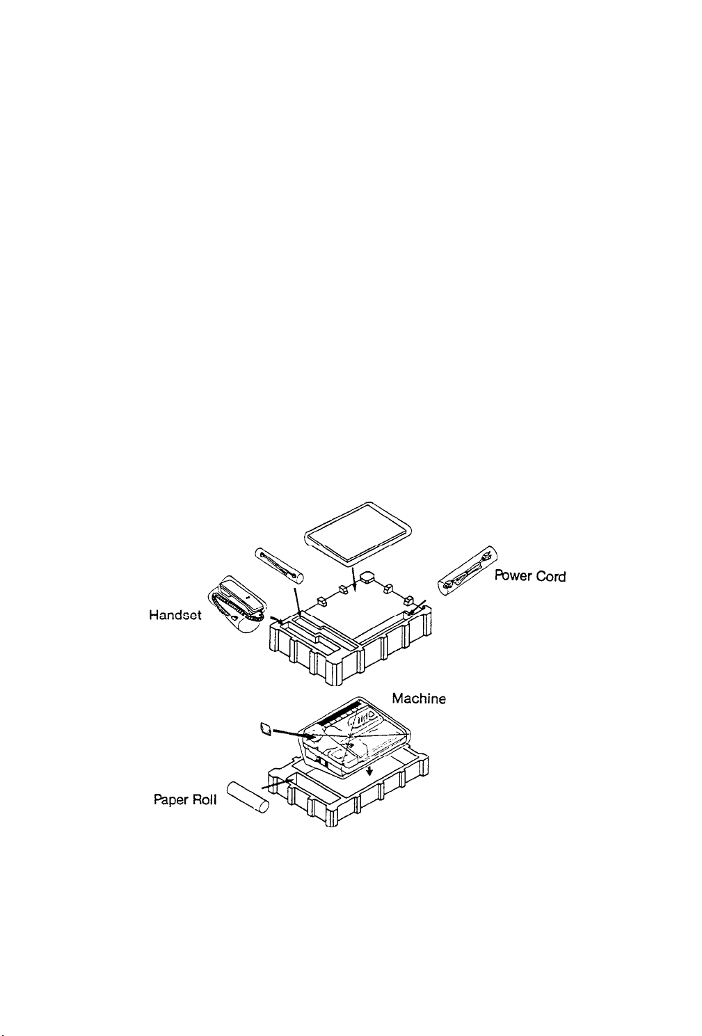
Contents of Shipping Box
Facsimile machine
1.
the facsimile machine is hearing aid compatible.
2. Telephone handset
3. Telephone line cord
4. Power line cord
5. Roll of thermal paper
6. Operator’s Manual
Also keep your receipt with this manual in case you need warranty services.
Operator’s Manual
&
Tel-Line Cord
Page 7

HOW TO USE THIS GUIDE
Please read this Operator’s Guide carefully before operating your new facsimile machine It contains all
necessary instructions for proper operation and maintenance of your FAX machine
FACSIMILE COMPATIBILITY
Your facsimile machine meets the
Group 3 facsimile machines. It automatically matches the
CCITT*
requirements to “talk” to (send to and receive from) Group 2 and
3-minute
and sub-minute speeds of
CCITT
Group 2 and Group 3 machines.
l CCl?T-Consultative Committee for International Telephone and Telegraph. This committee sets world-
wide standards for data communication.
WARNING
Reduce The Risk of Fire or Electrical Shock, Do not EXPOSE This FACSIMILE to Rain or Moisture.
To
Do Not Open Cabinet. Dangerous High Voltage is Present. Refer Servicing Only to Qualified Personnel.
1. VENTILATION: Slots and openings in the cabinet are provided for ventilation to ensure reliable operation
of the unit and to protect it from overheating. These openings must not be blocked or covered. Never
place your unit on a bed, sofa, rug, or other similar surface, on or near a radiator or heat register. This
unit should not be placed in a built-in installation such as a bookcase or rack unless proper ventilation
is provided or the manufacturer’s instructions have been adhered to.
2. OBJECTS AND LIQUIDS: Never push objects of any kind into this unit through openings as they may
touch dangerous voltage points or short out parts that could result in a fire or electric shock. Never
spill liquids of any kind onto the unit. Should spillage occur, unplug unit and have it checked by a technician before use.
6
Page 8
INSTALLATION
INSTRUCTIONS
This section gives instructions for connecting the transceiver to your telephone line and AC Power Outlet.
AC Power Outlet Connection
Use only the power cord supplied with your machine to connect the machine to an AC power outlet.
Connecting the Telephone Handset
Plug
the end of the flexible cord on the handset into the TEL Jack on the facsimile machine.
Telephone Line System
If you are installing this unit in an electronic or digital telephone system or PBX, it may not operate
correctly.
Consequently you may have to contact your local telephone company and have them install a separate
line that bypasses this equipment.
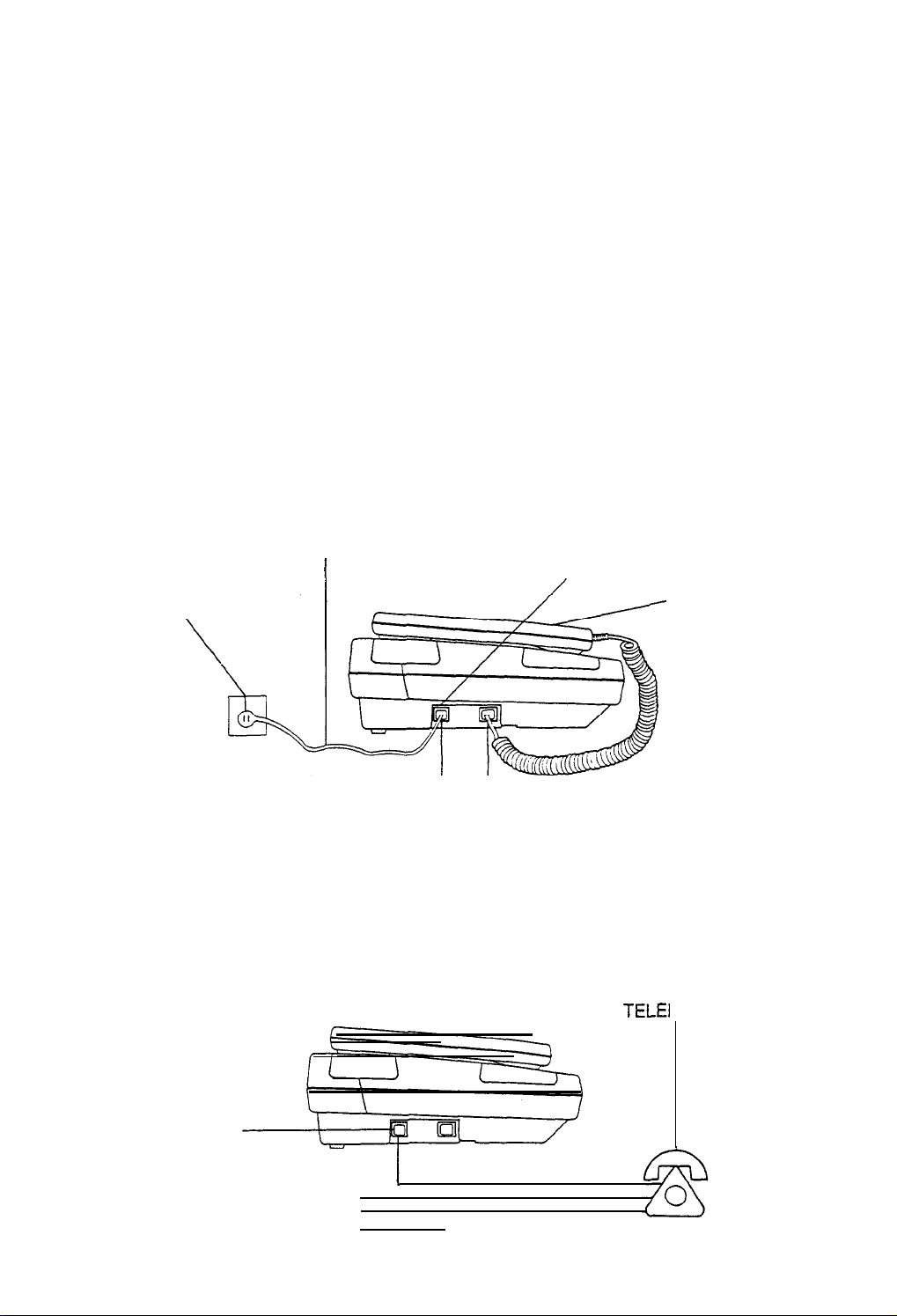
Telephone Line Connections
Connection Method No. 1
This is the normal connection method. Use this method if you intend to use the handset Auto-Answer and
Auto-Dial capabilities, as well as use the Handset for voice communications.
Plug one end of the TELEPHONE CORD into the STANDARD TELEPHONE CABLE CONNECTOR
(WALL
JACK) and the other end of the cable into the LINE connector on your facsimile machine.
TELEPHONE CORD
STANDARD TELEPHONE
CORD
CONNECTOR
I
TELEPHONE CABLE
CONNECTOR
(LINE)
ON YOUR MACHINE
TELEPHONE
HANDSET
LINE TEL
Connection Method No. 2
Use this method if you have a multiline telephone. Connect the unit to one of the lines. This allows the
FAX to Auto-Answer and Auto-Dial undisturbed on the attached line. You can use the remaining lines for
voice communications. Use the facsimile unit HANDSET to talk to the remote operator if necessary.
Note that this connection will require help from your local telephone company.
MULTI-LINE
TELEI
HONE
TELEPHONE CABLE
CONNECTOR (LINE)
ON YOUR MACHINE
TELEPHONE LINE 1
TELEPHONE LINE 2
TELEPHONE LINE 3
I
I
7
Page 9
Controls and Indicators
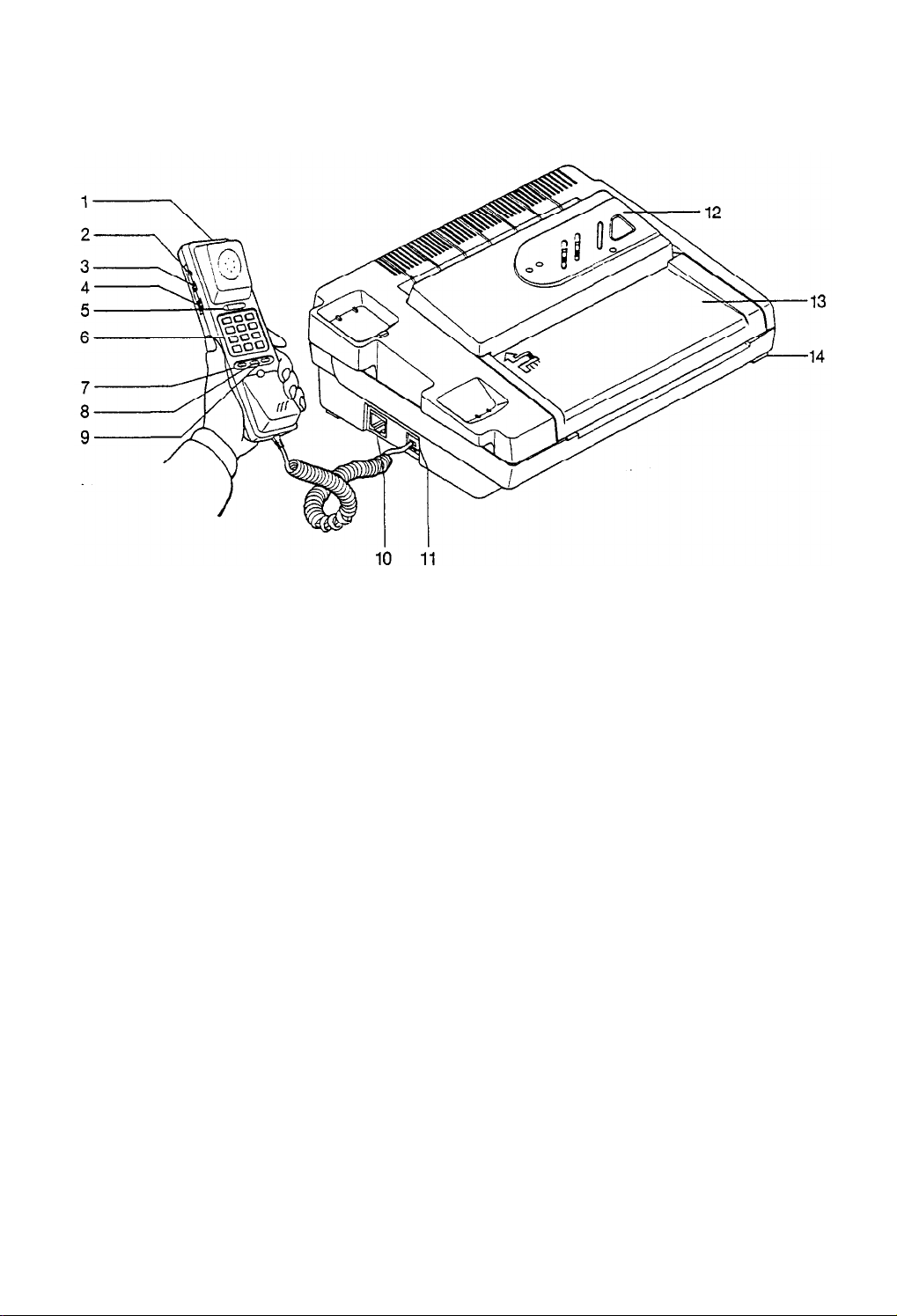
FRONT VIEW
1. TELEPHONE HANDSET
2 MEMORY KEY
Used to store telephone numbers for AUTO-DIAL. The machine can store a maximum of 18 digits
for
each number.
3. P/T SWITCH
A two-position switch for selection of tone or pulse dialing.
4. VOLUME
A three-position switch used to control the loudness of the ringer tone.
5.
HOOK SWITCH
6.
KEY-PAD
7.
RECALL KEY
This key activates the AUTO-DIAL. use the KEY PAD to enter stored numbers.
6.
PAUSE KEY
If your telephone is connected to a switchboard you may have to dial a digit to access an outside or
long distance telephone line. This usually requires a variable wait for a second dial tone
9.
REDIAL
KEY
This key is used to redial the last number you dialed.
10.
TELEPHONE CABLE CONNECTOR (LINE)
A standard telephone jack connects the unit to the telephone line.
11.
HANDSET JACK (TEL)
12.
CONTROL PANEL
13.
RECEIVING PAPER COVER
14.
PAPERCOVERRELEASE
Press to release the paper cover. Lift the cover to access the Paper compartment. When closing use
BOTH hands to push the cover down firmly with equal pressure on both sides of the cover to avoid
twisting it. It will “click”, when closed.
8
Page 10

Control Panel
5
6
c
/
/
3
4
/
1
2
STOP
Press this key to stop any machine operation in progress, reset all alarm and error conditions, and
cancel incomplete function selections. The unit will return to Standby Mode.
START/COPY
For manual FAX sending. Lift handset, dial. A beep tone will sound. Press start and hang up handset.
This key also used to start copy function.
FINE
Select FINE for high resolution to increase clarity on transmitted documents or for Reports in Function
Mode. (See page 27.)
NORMAL
Select NORMAL for normal resolution or for User Options in Function Mode. (See page 23.)
PHOTO
Select
PHOTO
for pictorial documents or for setting of
TSI/CSE
ID Number and Send ID in Function
Mode. (See page20).
FAX
4.
Select FAX for Auto FAX/TEL Switching Mode or for Testing the Machine. (See pages
14,33.)
PHONE
Select PHONE if you want to receive documents after you have a voice conversation or to enter
Function Mode (Send ID set,
5.
“IN USE” LED
TSI/CSI
ID Number set, User Option set, Report print out.)
Shows that power is on and the unit is ready to receive and send.
6.
“CALL” LED
Lights to confirm a voice request. (See page
7
8.
“PAPER” LED
15.)
Lights when paper is needed, or when paper cover or control panel is open.
9
Page 11
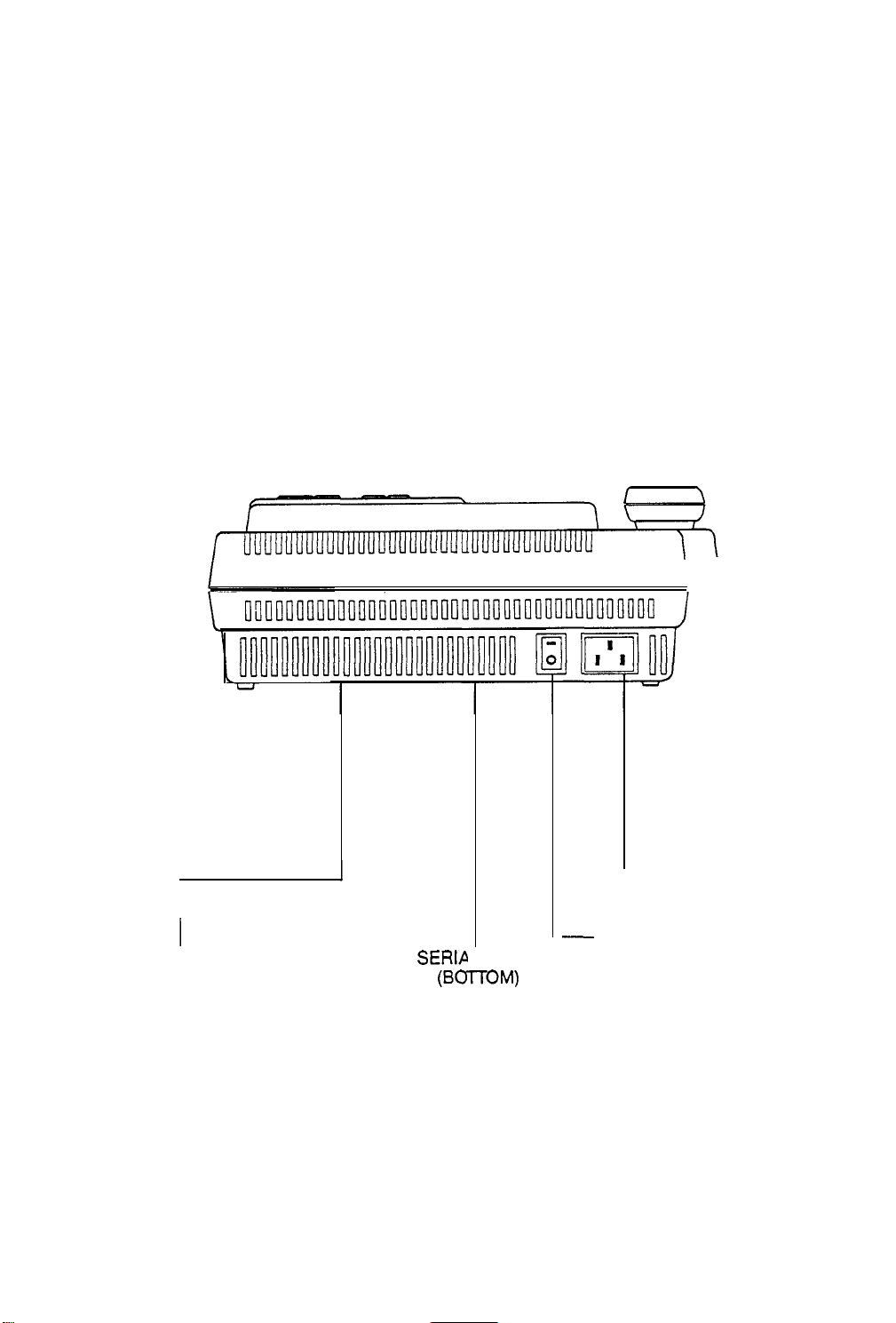
Controls and Indicators
REAR
VIEW
r
REGISTRATION
AND RINGER
EQUIVALENCE
NUMBERS (REN)
(BOTTOM)
SERIP
(BmM)
10
PLATE
POWER CORD CONNECTOR
-
POWER SWITCH (ON/OFF Switch)
Page 12
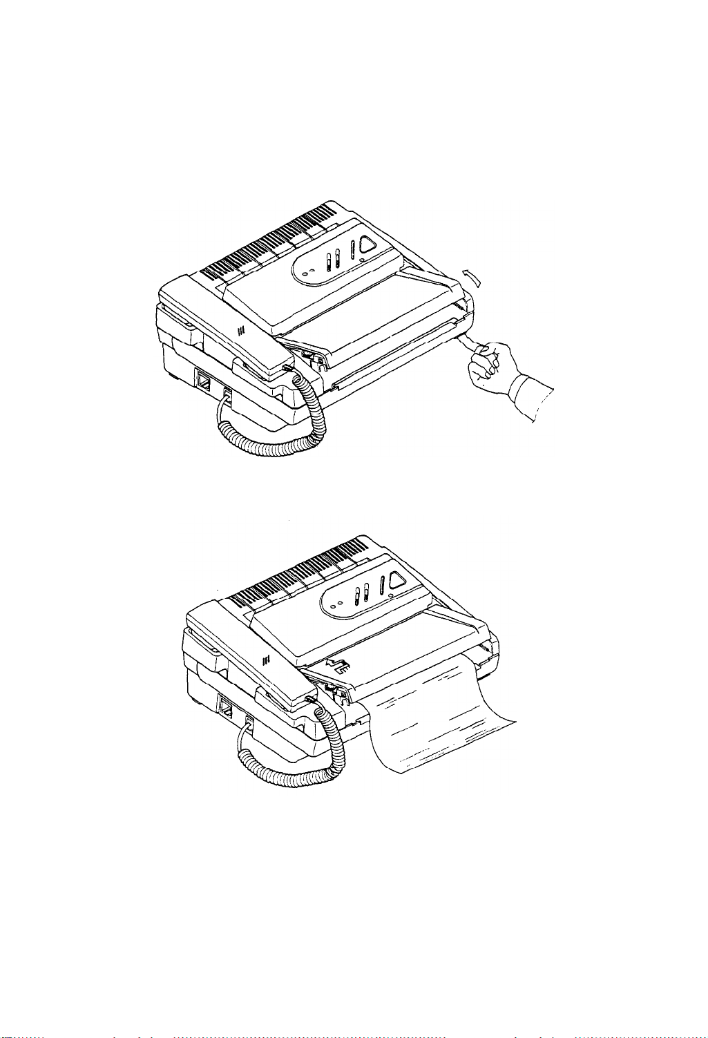
LOADING PAPER
1. Press the Paper Cover Release and lift the Paper Cover.
2. Remove the empty paper roll core, if in the machine.
‘3.
Lay
the new roll of paper in the machine with the paper edge rolling off from the top of the roll as
shown.
4.
Lay the leading edge of the paper on the black roller, aligning the left side of the paper with left side
of the roller. Leave an inch or so of paper projecting from the front of the machine.
5.
Close the Paper Cover. Exert equal pressure on both sides of the cover to avoid twisting it. It will “click”
when closed.
NOTE:
If paper is not properly loaded, you will not be able to copy or receive documents.
11
Page 13

PREPARING AND WADING AN ORIGINAL
Preparing an Original
Just as the appearance and readability of office copies is affected by the quality of the original, the quality
of the copy received at another facsimile machine is partly determined by the quality of the original document you transmit. If you transmit a poor quality document, the received copy may be difficult to read. Here
are several tips to help you create good quality original documents, and to improve the quality of “secondhand” documents you may use as originals.
Remove all staples and paper
clips. They
may cause the document to jam or you may damage the machine
If you are creating an original document:
l use a felt-tip pen, or type the document
l use black ink
l use white or light colored paper
You can also use an office copier to piece together several small originals or make a standard size copy
of an original too small or too large to load in the transceiver.
The FINE resolution feature can often increase the quality of the document. If your machines FINE
resolution feature cannot compensate for an existing document that is difficult to read because of light
images or a dark background, make a copy of it on an office copier. Many copiers can compensate for
poor originals to give you a better original to transmit.
Set the Switch to PHOTO position if your document has colors or various shades of gray.
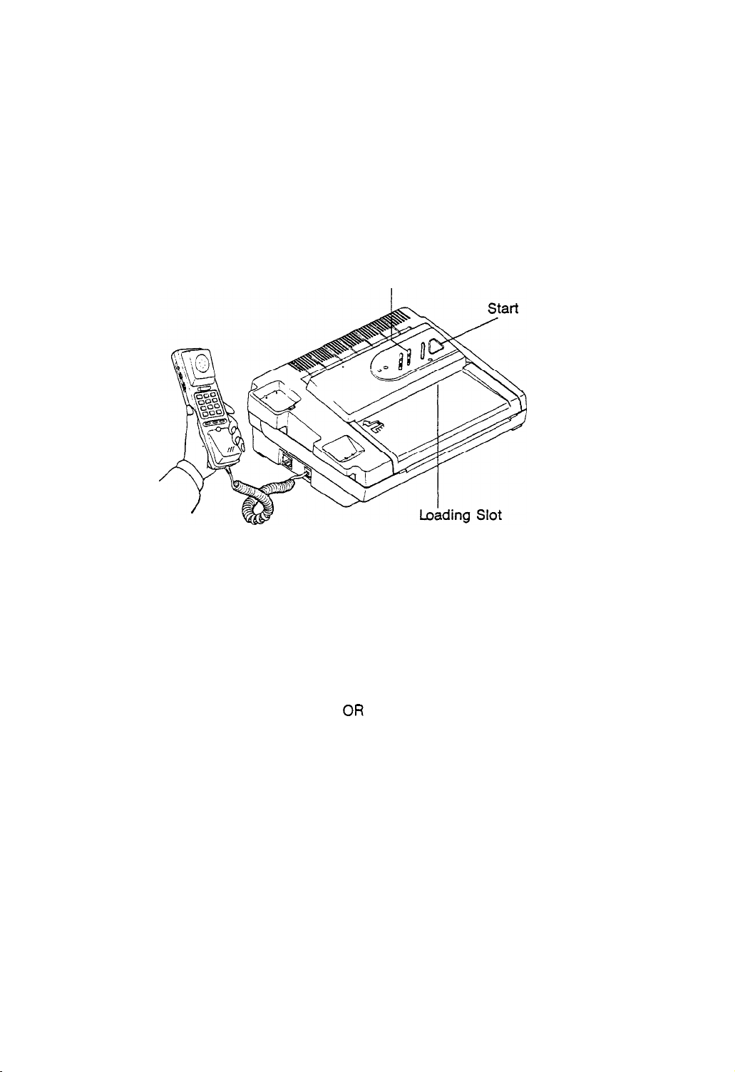
Loading an Original
Your personal facsimile transceiver will accept original documents with minimum dimensions of 7.1 inches
wide by 3 inches long, and maximum dimensions of 8.5 inches wide by enough length for 60 minutes.
Load documents as follows:
1. If IN USE LED is ON, the machine is ON and in Standby mode. If not, turn ON the POWER SWITCH.
2. Place the document FACE DOWN into the loading slot. The unit will grip the paper. The document is
now loaded and ready to be copied or transmitted.
NOTE: The Document Feeder can accept only one page at a time.
12
Page 14
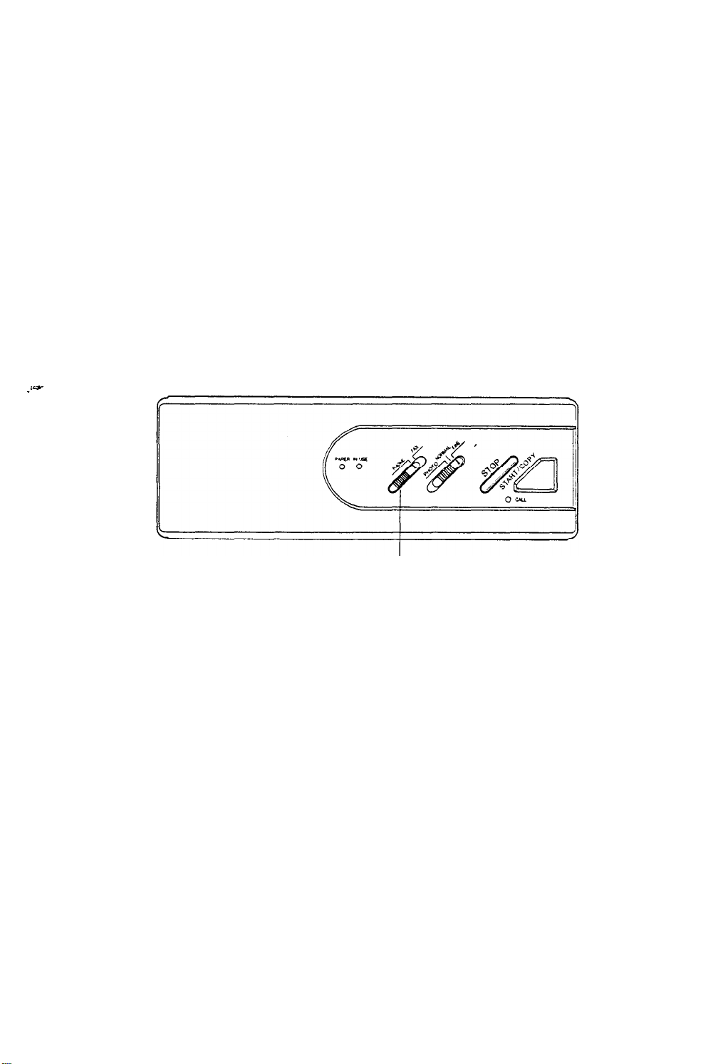
SENDING A FAX
1.
Make sure the power is ON. If IN USE LED is on, the power is ON. If not
turn
ON the POWER
SWITCH.
2. Place the document FACE DOWN and slide it into the loading slot. The unit will grip the paper.
NOTE:
The Document Feeder can accept only one page at a time
3. Set the Slide Switch to FINE to increase resolution at the receiving unit, or set the Slide Switch
to “Photo” to transmit a photo or halftone original with various shades of gray.
Slide Switch
Note:
When communication begins, IN USE LED blinks. If a communication error occurs, the
unit will sound a warning tone.
4. Pick up the handset and dial the receiving unit you want to call. Dial manually or use Auto-Dial.
(See page 16.)
5. When you hear
If
a person answers the phone, tell her/him
hear a tone, press the START key and hang
a tone, press
the START key and hang up the telephone handset.
to press the START key on the receiving unit. When you
up your phone.
Your machine will begin to transmit the original loaded in the document feeder.
6. After one page is transmitted, a four-second beep sounds and the unit holds the telephone line
open. You can insert another page to transmit to the receiving unit, during this 4 second period.
7. After sending, your unit will disconnect and return to the Standby mode.
CAUTION
If the machine starts to send the original and for some reason stops without sending all of it, DO
NOT pull it out of the loading slot. Open the control panel cover: (See page 31.) This will release the
gripping pressure and you can then remove the original without damaglng’your
machine.
13
Page 15
RECEIVING
A
FAX
Manual Phone Mode
Use
this mode if you want to receive document(s) after you have a voice conversation, or if you
plan to use your unit as a telephone.
1.
Make sure the unit is ON. If not, turn ON the POWER SWITCH.
2.
Make sure that the Slide Switch is in the PHONE position.
3.
You can answer the telephone as you normally would and use it for voice communications.
4.
After you complete your voice conversation and the remote operator is ready, press the START key
and hang up the telephone.
The calling machine then sends the document to your machine.
5.
When the last document is received, the unit will return to the Standby mode.
6.
_lY
Slide Switch
Auto
Fax/Tel
Switching Mode
l FAX-Auto
l Phone-Manual Phone Mode
Fax/Tel
Switching Mode
Use this mode to receive document(s) automatically when the machine is unattended or to have a
voice conversation.
-To set Auto
FAX/TEL
Switching Mode:
1. Make sure the unit is ON. If not, turn on the Power Switch.
2. Set the Slide Switch to FAX position.
-Operation
When an incoming call (Ring) is made your unit automatically determines whether the call is from a
FAX unit or a person:
l
IF A FAX is being sent: Your unit receives document(s) automatically.
l IF it is a phone call: Your unit will ring for about 18 seconds. If you lift the handset during this
period, you can begin a conversation.
If you don’t lift the handset, your unit
goes into auto fax receiving mode.
Note: If any communication error conditions occur, the unit
sounds a warning tone.
14
Page 16

TELEPHONE COMMUNICATIONS
You can use the built-in handset on your facsimile as a standard telephone. Use it as you would
use any other telephone. To place a call, pick up the Handset and use the Key Pad to dial any tele-
phone number.
Voice Requests
Voice Request allows you to talk with someone at the receiving or sending unit right after a document
has been sent or received.
Answering a Voice Request
Use this feature when you want to answer a Voice Request from operator.
If you hear a warbling tone when a fax is sent, pick up the telephone handset and begin
your
conversation.
When you complete your conversation, hang up the handset.
If you do not respond to the Voice Request, your FAX will print a Call Back Message. The message
will show the telephone number of the remote unit (provided that the remote FAX has transmitted
its identification number).
Initiating a Voice Request
Use this feature when you want to talk to the other operator after your facsimile machine has transmitted a document(s) to the other machine.
;.
Start
1.
Press the START key while your machine is sending or receiving documents. The CALL LED lights
up to confirm your request.
2.
A warbling tone sounds when the remote operator responds to your voice request.
3.
Pick up the telephone handset and begin your conversation.
4.
When you complete your conversation, hang up the handset.
Note: An answered Voice Request will end the interrupted send or receive session. Your FAX will wait
until all documents are sent or received before initiating
not answer a Voice Request within 15 seconds, your unit will automatically disconnect the phone line.
15
a Voice Request. If the remote operator does
Page 17

SETTING
Assigning Telephone Location Numbers
AUTO
DIAL
This section describes how to assign telephone numbers for Auto Dial.
The machine can store a maximum of 9 telephone numbers of up to 18 digits each. You can assign
telephone numbers to Auto Dial Locations using the handset Key Pad.
Pick up the Handset.
1.
Hold the Hook Switch down during programming procedure. With the Hook Switch depressed, use
2.
the Key Pad to enter the telephone number you want to store. You can use all of the numbers except
the l and #keys. Use the PAUSE key to add a pause.
After the complete number has been entered press the Memory Key on the side of the handset.
3
Using the Key Pad, enter the Auto Dial Location Number (l-9). The telephone number is now stored
4.
in the Auto Dial location.
Hang up the telephone handset.
5.
Note: If you enter a phone number in an already occupied memory address, the new number will
erase the existing
Auto Dialing
one.
Pick up the handset.
Press the RECALL key.
Use the Key Pad to enter the Location Number for the telephone number you want to call. The
unit will dial automatically.
Note: Make a list of Auto Dial locations and keep it close at hand.
16
Page 18

COPYING A DOCUMENT
1. Make
Note: The Document Feeder can accept only one page at a time.
2. Place the document
3. Set the Slide Switch
4. If you want a higher
5. If copying a photograph, set the Slide Switch to PHOTO.
6. Press the START key,
7. After one page is copied, a four-second beep will sound.
While the unit beeps, you can insert another page to copy.
sure the unit is ON. If not, turn ON the Power Switch.
FACE DOWN into the loading slot. The unit will grip the paper.
to NORMAL.
quality copy, set the Slide Switch to FINE.
Your machine
will
begin to copy the original loaded in the document feeder.
Your unit will return to the Standby mode, when the last page is copied.
Note: If document jamming occurs, the unit sounds a warning tone. (See page 31.)
Slide Switch
Page 19

POLLING RECEIVE
This feature lets you call an unattended machine and request a document that has been loaded and
is ready to be sent.
Note: 1. If the remote unit has a security poll code your facsimile cannot poll a document from
the remote unit.
2. This machine does not have a polling send function, so other units cannot poll a
document from it.
1. Make sure the unit is ON. If not, turn ON the Power Switch.
2. Make sure there are no documents loaded to send.
3. Pick up the handset and dial the remote unit which you want to poll.
4. When the remote unit answers, you will hear a high, steady tone. Press the STOP key and replace
the handset.
5. After your machine receives the document, your unit will return to the Standby mode. If any error
conditions occur, a warning tone sounds.
stop
18
Page 20

FUNCTION MODE.
This mode is used to set the functions listed below:
l
FEATURE
SET-UP
. REPORTS
l
TESTING THE MACHINE
if you want to enter a Function Mode from The Standby Mode, press and hold down the START key
about 4 seconds until the machine beeps. All of the LED lights will light. Make sure there are no
documents loaded to send when setting these functions.
FEATURE SET UP
This section describes the procedures used to set up the features of your facsimile machine.
The features include:
TSI/CSI
ID Number (your fax telephone number)
Sender ID (for example, your company name)
User Options Entry
Long Documents Yes/No
Terminal ID Print Message Yes/No
Terminal ID Print location
Receive Terminal Identification Yes/No
Group 2 TX Mode
Print Message Confirmation Yes/No
Auto Print Reports Yes/No
Ring Response Set
19
Page 21
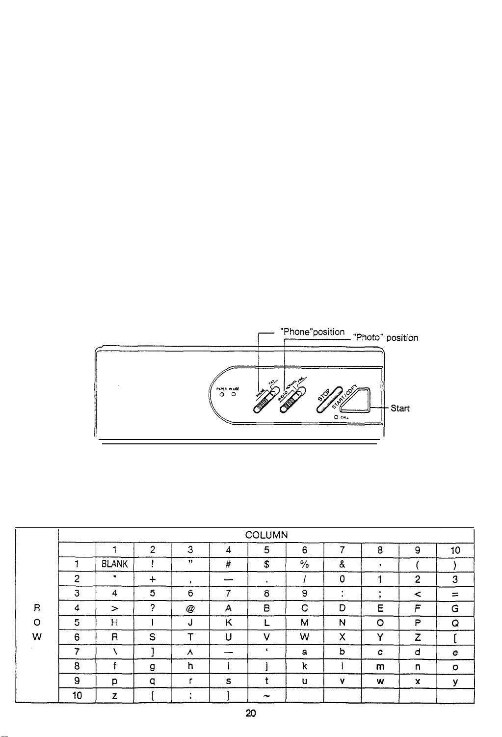
TSI/CSI
The
matically
ID Number Entry (Transmission Station ID/Called Station ID)
TSI/CSI
feature lets you enter your telephone number into the machine. Your machine will
send the number to the remote machine when a communications link is established.
auto-
To enter numbers and letters you use the START and STOP keys. The chart below shows how the
machine is set up to program numbers and letters. Just follow the step-by-step instructions below
and you will find it very easy to program your ID. (See next page for an example).
Press
and
1.
hold down the START key about 4 seconds until your unit beeps.
Set the slide switches to
2.
Find the number (or letter) you want to enter on the chart. Note its ROW and COLUMN location.
3.
For example, number
Select the ROW number by pressing the START key as many times as the ROW number (or letter)
4.
PHOTO
"7"
is at ROW 3, COLUMN 4.
position and PHONE position. Then enter your telephone number.
you desire.
5.
Press
STOP
Select the COLUMN number by pressing the START key as many times
6.
as the COLUMN number you
desire.
7.
Press STOP The first number you selected is now programmed.
8.
Repeat steps 3 through 8 for each number.
9.
Press the STOP key once more after you completely set your ID Number. Then enter Sender ID
Message Entry Mode. See next page.
Note: Your facsimile machine can accommodate 20 digits.
If you make a mistake or want to change an entry, you must go back to the beginning.
Page 22
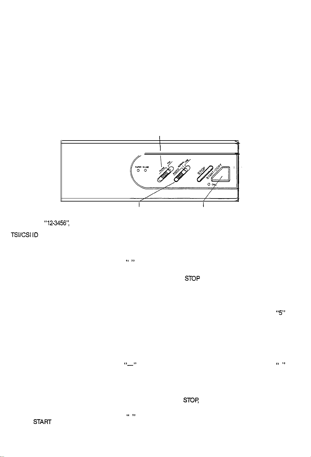
Sender ID Message Entry
The Sender ID Message feature lets you enter a message, such as your company name, that
will
print across the top of every page you send to remote machines. Along with your message, the remote
machine will also print out the number of pages transmitted. You can enter any combination of the
available characters up to a maximum of 40. To enter this mode directly, press and hold down
START
key for about 4 seconds.
10. Follow the same procedure for entering letters as for numbers. (Steps 1-9, preceding page)
11. After you completely set your Sender ID Message, press the STOP key once. The machine returns
to Standby
Mode.
“Phone” position
I
“Photo” position
I
I
Start
EXAMPLE:
TSVCSI IO
“12-3456’:
“SMITH CO.”
Number set
-press START twice
-press STOP
-press START 8 times
-press STOP
-press START twice
-press STOP
-press START 9 times
-press STOP
-press START twice
-press STOP
-press START 4 times
-press STOP
‘1 ,I
“2”
“
-1’
-press START 3 times
-press STOP
1
“4”
-press START once
-press
STOP
-press START 3 times
-press STOP
‘I I,
5
-press START twice
-press STOP
-press START 3 times
-press STOP
‘I .f
6
-press START 3 times
-press STOP
-press START twice
-press STOP
-press
START
10 times
-press STOP
‘1 8,
3
21
-Press
mode.
STOP
then enter Sender ID Message
Page 23

Sender ID Message Set
-press START 6 times
-press STOP
-press START twice
-press STOP
-press START 5 times
-press STOP
-press START 6 times
-press STOP
-press START 5 times
-press+XlP
-press START twice
-press STOP
-press START 6 times
-press
STOP
-press START 3 times
“S”
“M”
“ ,,
I
“T”
-press START 5 times
-press
-press
STOP
START
8 times
"0"
-press STOP
-press START twice
-press STOP
I‘ ,,
-press START 5 times
-press STOP
-Press the
STOP
key. The unit returns to Stand-
by Mode.
Note: If you make a mistake or want to change
an entry. you must go back to the beginning.
-press STOP
-press START 5 times
-press STOP
-press START once
-press STOP
-press START once
-press STOP
-press START once
-press STOP
-press
START
4 times
-press STOP
-press START 6 times
-press STOP
“l-l”
“space”
“C”
22
Page 24

USER OPTIONS ENTRY
This section describes the procedure for selecting the various optional machine features. These optional
features are usually selected during the initial setup of the machine and there should be little need
to change them thereafter.
Note: Before you begin, print the Options List report to see the current option settings. (See page 28.)
This facsimile allows you to set the following options:
Option
LONG DOCUMENTS
TERM ID (Terminal identification)
INSIDE
RTI
(Receive Terminal identification)
G2 (Transmission Mode. See page 6)
MESSAGE CONFIRMATION REPORT
AUTO PRINT REPORTS
Function
Transmits documents of unlimited length or to a maximum of
59 inches.
Transmits sender ID which prints at top of document.
Transmits sender ID and prints it within
Prints
RTI
at bottom of
Allows FAX to transmit
each page you receive.
in G2 mode.
8lhxil
area.
Prints out a message confirmation report after each transmission.
Prints out a report after every 25 transmissions or receptions.
ANSWER ON RING
Allows you to select the number of times the phone rings
before your machine answers.
23
Page 25

To
Set
Options:
“Phone” position
“Normal” position
I
Press and hold down the START key until your unit beeps.
:-y .
Set
Slide
Switches to PHONE position and NORMAL position. You are now in User Options Entry
Mode and can select the options you want.
1. LONG DOCUMENTS . . . . . . . . . . . . . . . . . . . . . . . . . . . . . . . . . . . . . . . . . . . . . . . . . . . . . . .
Press the START key if you want to transmit documents of unlimited length.
Or press the STOP key to limit the page length to a maximum of 59 inches.
I
Start Key
. YES/NO?
24
Page 26

2 TERM ID . . . . . . . . . . . . . . . . . . . . . . . . . . . . . . . . . . .
..~...........................YESINO?
Press the START key if you want your machine to send your Sender ID Message at the top of each
transmitted page.
Or press the S
TOP key if you don‘t want this message sent, then proceed to step 6.
3. TERM ID INSIDE . . . . . . . . . . . . . . . . . . . . . . . . . . . . . . . . . . . . . . . . . . . . . . . . . . . . . . . . . . YES/NO?
Press the START key if you want the Sender ID Message within the top area of the document.
Or press the STOP key if you want a space added to the top of the transmitted documents for the
printing of the Sender ID Message.
RTI
(Receive Terminal Identification). . . . . . . . . . . . . . . . . . . . . . . . . . . . . . . . . . . . . . . . . . . YES/NO?
4.
Press the START key if you want your machine to print an
RTI
(Receive Terminal Identification)
message at the bottom of each page you receive.
Or press the STOP key if you don’t want this message printed.
5. Group
2..................................................................YES/NO?
Press the
START
key if your machine is having difficulty in transmitting clear copies and you
suspect it may be due to poor telephone line conditions. This will allow your machine to transmit
CCITT
only in the
Or press the STOP key to allow the machine to transmit at the normal
Group 2 mode which may help to correct the problem. (See page 6.)
CCITT
Group 3 mode. (If the
remote unit is Group 2 only, your machine will automatically switch to Group 2.)
6. MESSAGE CONFIRMATION REPORT..
Press the
START
key if you want your machine to print out a Message Confirmation Report after
. . . , . . . . . . . . . . . . . . . . . . . . . . . . . . . . . . . . . . . .
YES/NO?
each transmission.
Or press the STOP key if you don’t want this report to print after each transmission.
25
Page 27

7. AUTO PRINT REPORTS
. . . . . . . . . . . . . . . . . . . . . . . . . . . . . . . . . . . . . .
s
.
. . . . . . . .
.
s
.
.
.
YES/NO?
Press the START key if you want the Activity Report to automatically print after every 25 transmissions or receptions.
Or press the STOP key if you don’t want this report to automatically print.
8. ANSWER ON RING
Press the START key as many times as the number of rings your machine should detect when
receiving an incoming call before it will answer the call (O-7).
Press the STOP key, then this number will be set and the unit returns to Standby Mode.
Print the Option
List
Report to Verify your settings. (See page
28.)
Note: Press STOP if you want the machine to answer calls immediately.
26
Page 28

REPORTS
This section describes the reports that
These reports include the following:
-Options List
-Transmission and Reception Reports
-Message Confirmation
-Call Back Message
.
“Fine” position
the unit produces.
“Phone” position
I
I
/
Start Key
/
How to Get Report Printouts
The following procedure will allow the machine to print out the report(s) you desire:
Press and hold down the START key until your unit beeps.
1.
Set the Slide Switches to PHONE position and FINE position. You’ll be in the Report Mode, and can
2.
now print out the reports.
Press the START key if you wish to print out the Options List Report. The machine will print out the
3.
Options List and return to Standby Mode.
STOP
Press the
4.
Press the START key if you wish to print Transmission and Reception Reports. The machine will print
key if you don’t wish to print out the Options List. Then proceed to step 4.
out the reports and return to Standby Mode.
SKIP
Press the
key. Then the unit returns to Standby Mode.
27
Page 29
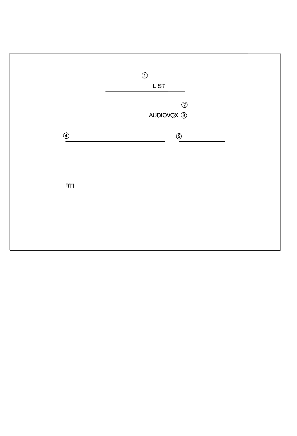
Options List Report
This report lists the optional features that are set up on
0
OPTIONS
LIST
TEL NUMBER: 5162317750
NAME
@ OPTIONS
LONG DOCUMENTS
TERM. ID
INSIDE
RTi
G2
MESSAGE CONFIRMATION REPORT
AUTO PRINT REPORTS
ANSWER ON RING
The Options List Report contains the following information.
AUDIOVOX
:
@
@
@ STATUS
YES
YES
YES
YES
NO
YES
YES
4
1. Report Title
2.
TSI/CSI
3. Your machine’s Station Name (Sender ID)
4. Options available
5. Status
ID Number
28
Page 30
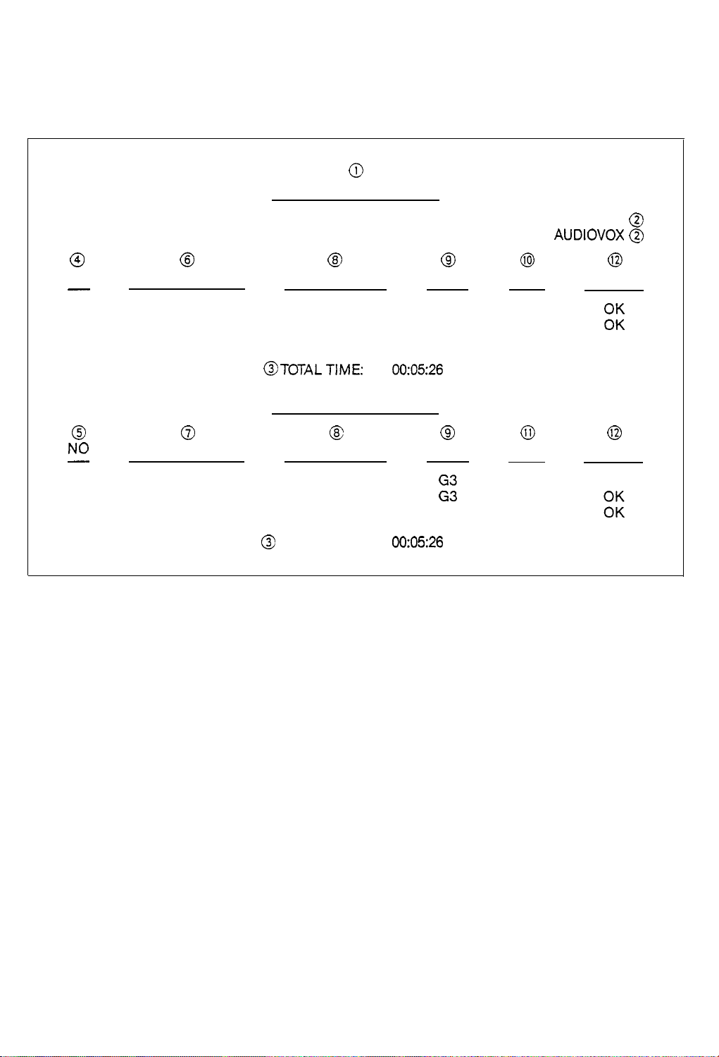
Transmission and Reception Report
These reports give you information on up to 25 transmissions or receptions.
0
TRANSMISSION REPORT
TEL NUMBER: 5162317750
NAME
0
NO
-
01
00
02
PHONE NUMBER ELAPSED TIME
0
NO
-
00
01
02
The Transmission and Reception Report contains the following information.
PHONE NUMBER
@ @ @ @
MODE
2136370254
6916213
4049560898
0
0
3329162230
2149919973
3129162349
@ TOTAL TIME:
03’30”
00’29”
01’27”
TOTAL TIME:
RECEPTION REPORT
00:05:26
c3
ELAPSED TIME
00’29”
03’30”
01’27”
00:05:26
G3 03
G3
G3
CD
MODE
G3
2:
AUDIOVOX @
:
PAGE
01
01
RESULTS
0 0
PAGE
01
03
01
RESULTS
@
0
%
OK
OK
1.
Report Title
2.
TSI/CSI
3.
Total elapsed time
4.
Number sequence in which calls were made
5.
Number sequence of receive operations
6.
Telephone number of the remote unit to which the transmission was made
7.
Telephone number of the transmitting machine, provided the remote machine sent it
8.
The elapsed time for each communication
9.
Communication mode (G2, G3)
10.
Number of pages transmitted
11.
Number of pages received
12.
Result of the communication
and Station Name
29
Page 31

Message Confirmation
A MESSAGE CONFIRMATION REPORT will be printed out after every transmission if you select the
MESSAGE CONFIRMATION REPORT OPTION. (See page 25.).
0
MESSAGE CONFIRMATION
0
PHONE NUMBER : 4649661799
0
:
PAGES
0
ELAPSED TIME:
0
MODE
@
RESULTS
The message confirmation report contains
1. Report Title
01
00’30”
:
96001STDIMR
:
OK
2. Telephone number of the remote machine (if received)
3. Number of pages sent
4. The elapsed time of the transmission
5. Transmission speed
6. The result of the transmission
Call Back Message
The Call Back Message is printed out automatically when you do not respond to the remote operator’s
request for voice communication.
resolution/encoding
mode (G3 Mode only)
0
CALL BACK MESSAGE
PLEASE CALL BACK.....
0
PHONE NUMBER:
The Call Back Message Report gives the following information:
4049!560800
1. Report title
2 Telephone number of the remote unit (if received)
30
Page 32

CLEARING PAPER OR DOCUMENT JAM
This section describes what to do
when paper jams occur
while sending or receiving. DO
NOT
pull the
document or the receiving paper out. Doing so could damage the feed mechanisms of your machine
Follow
these instructions to clear paper jams.
Clear Receiving Paper
1. Press the Cover Release and open the Receiving Paper Cover.
2. Remove the receiving paper.
3. If the receiving paper is wrapped around the black roller, rotate the roller counter-clockwise as many
turns as required to loosen tension on the paper. Remove the Paper.
4. Make sure that the receiving paper is loaded correctly. (See loading Receiving
Paper section, page
11
)
5. Close the Receiving Paper Cover.
Clear Original Documents:
Open the Top Cover. Using both hands, lift the Control Panel at the Document loading Slot.
Remove the document.
Close the Top Cover.
Lower
and press firmly until you hear it click shut.
31
Page 33

MAINTENANCE
This section gives procedures for cleaning the Receiving Paper Roller and for testing the
Cleaning the Receiving Paper Roller
If the recording paper sticks to the Receiving Paper Roller and Jams the unit, you may have
machine.
to clean
the roller.
1. Turn OFF the Power Switch.
2. Press the Cover Release to open the Receiving Paper Cover.
3. Dampen a lint-free cloth with water or isopropyl alcohol and rub the Receiving Paper Roller clean.
4. Make sure the receiving paper is loaded correctly. (See Loading Receiving Paper, page
11)
5. Close the Receiving Paper Cover.
6. Turn ON the Power Switch.
32
Page 34

TESTING THE MACHINE
This feature allows you to
TPH Test-Test the Thermal Printer Head
Lamp Test-Test operation of the Fluorescent Lamp
Perform the machine self test as follows:
Press and hold down the START key about 4 seconds until your unit beeps.
Set Slide Switches to FAX position and PHOTO position.
perform
the following tests:
“FAX” Posit ion
I
“PHOTO” Position
Start Key
I
If you wish to test the operation of the machine’s Thermal Head, press the START key, if not, press
the STOP key and proceed to step 5.
The’machine will print out three test bands: one black, one light grey and one medium grey. If the
Thermal Head is operating properly, the bands will appear even, distinct and with no inconsistencies
in printing.
_._ _____ ____ . ..__._.__..
4.
After testing the Thermal Head, press the STOP key and proceed to step 5.
If you wish to test the machine’s fluorescent lamp, press the
5.
turn on. After about six seconds, if your machine either has a bad lamp or a problem in the scanner
circuitry, the unit sounds a warning tone.
If you don’t wish to test the fluorescent lamp, press the
Mode.
_.____._.._. . . . . ..--._.___. ._........ .
START
key. The fluorescent lamp will
STOP key. The unit returns to the Standby
After testing the fluorescent lamp, press the STOP key.
33
The unit returns to the Standby Mode.
Page 35

TROUBLESHOOTING
Many operational problems have simple solutions. To save yourself time, check the following list
calling for service.
Symptom
Possible
cause
Symptom
Possible
cause
__- .
Symptom
Possible
cause
The IN USE LED does not turn on when you turn on the POWER SWITCH.
Is the machine plugged in?
Is there power to the wall outlet?
The machine does not receive.
Is the Slide Switch in the FAX position?
Also check to see if the handset is set properly in its cradle.
Was receiving paper properly loaded?
When receiving manually, pressing the START control does not start reception.
You hung up the telephone before pressing the START control.
before
Symptom
Possible
cause
Symptom
Possible
cause
Symptom
Possible
cause Is the handset set properly in its cradle?
The machine does not transmit or document was not received.
Is IN USE LED blinking?
Did you load document face down?
Did you hang up the handset before IN USE LED started blinking?
Dirty copies received from remote unit.
Dirty scan glass on sending machine.
The machine does not copy.
Did you load document face down?
34
Page 36

ERROR
INDICATOR
AND SOUND
If something goes wrong with your machine, the PAPER LED light turns ON, or a beeping sound is heard.
The error conditions and their possible solutions are shown below.
Error
PAPER LED is ON
Possible Cause
Machine out of receiving paper. Refill.
(See page ii)
Receiving Paper Cover is open.
Close it.
Top Cover is open. Close it.
ERROR SOUND
Communication Error
A problem with facsimile communications
has occurred. Press the STOP key and try
again.
Document Jam
Original document has jammed in the
feeder. Open the Top Cover and remove
the document. (See page 31.)
Note: If the Thermal Printer Head overheats, each LED blinks sequentially and warning tone sounds
until the TPH cools to normal operating temperature. Then the machine will return to standby mode
automatically.
Page 37

SUPPLIES
For best copy quality, and to prevent possible damage
mal
recording paper.
Handling and Storage of Thermal Copies and Paper
The copy paper for your machine is thermal type paper. This means that both your imaged and
to your machine, use high quality ther-
nonimaged paper is sensitive to heat. This type of paper is also sensitive to some chemicals. If you
follow the guidelines for storage listed below, your thermal copies and paper should remain serviceable
for many years. If you are concerned about storing a document on thermal paper indefinitely, we
recommend that you make a copy of it on a standard office copier.
Store unopened packages of thermal paper at or below
76OF
and
65%
humidity. If the package
has been opened, store it away from direct light. Heat and humidity darken the background of
thermal paper.
Store thermal copies away from direct sunlight and at a temperature below
105OE
Heat and
humidity darken the background and fade the image.
Avoid storing thermal copies in contact with blueprint (diazo) copies and plastic film or binders.
The chemicals in these materials may fade the image.
Avoid applying tape to the imaged area on copies. The chemicals in some transparent tape
adhesives may fade the image.
Avoid storing two copies with the imaged sides together. The printed image may transfer from
one copy to the other.
36
Page 38

Type of Unit
Communication Line
SPECIFICATIONS
:
Personal Desktop Transceiver
:
Public Switched Telephone Network
Compatibility
Compression Scheme
Modem Speed
Resolution
Scanning Method
Printer
Input Document Size
Effective Scanning Width
Effective Recording Width
Paper Roil Size
Power Requirement
Temperature Range
: CCITT Group 2 and 3
:
:
:
:
: Thermal
:
:
:
:
:
:
2 Wired
Modified
9600/7206/4800/2400
3.85 line/mm, 7.7 line/mm
Leased
Line
Huiffman
Modified READ
bps
Flat-Bed Scanning Using CCD Image Sensor
216mm (8.5 in)
216mm (8.5 in)
216mm (8.5 in)
30 meters 8.5
11 OV/22OV AC,
10°C
to
35OC
G3,205mm
G3,205mm
in.xg8.4
50/60
ft.
Hz
(50’ F to
(8.07) G2
(8.07) G2
95’F)
Humidity Range
Dimensions
Weight
:
20% to 80% RH (non-condensing)
:
(WxDxH>33Ox254x107 (13”10”4.2’3
:
4 kg (8.8 Ibs)
37
 Loading...