

Audiovox ADV48 Installation Manual
Installation Guide
ADV48
12.1" OVERHEAD
LCD MONITOR WITH
DVD PLAYER
1. Installation of overhead products requires careful planning and preparation. Be
extremely careful when working on a vehicle with side curtain air bags. Do not route
wires near any portion of the side curtain air bag assemblies. This includes any
anchor points in A, B, C or D pillars of the vehicle. Routing wires in these areas or
running wires by the side curtain air bags can prevent the side curtain air bag from
fully deploying which can result in personal injury to vehicle occupants. If you have
any questions regarding wire routing in a vehicle, please contact Audiovox Technical
Support at 1-800-225-6074.
2. When connecting power and ground in a mobile video installation ensure that the
ACC wire is fused at the point where it is connected to the vehicle ACC wiring.
Failure to do so can result in damage to the vehicle if a short circuit develops
between the vehicle connection point and the mobile video product.
3. An LCD panel and/or video monitor may be installed in a motor vehicle and visible
to the driver if the LCD panel or video monitor is used for vehicle information, system
control, rear or side observation or navigation. If the LCD panel or video monitor is
used for television reception, video or DVD play, the LCD panel or video monitor must
be installed so that these features will only function when the vehicle is in “park” or
when the vehicle’s parking brake is applied.
4. An LCD panel or video monitor used for television reception, video or DVD play
that operates when the vehicle is in gear or when the parking brake is not applied
must be installed to the rear of the driver’s seat where it will not be visible, directly or
indirectly, to the operator of the motor vehicle.
Important Notices
Important Note
The ADV48 incorporates two new features:
1) USB port and SD card reader
2) iPod port (requires optional cables)
Please be advised that the wireless FM modulator will perform well in most
applications. However, in certain applications the quality of the wireless signal may
be less than optimal, resulting in static or strong local station bleed thru. If this is the
case, an optional relay box is available. The Audiovox part number is SIRSWB and it
plugs into the 1/8" jack located next to the FM antenna on the side of the chassis. This
relay box is installed between the vehicle antenna and the car radio to provide the
best possible FM reception of the DVD player audio. When the SIRSWB is installed it
is recommended that the wireless FM antenna that is plugged into the printed circuit
board next to the 3.5mm jack be unplugged.
2
3
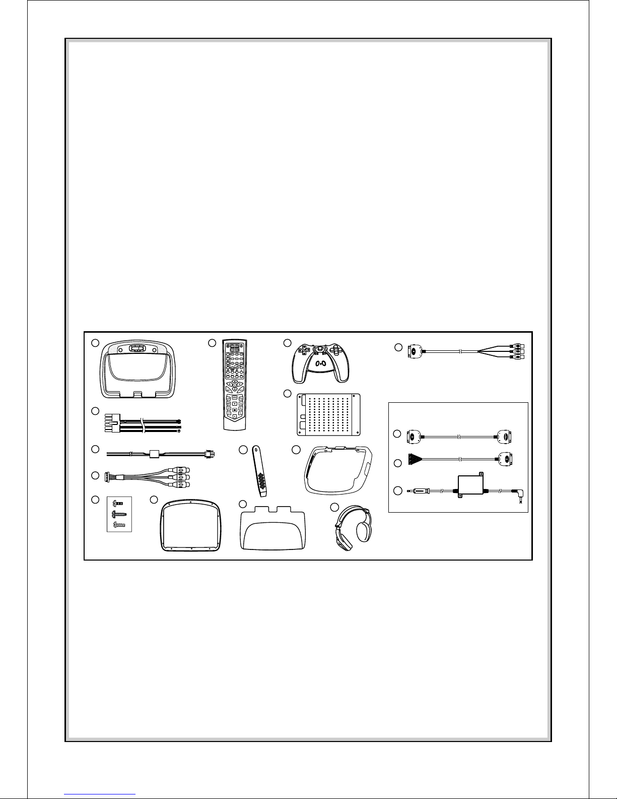
MATERIALS INCLUDED IN THIS PACKAGE:
1) ADV48 TV / Video Monitor with DVD (P/N 136-4423) (1pc)
2) 12 Pin Power / Signal harness (P/N 112-3483) (1pc)
3) 2 Pin Power Wire Harness with choke (P/N 112B3143) (1pc)
4) 9 Pin ~ 3 RCA Jack Pigtail (P/N 112-3682) (1pc)
5) Hardware Package (P/N 150-1674)
Screws ISO 3 x 6mm Long – (10pcs)
#8 x 3/8" Self Drilling Screws – (4pcs)
M5 Screws (4pcs)
6) Trim Ring (Shale) – (1pc), Pewter – (1pc)
7) Remote Control (P/N 136-4427) – (1pc)
8) Wireless Game Controller (P/N 136-4197) (1pc)
9) Mounting Bracket (P/N 108-3930) – (1pc)
10) Pry Tool (P/N 100-2424) (1pc)
11) Snap On Cover (Shroud) ~ Shale (1pc), Pewter (1pc)
12) Snap On Cover (Screen Back Cab) ~ Shale (1pc), Pewter (1pc)
13) Wireless Headphone (P/N MVIRHS) – (2pcs)
14) AUX Cable – (1pc) (P/N 112-3910)
Optional Accessories
15) IPOD Cable – (1pc) (P/N 112-3911)
16) IPOD Hard Wire Cable – (1pc) (P/N 112-3912)
17) SIRSWB Relay Box (P/N 112C3159) (1pc) (Optional) – See important note on previous page
TOOLS REQUIRED:
#2 Phillips Screwdriver
#1 Phillips Screwdriver
Utility or Razor Knife or Shears
Wire Strippers
Upholstery hook tool (for removal of panels as necessary)
Electrical Tape
Masking Tape
Multimeter (to verify 12 volt DC and continuity: Do not use a test light or logic probe)
Marker pen – to mark headliner
Scribe (to mark trim ring if used)
Misc. electrical connectors (to connect to vehicle power source). Requirements will vary
from vehicle to vehicle)
DVD Movie (to verify system operation after installation)
1
(Optional)
2
3
7
10
12
4
16
8
5
13
9
6
11
17
14
15
4
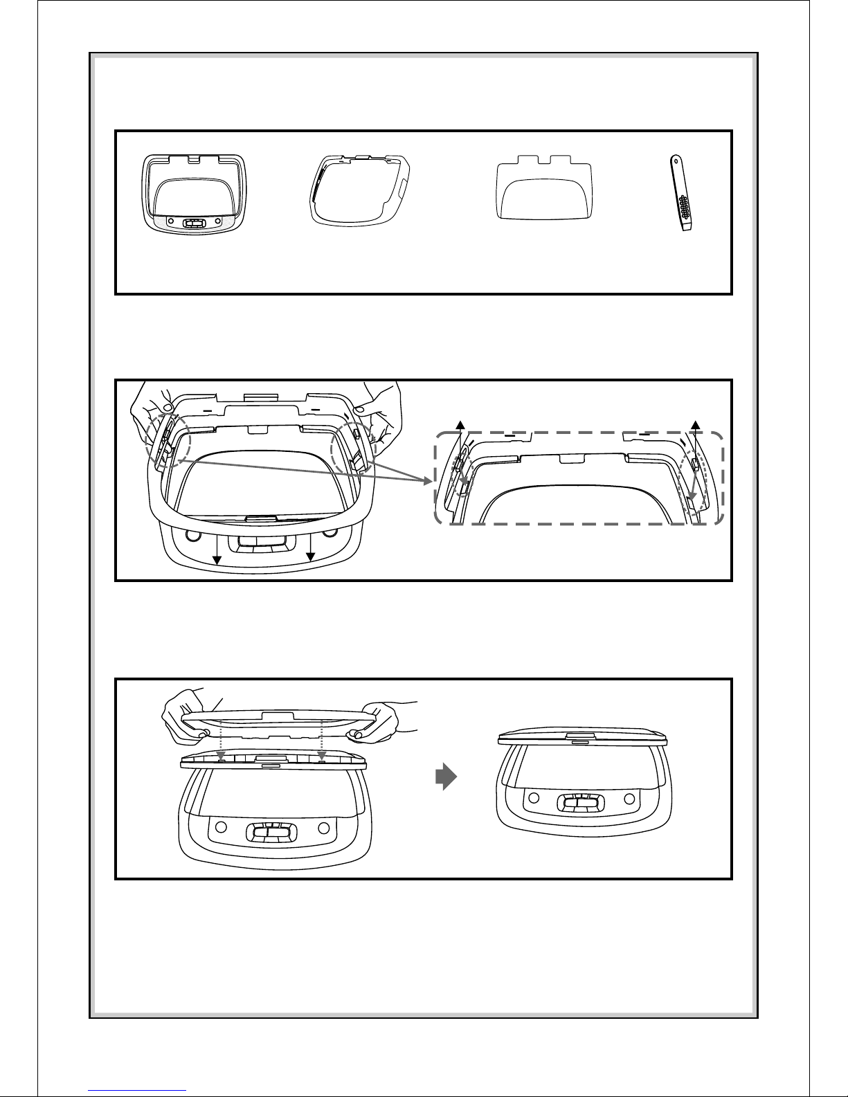
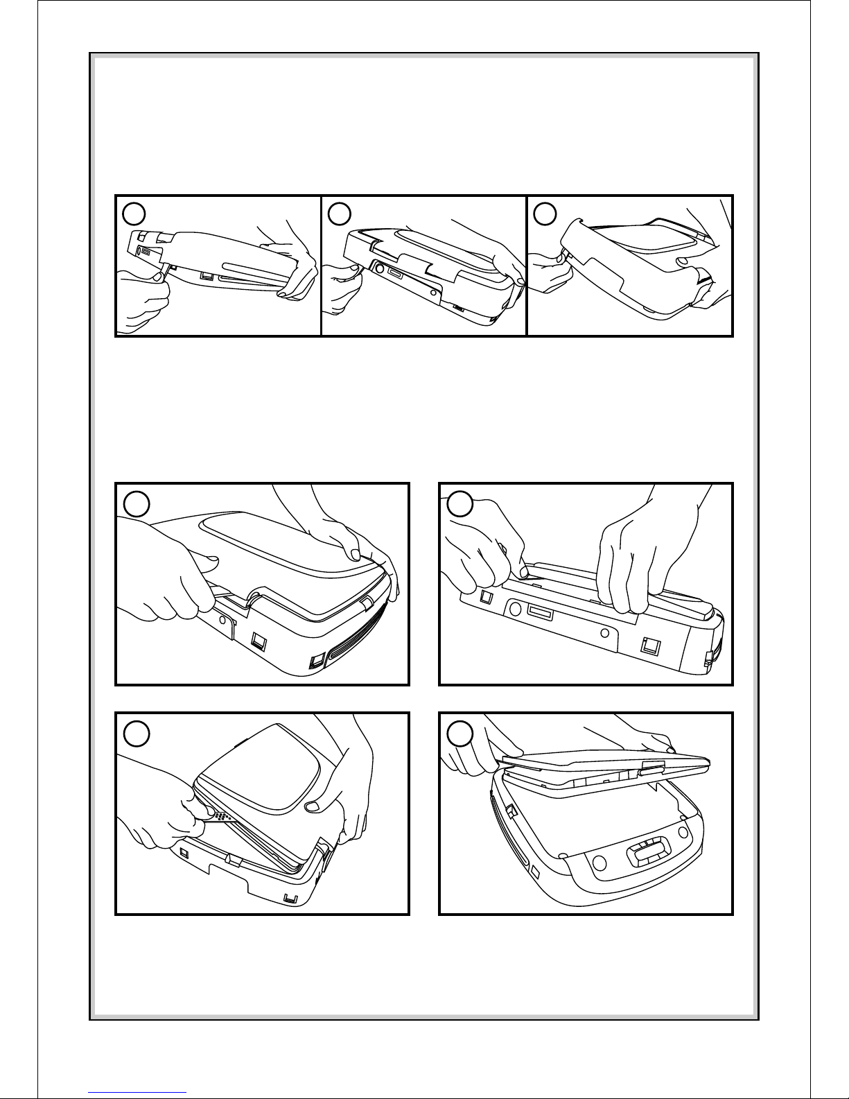
Installing The Snap On Covers
Begin by hooking area “A” (above) over the dome light and slide the cover over the pod. The
cover will snap in place.
catch catch
Installing The Shroud
(A)
Open the screen and hook the two tabs “B” on the bottom edge of the screen. Snap the
opposite side over the hinge
(B)
(B)
Installing The Screen Cover
Place the pod on a soft surface to avoid damaging the plastic.
1. 3.2. 4.
Housing
Snap On Cover
(Shroud)
1 Pewter, 1 Shale
Snap On Cover
(Screen Back Cab)
1 Pewter, 1 Shale
Pry Tool
5
4
Work on a soft surface to avoid damaging the plastic.
Insert the supplied pry tool between the Housing and Snap On Cover (Shroud), then press
the pry tool to release the Snap On Cover (Shroud).
Removing The Snap On Cover (Shroud) From The Housing
Insert the supplied pry tool between the Housing and Snap On Cover (Screen Back), then
press the pry tool to release the Snap On Cover (Screen Back).
Removing The Snap On Cover (Screen Back) From LCD The Housing
7
6
5
2 31
 Loading...