

Page 1
INSTALLATION INSTRUCTIONS
5. Awl or similar tool
Printed in the U.S.A
50-0263x-001 SERIES 1181310
50-0263x-018 SERIES 1181315
50-0263x-019 SERIES 1181320
CHEVROLET S-10 BLAZER
VIDEO CASSETTE PLAYER HOUSING
FOR
These instructions are intended for use only by experienced professionals in the automotive
customizing business. Special tools and equipment, as well as specialized handling and care
of product during installation, may be required. Before beginning this installation, carefully read
through the following instructions.
Materials/ Tools required for this installation:
1. #2 Phillips screwdriver 2. Powered screwdriver or drill with adapter
3. 3/8" drill bit 4. Razor knife or similar
MATERIALS PROVIDED FOR INSTALLATION:
INSTALLATION INSTRUCTION # 44-0027A
6. Audiovox VCP (AVP- 7180 or equiv.)
Jan. 21, 1999
Page 2
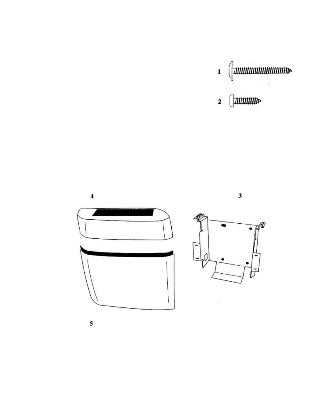
ITEM Description QTY
1
SCREW, # 8 X 1 1/2" PWH 4
2
SCREW, # 8 X 3/4" PPH 4
3
VCP MOUNTING BRACKET 1
4
HOUSING TOP 1
5
HOUSING BOTTOM 1
INSTALLATION INSTRUCTION # 44-0027A
2
Jan. 21, 1999
Printed in the U.S.A.
Page 3

REMOVE AND DISCARD (2) TWO SCREWS WHICH SECURE BRACKET TO
the center of slot on side panel.
metal brace behind plastic panel.
HOUSING.
SEPARATE HOUSING TOP FROM HOUSING BOTTOM.
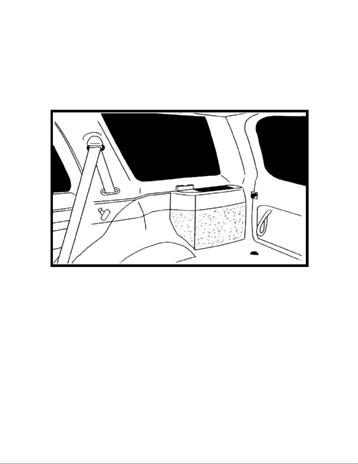
1. Route video and audio cables to passenger’s side
rear of vehicle. Using a razor knife, carefully cut a
slit in carpet to allow cables to pass through. Make
sure wiring will not rub against edge of bracket.
Position VCP mounting bracket (item 3 pg 2)
against side panel and 1 1/8" from back edge of
ledge on side panel as shown. Make sure bottom of
bracket is firmly resting on floor of vehicle. Mark
See Figure 1.
FIGURE 1
2. Carefully drill a 3/8" hole in location previously
marked. CAUTION: Drill through plastic
only, do not drill through sheet metal brace
behind plastic. See Figure 2 .
FIGURE 2
3. Align slot in VCP mounting bracket with hole
previously drilled. Loosely install (1) one
#8 x 1 1/2" screw (item 1 pg 2) in dimple in
FIGURE 3
3
See Figure 3.
Page 4

4. Remove and discard (4) four screws from the side
of VCP. Partially install (4) four #8 x 3/4" screws
(item 2 pg 2). See Figure 4.
FIGURE 4
FIGURE 5
6. Carefully position housing top (item 4 pg 2) on
VCP and slide VCP rearward until housing
contacts plastic panel. Mark position of bracket
and remove housing and VCP. Install (3) three
#8 x 1 1/2" (item 2 pg 2) in holes in bracket and
tighten (1) one screw previously installed.
NOTE: Do not overtighten screws.
See Figure 6.
4
5. Align screws in VCP with slots in bracket and
slide into position. Make sure wiring does not
rub against edge of bracket. See Figure 5.
FIGURE 6
Page 5

FIGURE 7
8. Install housing bottom (item 5 pg 2) and secure to
bracket by inserting clips into slots and pressing
firmly. Make sure contour of housing matches floor
of vehicle prior to securing clips. See
Figure 8.
7. Make all necessary wiring connections to VCP. Check
function of VCP and video system. See operating
instructions included with components. For further
assistance, refer to the video system manual for the
technical support phone number listed for your area.
Install VCP and tighten screws. Make sure VCP
screws are positioned at bottom of slot.
CAUTION: Do not overtighten screws.
See Figure 7.
FIGURE 8
9. Carefully install housing top and press firmly along
bottom edge to secure Velcro tape.
See Figure 9.
FIGURE 9
5
 Loading...