

Page 1
INSTALLATION INSTRUCTIONS
the U.S.A
FOR
50-0244x-001 SERIES 1181275
50-0244x-018 SERIES 1181276
50-0244x-019 SERIES 1181277
CHEVROLET S-10 BLAZER
OVERHEAD CONSOLE for use with FLIPDOWN VIDEO SYSTEM
These instructions are intended for use only by experienced professionals in the automotive
customizing business. Special tools and equipment, as well as specialized handling and care
of product during installation, may be required. Before beginning this installation, carefully read
through the following instructions. Use extreme care when cutting headliner material.
Check for wiring or other componentry above headliner material. Cut only where indicated.
Materials/ Tools required for this installation:
1. #2 Phillips screwdriver 2. Powered screwdriver or drill with adapter
3. T-15 TORX bit driver 4. Razor knife or similar
5. Awl or similar tool 6. 1/4” hex socket bit
7. Band saw or similar 8. Audiovox Series 640/650 Video Module
INSTALLATION INSTRUCTION # 44-0025C
Printed in
June 3, 1999
Page 2
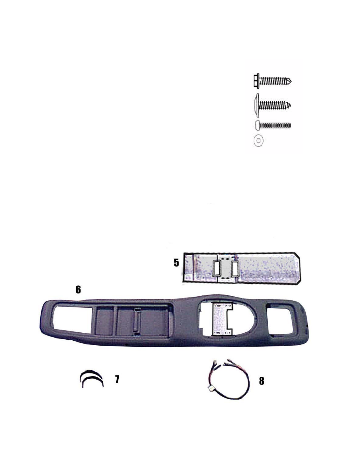
MATERIALS PROVIDED FOR INSTALLATION:
ITEM Description QTY
1
SCREW, # 8 X 3/4" HWH 6
1
2
SCREW, # 8 X 3/4" PWH 4
3
SCREW, 6-32 x 3/4" PPH 4
2
4
5
6
7
8
WASHER, # 6 4
MOUNTING BRACKET 1
CONSOLE 1
FELT TAPE 3/4" X 8" 2
JUMPER HARNESS 1
3
4
INSTALLATION INSTRUCTION # 44-0025C
2
June 3, 1999
Printed in the U.S.A.
Page 3
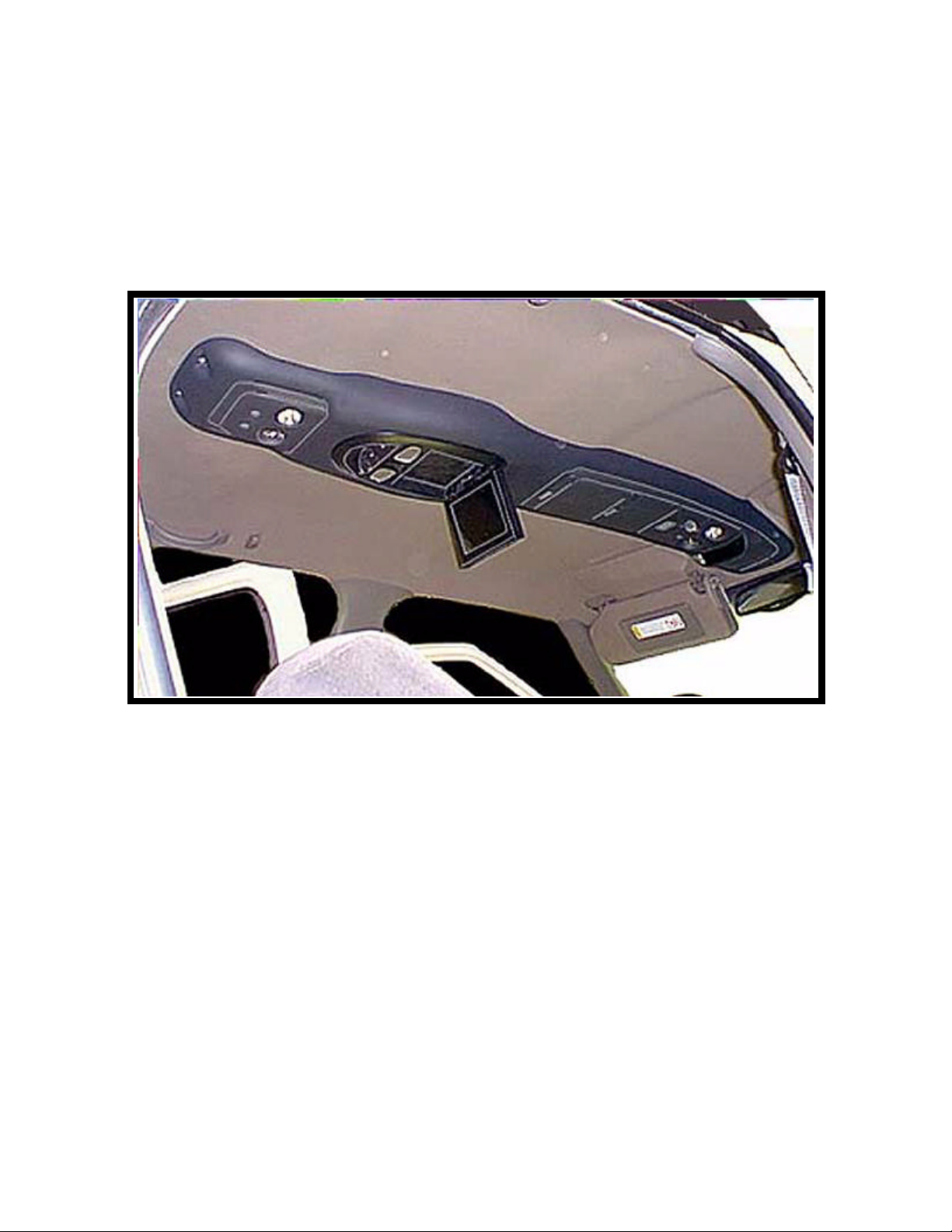
I. PREPARATION OF VEHICLE INTERIOR
O.E.M. screws previously installed.
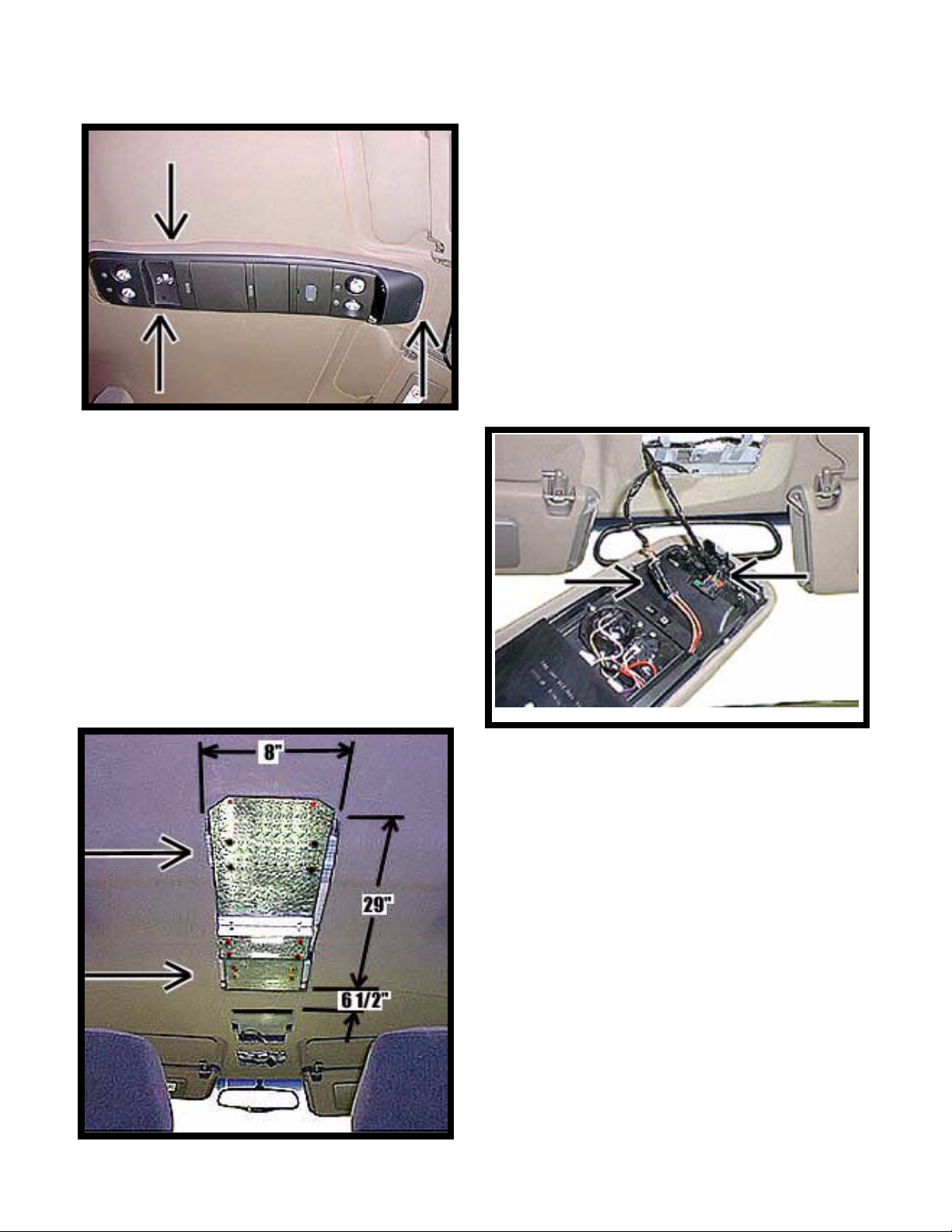
FIGURE 1
2. Lower console and disconnect wiring at (2) two
locations. Lay console on workbench for
modification later.
See Figure 2.
1. Remove the O.E.M. console mounted to inner
roof of vehicle. Remove and discard dome light
cover to gain access to (2) two #8 x 3/4"
screws. Retain screws. Remove and retain (1)
one #8 x 1 1/2" screw located in front of
console near rear view mirror. See Figure 1.
3
FIGURE 3
FIGURE 2
3. Using rear edge of opening in headliner, carefully
trim headliner as shown and install mounting
bracket (item 5 pg 2). Make sure the 8” cut is
centered in vehicle. Caution: Before cutting
headliner material, check for wiring or other
componentry above headliner. Cut only where
indicated. Secure front of bracket to roof brace
using (2) two O.E.M. screws, previously
removed, in original locations. Make sure that
bracket is centered in vehicle and secure rear of
bracket to roof brace using (4) four #8 x 3/4"
screws (item 1 pg 2). Install (2) two #8 x 3/4"
screws (item 1 pg 2) in remaining holes next to
See Figure 3.
Page 4

II. PREPARATION OF CONSOLE FOR INSTALLATION
cloth covered trim ring.
4. Turn console upside down and remove and
retain (15) fifteen T-15 TORX screws which
secure the cloth covered trim ring to console.
See Figure 4.
5. Turn console over and open both
compartment doors. Carefully separate the
console from trim ring. Remove electronic
compass from console and lay it in a safe place
for use later. Remove and retain velcro tape
and lay it in a safe place for later use. Discard
FIGURE 4
FIGURE 5
6. Cut the orange and black wires from dome light.
Cut all wires 7” from tape where indicated.
See Figure 6.
See Figure 5.
FIGURE 6
4
Page 5

FIGURE 7
8. Install the electronic compass in original position
and secure using (2) two pieces of felt tape (item 7
pg 2). See Figure 8.
7. Mark a line on both sides of dome light as
close to the edge as possible. Using a band
saw or suitable tool, carefully trim console as
shown. Discard dome light. Note: If console
is trimmed too far away from dome light,
the trimmed edge may be visible when
installed in vinyl console. See Figure 7.
Installer’s option: Turn console over and place
on a padded surface. Trim console along ridge
on either side of dome light.
FIGURE 8
5
Page 6

e opening in center of console.
FIGURE 9
10. Carefully turn console over and secure
O.E.M. console using original screws. Start
all screws before tightening. Caution: Do
not overtighten screws. See Figure 10.
11. Install jumper wire harness (item 8 pg 2) to
extend the red, violet, orange, and black
wires previously cut on O.E.M. harness.
Connect the white wires from video system
light to orange O.E.M. wire. Connect the
black wires from video system light to
black O.E.M. wire. Firmly crimp wires then
slide shrink sleeve over butt connector and
apply heat.
9. Carefully insert modified console into vinyl
covered console as shown. Insert the video
system in th
See Figure 9. Note: Leave
compartment door open to the 90 degree
position until console is installed in
vehicle. This will allow access for
installing screws. If the door is closed
prior to installation in vehicle, it will not
open enough to properly install screws.
CAUTION: The edges of O.E.M. console
may be sharp and could cut the vinyl
console during installation. It may be
necessary to deburr the edge of console
before installation.
FIGURE 10
6
Page 7

two #8 x 3/4" screws (item 2 pg 2). See Fig. 12.
32 X 3/4" screws previously
III. INSTALLATION OF CONSOLE
NOTE: Additional assistance in mounting the overhead console in vehicle is
advised to prevent damage to console or components.
12. Install and route all video and audio cables, and
any other added component requirements to
their respective places in the vehicle. Refer to
component installation instructions for wiring
diagrams. The suggested routing of the video
system cable is as follows: Above the headliner
from video system to B-pillar. Rearward to the
C-pillar. Down the C-pillar to the floor. Route
the power lead to an accessory controlled
source. Connect the ground lead to the vehicle
chassis. Route the remaining wiring (RCA
plugs, Remote Sensor extension, etc.) to the
VCP location. See Figure 11. Connect per
instructions included with the video system. If
video system if to be used as a television, install
an appropriate antenna per instructions
included with the antenna.
FIGURE 11
Caution: Do not overtighten screws. Use extra support for the console until secured to the
vehicle. Failure to do so may cause damage to console or installed components.
13. Raise console into approximate position and connect wiring to O.E. components.
14. Carefully position console against headliner.
Loosely install using (2) two 6-32 X 3/4"
screws (item 3 pg 2) through the smaller holes
in bracket on console into threaded clips on
mounting bracket.
15. Secure the front of console to the inner roof of
vehicle using original screw in original location.
See Figure 12.
16. Using an awl or similar tool, align the rear
mounting holes with holes in bracket. Apply
upward pressure to console and secure using (2)
FIGURE 12
7
17. Tighten (2) two 6-
installed in step 14.
Page 8

18. Release video screen from locked position. Lower video screen to viewing position for access to
mounting locations in top of video system
housing.
19. Raise video system into approximate position
and connect all wiring to components. Route
video cable through hole in mounting bracket.
Connect wiring and cabling to video system
per instructions included with video system.
20. Check function of all components and lights.
See operating instructions for video system
operations check. For further assistance, refer
to the video system manual for the technical
support phone number listed for your area.
21. Insert video system into opening in console.
Note: Make sure that wires do not get
pinched between bosses on video system and
console. Align holes in housing with clips in
FIGURE 13
mounting bracket. Loosely install (4) four
6-32 X 3/4" screws (item 3 pg 2) and (4) four
3.5mm washers (item 4 pg 2). Caution:
Do not overtighten screws. See Figure 13.
22. Raise video screen into locked position.
23. Through the open compartment door on
O.E.M. console, use an awl or similar tool to
align holes in console with holes in bracket.
Secure using (2) two #8 x 3/4" screws (item 2
pg 2). See Fig. 14. Close compartment door.
24. If console was equipped with a Homelinktm
Transmitter, refer to the vehicle owner’s
manual for reprogramming instructions.
FIGURE 14
8
 Loading...