

Page 1

ADC700
POWER INVERTER
Owner’s Manual
Page 2

TABLE OF CONTENTS
1. INTRODUCTION ............................................................................3
2. HOW YOUR AUDIOVOX ADC700 WORKS ................................. 4
Operation ....................................................................................4
Audiovox ADC700 Output Waveform...................................... 5
3. INSTALLA TION...............................................................................6
Power Source Requirements................................................. 6
Connection to Power Source .....................................................7
Connection to Load ............................................................... 7
Fuse Replacement..................................................................8
Placement of the ADC700..........................................................9
4. OPERATING TIPS..........................................................................10
Rated Versus Actual Current Draw of Equipment .....................10
Battery Operating Time ..............................................................11
5.TROUBLESHOOTING ....................................................................11
Protective Features of the ADC700...........................................11
Common Problems.....................................................................12
Troubleshooting Guide ...............................................................13
2
Page 3

1. INTRODUCTION
Y our new Audiovox ADC700 inverter is one in a series of the most advanced
DC to AC inverters available today. With proper care and appropriate usage, it will give you years of dependable service in your car, truck, RV, boat
or even airplane.
The ADC700 supplies 700 Watts of continuous power, with a 1400 Watt
peak, in the form of a household-type outlet that is ready to deliver 110-volt
AC power whenever and wherever you need it! Simply connect the inverter
to the vehicle battery to run almost any small household or electronic appliance including: color TVs (up to 21"); VCRs; portable radios/boom boxes;
laptop computers; camcorder, cellular phone and power tool chargers; lamps
(up to 700 watts); light duty power tools (up to 1.75A); and many more. The
ADC700 AC receptacle is fully polarized, weatherproof and fused. Added
safety features include automatic
prevent damage to your battery.
To ensure a long duration of reliable service, your power inverter must be
installed and used properly. Please read the installation and operating instructions thoroughly prior to installation and use. Pay particular attention to
the CAUTION and WARNING statements in this manual. The CAUTION
statements advise against certain conditions and practices that may result
in damage to your ADC700. The WARNING statements identify conditions
or practices that may result in personal injury or loss of life.
shutdown
and a low battery alarm to
3
Page 4

2. HOW YOUR AUDIOVOX ADC700 INVERTER WORKS
The ADC700 inverter is an electronic device that converts low voltage DC
(direct current) electricity from a battery or other power source to standard
115 volt AC (alternating current) household power . In designing the ADC700,
Audiovox has incorporated design techniques previously employed in computer power supplies. The result of these design innovations is a smaller,
lighter and easier-to-use power inverter.
OPERATION
The ADC700 inverter converts power in two stages. The first stage is a
DC-to-DC conversion process that raises the low voltage DC at the inverter
input to 145 volts DC. The second stage is the actual inverter stage that
converts the high voltage DC into 115 volts, 60 Hz AC.
The DC-to-DC converter stage uses modern high frequency power conversion techniques that have replaced the bulky transformers found in less
technologically-advanced models. The inverter stage uses advanced power
MOSFET transistors in a full bridge configuration. This ensures excellent
overload capability and the ability to operate reactive loads like lamp ballasts and small induction motors.
4
Page 5
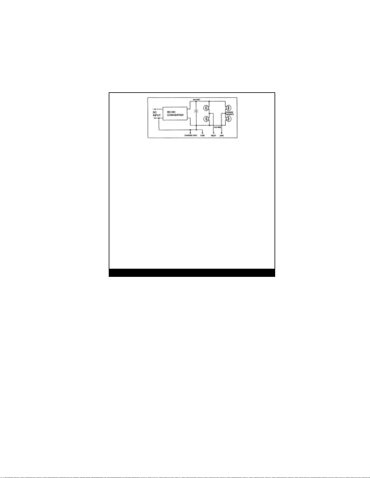
Figure 1. Audiovox ADC700 Inverter Operation
ADC700
The AC output waveform of the ADC700 is known as a “quasi-sine wave” or
a “modified sine wave”. It is a stepped waveform that is designed to have
characteristics similar to the sine wave shape of utility power. This type of
waveform is suitable for most AC loads, including linear and switching power
supplies used in electronic equipment, transformers, and motors.
The modified sine wave produced by the ADC700 inverter is designed to
have an RMS (root mean square) voltage of 115 volts, which is the same as
standard household power. Most AC voltmeters (both digital and analog) are
sensitive to the average value of the waveform rather than the RMS value.
They are calibrated for RMS voltage under the assumption that the waveform measured will be a pure sine wave. These meters will not read the RMS
voltage of a modified sine wave correctly. They will read about 20 to 30 volts
low when measuring the output of the ADC700. For accurate measurement
of the output voltage of this unit, use a true RMS reading voltmeter such as a
Fluke 87, Fluke 8060A, Beckman 4410, or a Triplett 4200.
Output Waveform
5
Page 6

Figure 2. ADC700, Modified Sinewave
3. INSTALLATI0N
Power Source Requirements
The power source must provide between 11 and 15 volts DC and must be
able to supply the necessary current to operate the load. The power source
may be a battery or a well-regulated DC power supply. To obtain a rough
estimate of the current (in amperes) the power source must deliver; simply
divide the power consumption of the load (in watts) by 10.
Example: If a load is rated at 100 watts, the power source must be able to
deliver:
100 ÷ 10 = 10 amperes
CAUTION: The ADC700 must be connected only to batteries with a
6
nominal output voltage of 12 volts. The unit will not operate
from a 6-volt battery and will sustain permanent damage if
connected to a 24-volt battery.
Page 7

CONNECTION TO POWER SOURCE
The ADC700 comes with positive and negative wires and clamps (Red = +,
Black = -) which are to be connected directly to the vehicle battery.
CAUTION: Reverse polarity connection will result in damage to the
Inverter.
If the inverter is connected to the incorrect polarity, the fuse will be blown. If
the unit does not function after replacement of the fuse, the unit must be
returned to Audiovox for repair. Repair expenses for this type of damage
are not covered by your warranty.
CAUTION: Do Not Use with positive ground electrical systems. (The
majority of modern automobiles, RVs, and trucks are negative
ground.
CONNECTION TO LOAD
The ADC700 is equipped with a standard AC household-type receptacle.
Plug the cord from the equipment you wish to operate into the AC receptacle. The green LED indicator will illuminate to indicate that the unit is
functioning. Make sure the load requirements of your equipment are within
the parameters of the ADC700 output. If so, turn on your equipment. If an
audible alarm sounds, refer to sections 2, 3 or 4 of this manual for probable
causes.
7
Page 8

DO NOT CONNECT TO AC DISTRIBUTION WIRING
The
ADC700
and electronic equipment in the manner described above. Do not connect
the Power Inverter to household or RV AC distribution wiring. Do not connect the Power Inverter to any AC load circuit in which the neutral
conductor is connected to ground (earth) or to the negative of the DC (battery) source.
CAUTION: Rechargeable Appliances!
Certain rechargeable devices are designed to be recharged by plugging
them directly into an AC receptacle. These devices may damage the
ADC700. When first using a rechargeable device, monitor its temperature
for the initial 10 minutes of use to determine whether it emits excessive
heat. If excessive heat is detected, it is a good indication that the device
should not be used with this inverter. This problem does not occur with the
majority of battery-operated equipment. Most of these devices use a separate charger or transformer that is plugged into an AC receptacle. The
ADC700 is easily capable of running most chargers and transformers.
is engineered to be connected directly to standard electrical
FUSE REPLACEMENT
If the ADC700 is overloaded and the spade type fuse (s) (35A) is blown,
flip up the fuse (s) replacement cover on the back of the ADC700 and
replace the blown fuse (s) with a new spade type, 35 Amp fuse. Determine
the cause of the short before restarting your ADC700 again.
8
Page 9

PLACEMENT OF THE ADC700
For best operating results, the inverter should be placed on a flat surface,
such as a vehicle seat or floor. A power cord measuring 3 feet (1.0 meter)
has been provided for easy positioning of the inverter. ADC700 should only
be used in locations that meet the following criteria:
DRY: Do not allow water or other liquids to come into contact with the
ADC700 inverter.
COOL: Ambient air temperature should be between -20° C and 40° C
(ideally between 15° C and 25° C (60 - 80° F). Do not place the
inverter on or near a heating vent or any piece of equipment
which is generating heat above room temperature. Keep the in
verter away from direct sunlight, if at all possible.
VENTILATED: Keep the area surrounding the ADC700 clear to ensure
free air circulation around the unit. Do not place items on or over
the inverter during operation. A fan is helpful if the inverter is op
erating at maximum power outputs for extended periods of time.
The unit will shut down if the internal temperature exceeds 90° C.
Restart the unit once it cools down sufficiently.
SAFE: Do not use the ADC700 near flammable materials or in any
locations that may accumulate flammable fumes or gases.
9
Page 10

4. OPERATING TIPS
Rated versus Actual Current Draw of Equipment
Most electrical tools, appliances and audio/video equipment have labels
that indicate the power consumption in amps or watts. Be sure that the
power consumption of the item you wish to operate is rated at 700 watts or
less. (If the power consumption is rated in amps, simply multiply by the AC
volts (115) to determine the wattage). The inverter has overload protection,
so it is safe to try to operate equipment rated at 700 watts or less. The
inverter will shut down if is overloaded, and will restart once the overload is
rectified.
Resistive loads are the easiest for the ADC700 to run; however, larger resistive loads, such as electric stoves or heaters, usually require more wattage than the ADC700 can deliver on a continuous basis. Inductive loads,
such as TV’s and stereos, require more current to operate than do resistive
loads of the same wattage rating. Induction motors, as well as some televisions, may require 2 to 6 times their wattage rating to start up. The most
demanding in this category are those that start under load, such as compressors and pumps. Testing is the only definitive way to determine whether
a specific load can be started and how long it can run. The unit will simply
shut down if it is overloaded. To restart the unit after a shutdown due to
overloading, momentarily turn off the power to the unit.
NOTE: The ADC700 will not operate appliances and equipment that
10
produce heat, such as hair dryers, microwave ovens and
toasters.
Page 11

BATTERY OPERATING TIME
With a typical vehicle battery, a minimum operating time of 2 to 3 hours can
be expected. In most instances, 5 to 10 hours of operating time is achievable. However, Audiovox recommends that the operator start the vehicle
every 2 to 3 hours to recharge the battery system. This will guard against
any unexpected shutdowns of the equipment and will ensure that there is
always sufficient battery capacity to start the vehicle’s engine.
The inverter may be used whether or not the vehicle’s engine is running.
However, the inverter may not operate while the engine is starting since the
battery voltage can drop substantially during cranking.
The ADC700 Power inverter draws less than 0.6 ampere from the battery
when it is not supplying power to a load.
5. TROUBLESHOOTING
Protective Features of the
Your ADC700 monitors the following potentially hazardous conditions:
Low Battery Volt age - This condition is not harmful to the inverter but could
damage the power source. An audible alarm will sound when input voltage
drops to a range of 11.5 to 10.5 volts. The ADC700 automatically shuts
down when input voltage drops to a range of 10.5 to 9.8 volts. When the
condition is corrected, the unit may be restarted.
Over Voltage Protection - The ADC700 will automatically shut down
when the input voltage exceeds 15 volts DC.
Short Circuit Protection - Reverse polarity or a short circuit condition will
usually result in the fuse being blown. Immediately disconnect the shorted
load and replace the fuse inside the plug of the ADC700 as described in
Section 3.
ADC700
11
Page 12

Overload Protection - The inverter will automatically shut down when the
continuous draw exceeds 700 watts.
Over Temperature Protection - When the temperature sensor inside the
ADC700 reaches 150°F, the unit will automatically shut down. Allow the unit
to cool for at least 15 minutes before restarting after a heat-related shutdown. Unplug unit while cooling.
CAUTION: Low Battery Alarm
An alarm will sound when the voltage from the battery drops to 11.5 volts.
This is an indication that the battery needs to be recharged. The user
should stop operation of the electronic device at this time since the ADC700
will shut down automatically shortly thereafter, when the battery voltage
drops to 9.8 volts.
COMMON PROBLEMS
“Buzzing” sound in audio systems
Some inexpensive stereo systems and “boom boxes” emit a buzzing sound
from their speakers when operated from the ADC700 power inverter. This
occurs because the power supply in the electronic device does not adequately filter the modified sine wave produced by the ADC700. The only
solution to this problem is to use a sound system that incorporates a higher
quality power supply.
12
Page 13

Television Interference
The Audiovox ADC700 is shielded to minimize interference with TV signals.
However, in some instances, some interference may still be visible, particularly with weak TV signals. Try the following corrective measures:
Position the ADC700 as far as possible from the television, the antenna
and the antenna cables. Use an extension cable, if necessary.
Adjust the orientation of the ADC700, the antennae cables and the TV
power cord to minimize interference.
Make sure that the, antenna connected to the television provides an
adequate (“snow free”) signal and that high quality, shielded antenna cable
is used.
TROUBLESHOOTING GUIDE:
PROBLEM: LACK OF OUTPUT
Possible Causes Suggested Solution
Inverter not adequately warmed Turn inverter power switch
up. OFF and then ON again.
Repeat if necessary.
Battery voltage below 10.4 volts. Recharge or replace battery.
Equipment being operated draws Reduce load to maximum
too much power. 700 watts.
13
Page 14

PROBLEM: LACK OF POWER OUTPUT (Cont)
Inverter in thermal shutdown condition. Allow inverter to cool down.
Ensure there is adequate
ventilation around unit. Ensure
that load is no more than 700
watts for continuous operation.
Inverter fuse blown. Replace inverter is connected
PROBLEM: LOW OUTPUT VOLTAGE
Possible Causes Suggested Solution
Using average reading voltmeter. Use true RMS reading meter.
Inverter is overloaded. Reduce load to 700 watts maxi-
Input voltage below 10.4 volts. Keep input voltage above 10.4
14
fuse. Be sure the to a power
source with correct voltage and
polarity.
mum to maintain regulation.
volts to maintain regulation.
Page 15

PROBLEM: LOW BATTERY ALARM SOUNDS CONTINUOUSLY
Possible Causes Suggested Solution
Poor battery condition. Replace battery
Inadequate power or excessive voltage Clean battery terminals and
replace if necessary.
15
Page 16

AUDIOVOX ADC700 POWER INVERTER PRODUCT SPECIFICATIONS
Maximum Continuous Power ..................... 700 Watts
Surge Capacity (Peak Power) ................... 1400 Watts
Maximum Efficiency...................................Approx 82% or above (no-load
No-Load Current Draw .............................. 0.6A
Input Voltage Range................................... 10.4-15.5Vdc
Low Voltage Shutdown Activation.............10. 4 Volts
Low Voltage Alarm Activation................... 11.5 Volts
Waveform ................................................... Modulated Sinewave
NO. of AC Receptacles ............................. Two
Fuse ............................................................35 Amp
Weight ........................................................ 3.2 Lbs (1.418 Kg)
Length........................................................9 3/4” (245 mm)
Width .......................................................... 6 1/4 ” (156 mm)
Heigh .......................................................... 2.0” (50 mm)
16
current)
 Loading...