

Page 1
INSTALLATION INSTRUCTIONS
FOR
55-0401x-121 SERIES 1187001PL
2001 DURANGO
OVERHEAD CONSOLE for use with FLIPDOWN VIDEO SYSTEM
These instructions are intended for use only by experienced professionals in the automotive
customizing business. Special tools and equipment, as well as specialized handling and care
of product during installation, may be required. Before beginning this installation, carefully read
through the following instructions.
Check for wiring or other componentry above headliner material. Cut only where indicated.
Materials/ Tools required for this installation:
1. #2 Phillips screwdriver 2. Powered screwdriver or drill with adapter
3. Awl or similar tool 4. Digital Volt Meter
5. 18 GA wire 9' 6. Rubbing Alcohol
7. 5/16” Hex Socket Bit 8. Razor knife or similar
9. Pencil or equivalent 10. Measuring tape
11. Masking tape 12. Audiovox Video Module
NOT FOR VEHICLES EQUIPPED WITH SUN ROOF.
128-6067
INSTALLATION INSTRUCTION # 44-0091A
Use extreme care when cutting headliner material.
Feb. 13,2001
Printed in the U.S.A
Page 2
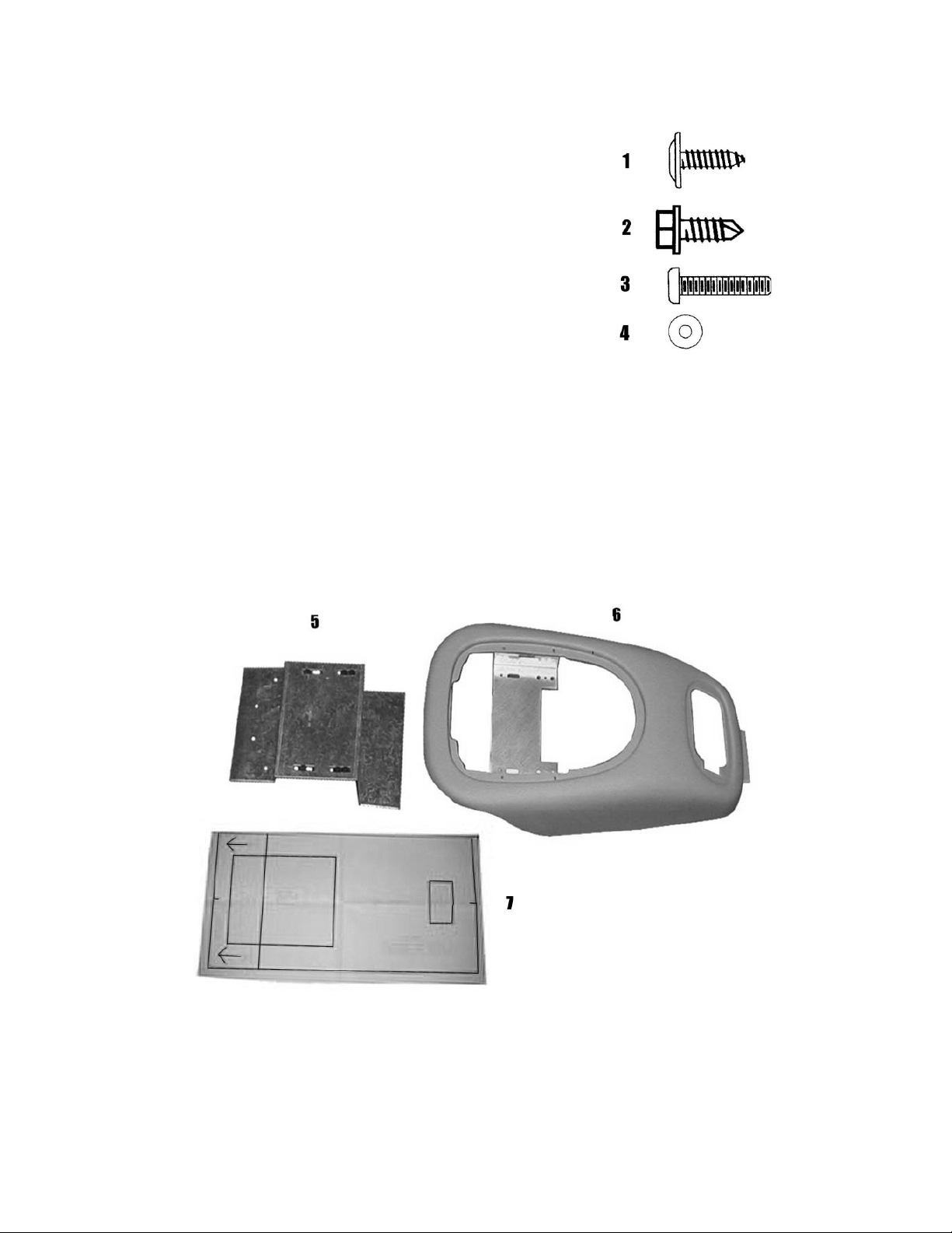
MATERIALS PROVIDED FOR INSTALLATION:
ITEM Description QTY
1
2
3
4
5
6
7
SCREW, #8 X 9/16" PWH 2
SCREW, # 10 X 1/2" HWH,TEK 2
SCREW, 6-32 X 3/4" ,PPH 6
WASHER, 3.5 mm 4
MOUNTING BRACKET 1
CONSOLE 1
TEMPLATE 1
INSTALLATION INSTRUCTION # 44-0091A
Feb. 13,2001
Printed in the U.S.A.
2
Page 3

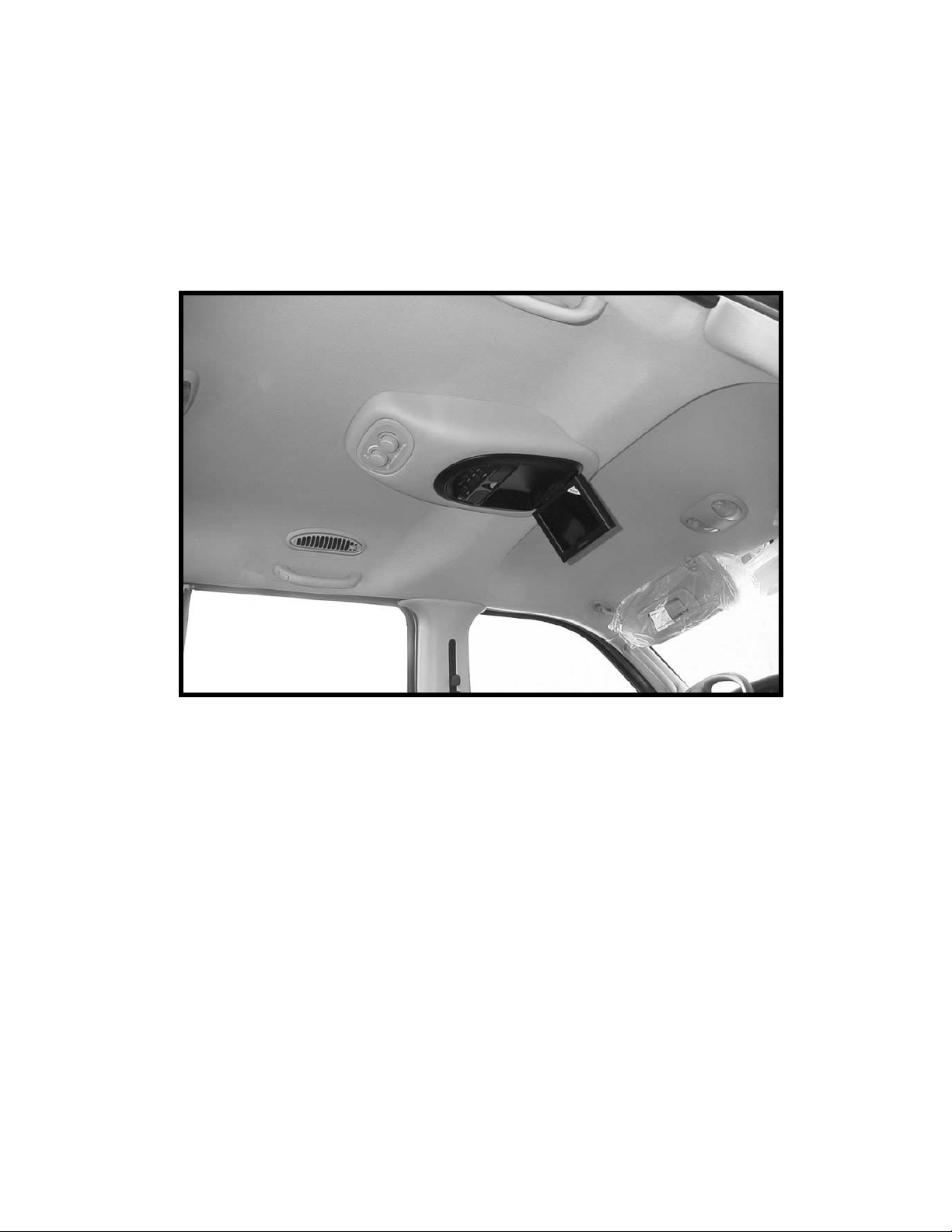
I. PREPARATION OF VEHICLE INTERIOR
FIGURE 1
2. Cut template (item 7 pg 2) in area #1. Locate and
tape template to the headliner. Make sure
template is centered left to right in vehicle and
mark area to be cut. Remove template and trim
headliner. Cut template areas #2 & #3 and
reinstall the template to the headliner. Ensure area
#1 of the template hole locations are aligned with
the OEM bracket holes. Mark and trim headliner
The rear cutout is critical, do not overcut or
the opening will be visible when the console is
installed. See Fig. 2. Caution: Before cutting
headliner material, check for wiring or other
componentry above headliner. Cut only where
indicated.
1. Remove and retain rear A/C controls by pulling
downward. Disconnect wire harness. See Figure 1.
Set controls in a safe place for reuse later.
.
FIGURE 2
FIGURE 3
3. Remove and retain O.E. A/C switch bracket and
screws. See Figure 3.
3
Page 4

4. Carefully pull (3) A/C wire harness clips from roof
brace to extend length of wire harness. It may be
necessary to lower the driver’s side of headliner at
the “B” pillar to gain access to the 3rd clip. See Fig. 4
Use caution when pulling on wire harness and
pulling downward on headliner. The connector
should reach the rear cut-out in headliner when all
clips are released.
FIGURE 5
FIGURE 4
5. Install and route all video and audio cables, and any
other added component requirements to their
respective places in the vehicle. Refer to component
installation instructions for wiring diagrams. The
suggested routing of the video system cable is as
follows: Above the headliner from video system to
the C-pillar. Down the C-pillar to the floor. Route
the power lead to a fused accessory controlled
source. Connect the ground lead to the vehicle
chassis. Route the remaining wiring (RCA plugs,
Remote Sensor extension, etc.) to the VCP location.
See Figure 5. Connect per instructions included with
the video system. If video system if to be used as a
television, install an appropriate antenna per
instructions included with the antenna.
6. Using a digital volt meter, check function of lights.
7. Construct a 3' jumper harness that will connect the
vehicle’s dome light wires to the lights in video
system. Connect the red/black wire from video system
to the O.E. yellow/purple wire. Connect the purple
wire from video system to the O.E. yellow wire.
Connect the black wire from video system to the
O.E. pink wire. See Fig. 6.
4
FIGURE 6
Page 5

8. Remove and retain mounting bracket and screws
(items 5&3 pg2) from console (item 6 pg2). Use
rubbing alcohol to clean sheet metal in the cut–out
area in headliner. Wipe surface dry with a clean
cloth. Remove protective tape from adhesive
strips on mounting bracket (item 5 pg2).
sure bracket is centered prior to pressing tape
against roof surface. Once the tape is applied
to the roof, DO NOT REMOVE AND
REPOSITION or the tape will not stick
properly.
(item 2 pg2). See Figure 7.
FIGURE 7
original holes and (2) two # 10 x 1/2" TEK screws
Install using (2) two O.E. screws in
Make
9. Install A/C switch into rear of console (item 6 pg2)
and O.E. bracket over A/C switch. Make sure control
snaps securely into bracket. See Figure 8.
10. Secure bracket to console brace using (2) two # 8 x
9/16" screws (item 1 pg 2). See Figure 8.
FIGURE 8
5
Page 6

FIGURE 9
II. INSTALLATION OF CONSOLE
11. Raise console (item 6 pg 2) into approximate
position against headliner. Connect O.E. wiring
to A/C control.
12. Insert plastic flange on rear of console into
opening in headliner. Make sure console is
centered left to right. See Figure 9.
13. Secure console secure front of console using (2)
two 6-32 x 3/4" screws (item 3 pg 2).
14. Release video screen from locked position.
Lower video screen to viewing position for
access to mounting locations in top of video
system housing.
15. Raise video system into approximate position
and connect all wiring to components. Connect
wiring and cabling to video system per
instructions included with video system.
16. Check function of all components and lights. See
operating instructions for video system
operations check. For further assistance, refer to
the video system manual for the technical
support phone number listed for your area.
17. Insert video system into opening in console.
system and console.
Align holes in housing with holes in mounting bracket. Secure using (4) four 6-32 x
Note: Make sure wires do not get pinched between video
3/4"screws and (4) four 3.5 mm washers (items 3&4 pg2). See Figure 10.
Caution: Do not overtighten screws.
18. Raise video screen into locked position.
FIGURE 10
6
 Loading...