

Page 1
Description of CS (Control Station)
3
MAIN
POWER
1
5
VOLUME
2
IR
3
4
1
®
ELECTRONICS CO RP.ELECTRONICS CO RP.
4
CS
6
Control Station
S
2
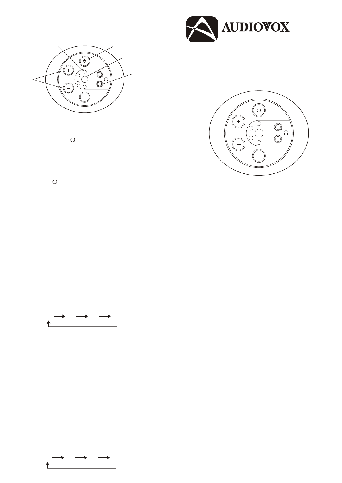
1. System Power Button
MAIN POWER ( ) button
– Press to turn the Control Station on. The
LED indicators and 1 source LED indicator
will illuminate.
– Press to turn the Control Station off. The
LED indicators will turn off and the MAIN
POWER ( ) (1) will dimmed.
128-6055
2. Source Select Control Button
– Press the source SELECT (S) button (2) to
step through the different Audio/Video Input
Sources, each press button of the SELECT
(S) button (2) will advance to the next input
source. The source indicator LED (3) will light
in the following sequences:
3. Source Indicator LED
– Indicates the video source that can will be
viewed.
4. Remote Sensor Eye
– When the source indicator LED (3) is
flashing, this indicates that the source
equipment can be controlled remotely by
pointing the remote control device at the
S1 S2 S3 S4
remote device sensor.
5. Volume Up/Down Button
– Press the “+” button to increase headphone
– Before attempting to operate the Remote
Control, press and hold the source SELECT
button (2) for 6 seconds until the source
indicator LED (3) begins flashing. Once the
indicator is blinking the Control Station will
accept Infrared input command signals from
an Infrared Remote Control device. To
remove the Infrared Control function from the
Control Station press and hold the button for
3 seconds.
volume.
– Press the “–” button to decrease headphone
volume.
6. Headset (3.5mm Headphone jacks)
– These jacks provide connections for stereo
headphones for private listening at each
station. (Note: Plug the headphones in before
putting the headphones on. Adjust the
volume to a low level before putting the
headphones on.)
– If source indicator LED (3) is blinking the
S1 position, the Control Station has selected
to control the Audio/Video Input at Source 1.
To change the sources, press the source
SELECT button (2) to view the following
sources.
MAIN
POWER
1
2
VOLUME
IR
3
4
S
Owner’s Manual
S1 S2 S3 S4
Page 2
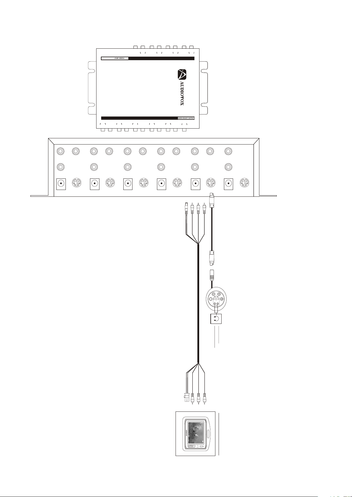
Installation from SDB to CS
MONITOR 5
DC 12V
STATION 5
CONTROLLER
STATION 5
AUDIO
L R
MONITOR 4
DC 12V
CONTROLLER
STATION 3
STATION 4
AUDIO
VIDEO
L R
STATION 4
POWER INPUT
A/V SELECT OUTPUT
AUDIO
VIDEO VIDEO
L R
MONITOR 3
DC 12V
L R
VIDEO 4
4
AUDIO
STATION 2
AUDIO
L R
STATION 3
CONTROLLER
L R
VIDEO 3
VIDEO 2
3
AUDIO
A/V SOURCE INPUT
SIGNAL DISTRIBUTION BOX
MODEL : SDB
STATION 1
AUDIO
VIDEO
L R
MONITOR 2
DC 12V
L R
2
AUDIO
AUDIO SELECT OUTPUT
VIDEO
STATION 2
CONTROLLER
®
MASTER
STATION
AUDIO
L R
VIDEO 1
MONITOR 1
DC 12V FROM SDB45CSVIDEO (YELLOW)
1
AUDIO
DC 12V
L R
SDB
FM MODULATOR
DC 12V
AUDIO RIGHT (RED)
STATION 1
CONTROLLER
AUDIO LEFT (WHITE)
DIN CABLE, SDB TO CS (P/N:CSDIN)
MASTER
CONTROLLER
HARNESS, SDB TO MONITOR (P/N:CSSC)
VOLUME
3
2
S
4
1
IR
POWER
MAIN
HEADPHONE
OPTIONAL
AUDIO RIGHT (RED)
AUDIO LEFT (WHITE)
POWER
VIDEO (YELLOW)
OPTIONAL AV MONITORS
PICTURE
POWER
SELECT
IR
 Loading...