

Page 1
OWNER'S MANUAL
ACD-75
AM/FM/MPX RADIO
WITH DETACHABLE FRONT PANEL,
COMPACT DISC PLAYER,
CD CHANGER CONTROLS
AND QUARTZ CLOCK
Page 2

INSTALLATION INSTRUCTIONS
This unit is designed for installation in GM and Chrysler cars, trucks, and vans with a 1-1/2 DIN
IONSIONS
IONSIONS
IONS
TT
TT
T
radio opening. In some cases, a special installation kit will be required to mount the radio to the
dashboard. These kits are available at electronics supply stores and car stereo specialty shops.
Always check the kit application before purchasing to make sure the kit works with your vehicle.
If you need a kit but cannot find it available, call our toll-free “HELP” line at 1-800-645-4994.
PRE-INSTALLATION CONSIDERATIONS
IMPORTANT: Disconnect the ground cable from the negative terminal of the battery.
ION INSTRUCION INSTRUC
ION INSTRUCION INSTRUC
ION INSTRUC
TT
TT
T
a.Dash Disassembly:
AA
AA
A
NOTE:Locations and types of fasteners will vary depending on the make and model of the
ALLALL
ALLALL
ALL
INSTALLATION INSTRUCTIONS
INSTINST
INSTINST
INST
b.Removing the Factory Radio:
c. Removing the Factory Radio Brackets (If Applicable):
d. On the ACD-75, remove the detachable front panel, if it is attached to the chassis, by
e.Check the dashboard opening size by measuring the height and width. If the opening is not
11
1
11
vehicle. Carefully check the dash for all fasteners that may require removal in order
to remove the factory radio from the sub-dash.
1. Remove the screws securing the upper and/or lower portion of the dash panel.
2. Remove the screws above the instrument cluster and all screws from the trim panel that
may surround the factory radio.
3. Remove the ash tray and open the glove box to see if there are any screws that need to
be removed from the dash panel. Do not discard any screws!
NOTE:The gear shifter may need to be in low gear to allow for dash panel removal.
4. Gently unclip and remove the dash panel.
1. Remove any hardware securing the factory radio assembly to the sub-dash. Do not discard
any hardware!
2. Disconnect the wiring and antenna cable from the factory radio.
1. Remove all nuts that secure the original factory brackets to the radio.
2. Remove and retain the original mounting brackets from the factory radio.
NOTE:Not all radios have removable mounting brackets. For GM radios with non-removable
brackets, use the two enclosed. These will satisfy most 1993 and up GM radio
mounting applications. If this is not the case, it will be necessary to purchase a special
installation kit. Please consult your local car stereo installation shop or consumer
electronic store.
pressing the RELEASE button and pulling the panel assembly straight off the panel
mounting plate. Store the panel in the case provided with the radio.
large enough, carefully cut or file as necessary until the opening slightly exceeds the radio size.
Check that there will be sufficient space behind the dashboard for the radio chassis.
2
Page 3
f. Remove the two transport screws installed through the top of the radio chassis; you cannot
insert a CD into the player until these screws are removed.
NOTE: After confirming fit, place the ACD-75 aside and proceed with wiring instructions.
USING A WIRING ADAPTER
The easiest wiring method to connect the ACD-75 to the vehicle is to buy a wire harness adapter
from your dealer, a car stereo installation shop or an electronics store. If you use a wiring adapter ,
all wires can be connected to your ACD-75 even before your old radio is removed from the car.
Connecting the Wires
Splice, crimp or solder the wires from the Audiovox ACD-75 radio connector to the wiring adapter.
Match the wires according to the function vs color code relationship expressed in the following
table and the wiring adapter instructions.
Attach Wires to Radio (See Figures 1 and 2.)
a. After splicing the wiring adapter to the radio connector, attach the connector to the back of
the radio.
b. Attach an antenna extender cable (not supplied) and antenna adapter, if needed.
WIRING COLOR CODES
FUNCTION COLOR
+ 12 V Acc/Igniti on Red
+12 V
Battery/Memory Yellow
Gro und Bla ck
Di mmer Orang e
Ce llula r Mute Pi nk
LF + Speaker White
LF - Speaker White/Black
LR + Speaker Green
LR - Speaker Green/Black
RF + Speaker Gray
RF - Speaker Gray/Black
RR + Sp eake r Vi olet
RR - Sp eake r Viol et/Bl ack
INSTALLATION INSTRUCTIONS
3
Page 4

Install Wiring Inside the Car (See Figures 1 and 2.)
a. Connect wiring adapter to the car’s existing wiring harness.
b. Connect an antenna extender cable (not supplied) to car antenna lead, if needed.
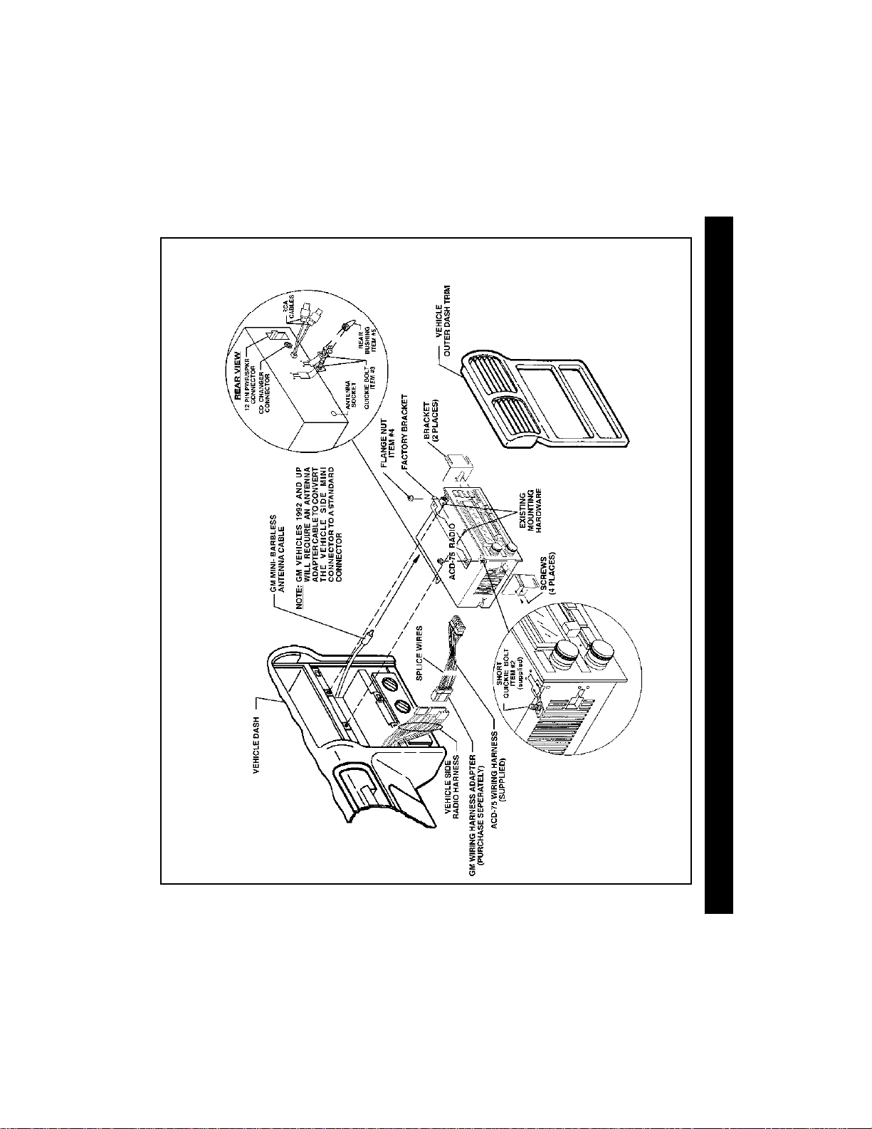
TYPICAL GM APPLICATION (See Figure 1.)
Radio Preparation
NOTE:For GM car installations, use the GM Hardware Kit, Part Number 150-1331, which is
furnished with the radio.
1. Match quickie bolt locations on the ACD-75 radio to the factory radio bolt locations, and
snap the short quickie bolts (Item #2) into the appropriate locations.
2. Attach the original factory brackets or those from the radio mounting kit (if required) to the
ACD-75 radio using the supplied flange nuts (Item #4) or use the enclosed bracket
(Item # 6) if the original factory brackets are not removable.
3. Some vehicle applications incorporate a rear mounting support. Match the rear quickie
INSTALLATION INSTRUCTIONS
bolt on the ACD-75 radio to the rear factory radio bolt location and snap the long quickie
bolt (Item #3) into place. Thread the plastic rear bushing (Item #5) fully onto the quickie
bolt.
4. Plug supplied wire harness (Item #1) into the mating socket on the rear of the ACD-75.
Installation
1. Connect the wiring harness from the radio to the vehicle side radio harness.
2. Plug the factory antenna cable into the antenna socket on the radio.
NOTE:GM vehicles 1992 and up will require an antenna adapter cable to convert the vehicle
mini connector to standard connector. Antenna adaptor cables are available at car
stereo speciality shops.
3. If a compatible CD changer is to be used with this radio, connect the DIN cable from the
changer to the mating socket on the radio. If an external amplifier will be used for the rear
speakers, connect the low-level output RCA leads from the radio to the low-level inputs on
the amplifier.
4. Reconnect the battery and perform a brief functional test of the radio to verify proper
performance.
5. After verification, turn off the ignition switch and fasten the radio to the sub-dash using the
mounting hardware previously removed from the factory radio.
6. Re-assemble the dash using the reverse of the disassembly procedure.
:
:
4
Page 5
WIRING DIAGRAM-TYPICAL INSTALLATION FOR GM
(Figure 1)
ITEM # 6
INSTALLATION INSTRUCTIONS
SPE
SPESPE
SPESPE
A
AA
AA
K
KK
KK
ER WIRING
ER WIRINGER WIRING
ER WIRINGER WIRING
# 1
ITEM
5
Page 6

TYPICAL CHRYSLER APPLICATION (See Figure 2.)
Radio Preparation:
NOTE: For Chrysler car installations, use the Chrysler Hardware Kit, Part Number 150-1332
1. Select two of the three mounting tabs provided (Items # 7, # 8 and # 9) and match the radio
mounting style of the vehicle as shown in Figures 3, 4 and 5.
NOTE: The tab number is stamped on the bottom of the tab.
DIO WIRINGDIO WIRING
DIO WIRINGDIO WIRING
DIO WIRING
AA
AA
A
2. Attach the mounting tabs to the radio chassis with the four 1/4” hex head screws provided.
RR
RR
R
3. Attach the 12-pin connector from the harness to the radio.
4. Plug the antenna cable into the antenna socket on the radio.
Installation:
1. Attach the ring lug on the ground wire (black) from the radio side harness along with the
INSTALLATION INSTRUCTIONS
vehicle side grounding strap to the rear of the radio chassis using the short quickie bolt
(Item #2) and the flange nut (Item # 4) provided.
2. Connect the mating side of the harness to the vehicle side wiring harness.
3. Connect the vehicle antenna cable to the radio antenna connector.
4. If a compatible CD changer is to be used with this radio, connect the DIN cable from the
changer to the mating socket on the radio. If an external amplifier will be used for the rear
speakers, connect the low-level output RCA leads from the radio to the low-level inputs on the
amplifier.
5. Re-connect the battery and perform a brief functional test of the radio to verify proper
performance.
6. After verification, turn off the ignition switch and install the radio into the sub-dash of the
vehicle using either the two 10mm hex-head screws (Item #10) provided, or the existing
factory hardware.
7. Re-assemble the dash using the reverse of the disassembly procedure.
6
Page 7

TYPICAL INSTALLATION FOR CHR YSLER
(Figure 2)
INSTALLATION INSTRUCTIONS
OR
(ITEM # 10)
10mm HEX-HEAD SCREWS
(2 PLACES)
ITEM #’S 7, 8, and 9
7
Page 8

POWER
COMPACT DISC PLAYER
EJECT
VOL
TUNE/SKIP
VOL
DIGITAL AUDIO
COMPACT
LOUD
T/F
EQ
MODE
BAND
MUTE
1
TOP SCN2RPT3RND
4
MONO LOC
ACD-75
CD+
6
CD-
5
100 WATT
TAB #1
T AB #2
Figure 3
8
INSTALLATION INSTRUCTIONS
TA B #2
ACD-75
POWER
BAND
MODE
MUTE
MONO LOC
ACD-75
POWER
BAND
MODE
MUTE
MONO LOC
TAB #2
100 WATT
LOUD
COMPACT
DIGITAL AUDIO
T/F
EQ
TOP SCN2RPT3RND
1
100 WATT
LOUD
COMPACT
DIGITAL AUDIO
T/F
EQ
TOP SCN2RPT3RND
1
4
Figure 4
4
Figure 5
COMPACT DISC PLAYER
EJECT
TAB #2
VOL
TUNE/SKIP
5
6
CD-
VOL
CD+
TAB #3
COMPACT DISC PLAYER
5
6
CD-
CD+
EJECT
VOL
TUNE/SKIP
VOL
Page 9

OPERATING INSTRUCT IONS
1 POWER ON-OFF BUTTON
Press this button to turn the unit on or off. The unit
will also turn on automatically when a compact
disc is inserted if the ignition switch is “on”.
2 VOLUME (LEVEL) CONTROL
To increase the volume level, press the VOL
button. The volume will increase and the level
will be shown on the display panel from a
minimum of
To decrease the volume level, press the VOL
button. The display will automatically return
H
to the normal indication 5 seconds after the last
volume adjustment or when another function is
activated. This control is also used in conjunction
with the Select (SEL) button to adjust the bass,
treble, balance and fader levels as described in
VOL 00 to a maximum of VOL 39.
4, 5, 6 and 7.
3 SELECT (SEL) CONTROL BUTTON
This button is used to select the audio function
(volume, bass, treble, balance, or fade) whose
setting is adjusted using the VOL
buttons. Pressing the SEL control button once
will set the unit for bass adjustment (BAS will
appear on the display panel) and an audible
beep will occur. Pressing the button additional
times will select treble adjustment (TRE on the
display), balance (BAL), or fader (FAD ), each
accompanied by a beep tone. The display will
automatically return to the normal indication 5
seconds after the last adjustment or when
another function is activated.
4 BASS CONTROL
To adjust the bass level, first select the Bass
mode by pressing the SEL button
indication appears on the display panel. Within
5 seconds of choosing the Bass mode, press
the VOL
response or the VOL
desired. The level will be shown on the display
panel from a minimum
BAS +12 (BAS 00 indicates flat response). The
display will automatically return to the normal
indication 5 seconds after the last adjustment or
when another function is activated.
5 TREBLE CONTROL
2
To adjust the treble level, first select the Treble
mode by pressing the SEL button
indication appears on the display panel. Within
2 button to decrease the bass
button to increase it as
BAS -12 to a maximum of
3 so the BAS
3 so the TRE
9
Page 10

5 seconds of choosing the Treble mode, press
the VOL
response or the VOL button to increase it as
desired. The level will be shown on the display
panel from a minimum
TRE +12 (TRE 00 indicates flat response). The
display will automatically return to the normal
indication 5 seconds after the last adjustment
or when another function is activated.
button 2 to decrease the treble
TRE -12 to a maximum of
6 LEFT/RIGHT BALANCE CONTROL
To adjust the left-right speaker balance, first
select the Balance mode by pressing the SEL
button
OPERATING INSTRUCTIONS
3 so the BAL indication appears on the
display panel. Within 5 seconds of choosing
the Balance mode, press the VOL
to adjust the stereo balance to the left channel
speakers or the VOL
right channel speakers. The balance position
will be shown on the display panel from
(full left) to BAL R16 (full right). When the volume
level between the left and right speakers is equal,
BAL 00 will be shown on the display panel. The
display will automatically return to the normal
indication 5 seconds after the last adjustment
or when another function is activated.
button to adjust it to the
7 FRONT/REAR FADER CONTROL
To adjust the front-rear speaker balance, first
select the Fader mode by pressing the Select
button
3 so the FAD indication appears on the
display panel. Within 5 seconds of choosing
the Fader mode, press the VOL
adjust the front-rear speaker balance to the rear
speakers or the VOL
front speakers. The fader position will be shown
on the display panel from
FAD F16 (full front). When the level between the
front and rear speakers is equal, FAD 00 will be
shown on the display panel. The display will
automatically return to the normal indication 5
seconds after the last adjustment or when
10
another function is activated.
button to adjust it to the
FAD R16 (full rear) to
button 2
BAL L16
button 2 to
8 LOUDNESS CONTOUR (LOUD)
When listening to music at low volume levels,
this feature will boost the bass and treble ranges
to compensate for the characteristics of human
hearing. Press the button momentarily to
activate this feature and the indication LOUD
will appear on the display panel. Pressing the
button again momentarily will deactivate the
feature (the LOUD indication will disappear from
the display panel).
9 AUDIO MUTE SELECTOR (MUTE )
Press this button momentarily to mute the
volume from the system (MUTE will appear
blinking on the display panel). Pressing the
button again, adjusting the VOL buttons
pressing the LOUD button, equalizer (EQ)
button, or select (SEL) button, will return to the
volume level setting in use before the Mute
function was activated.
2 , or
bl AM/FM BAND SELECTOR (RADIO BAND)
Each time this button is pressed, the radio band
is changed. The indication AM1, AM2, FM1,
FM2 or FM3 will appear on the display panel
according to your selection.
During integral CD player operation, pressing
this button will stop play of the disc and switch
to radio operation without ejecting the disc.
During this time, the DISC IN indication will
remain on t he display panel to show that a disc
is still loaded in the unit. Press the MODE
button to r et urn to disc play from the beginning
of the last track in play.
bm MANUAL UP/DOWN TUNING (+ / -)
AUTOMATIC SEEK TUNING (SEEK)
T o manually select a radio station, momentarily
press the (+
to advance the unit one digit higher or the
(
-) side of the button to tune one digit lower.
Pressing either side of the button for longer than
0.5 second will activate the Automatic Seek
Tuning function. The radio will seek the next
) side of the TUNE/SKIP button
Page 11

station in the selected direction and stop at that
frequency.
Press either side of the button again to resume
seek to the next station in the selected direction.
bn LOCAL/DISTANT SELECTOR (LOC)
This feature is used to select the strength of the
signals at which the radio will stop during
Automatic Seek Tuning. Pressing the button will
select the Local setting (LOC will appear on the
display panel) and only strong (local) stations
will be received. Pressing the button again will
select the Distant setting (LOC will disappear
from the display panel) and the radio will stop at
a wider range of signals, including weaker (more
distant) stations.
bo FM MONO/STEREO SELECTOR (MON)
During FM radio operation, this button is used
to select mono or stereo reception of the
broadcast signal. Under normal reception
conditions, the unit should be left in the stereo
mode as indicated by the ST
the display panel when tuned to an FM stereo
signal. If the stereo signal is too noisy for
comfortable listening, press the MON button to
switch to monaural reception (the ST
indication will disappear from the display panel).
To return to stereo reception mode, press the
button again so that the ST
appears in the display panel.
indication on
indication
bp PRE-SET SCAN (PS)
AUTO-STORE TUNING (AS)
Press this button momentarily to scan the stations
pre-set into the six memories of each of the
AM bands or each of the FM bands. On each
selected band, the unit will stop at each pre-set
station for 5 seconds before continuing to the
next pre-set station (the pre-set number on the
display panel will flash during Pre-Set Scan
operation). Press the button again momentarily
to stop Pre-Set Scan operation and remain on
the selected frequency. If no buttons are
pressed during the scan, the unit will return to
the original station before the scan.
When the button is pressed and held for longer
than 2 seconds, the unit will beep and activate
the Auto-Store Tuning feature. The radio will
automatically scan and enter up to 6 stations
into the pre-set memories on the band in use.
If you have already set the pre-set memories to
your favorite stations, activating the Auto-Store
Tuning feature will erase those stations and
enter the new ones. This feature is most useful
when travelling in a new area where you are
not familiar with the local stations.
bq STATION PRE-SET MEMORIES
To set any of the 6 pre-set memories in each
band, use the following procedure:
1. Turn the radio on and select the desired
band.
2. Select the first station to be pre-set using the
Manual TUNE/SKIP Controls
3. Press the pre-set button to be set and continue
to hold it in for approximately 2 seconds. The
pre-set number will appear on the display
panel and two beeps will sound, indicating
that the station is now set into that pre-set
memory position. The station can now be
recalled at any time by pressing that button.
4. Repeat the above procedure for the remaining
5 pre-sets on that band and for the other 4
bands on the unit.
bm.
br LIQUID CRYSTAL DISPLA Y PANEL
The Liquid Crystal Display (LCD) panel displays
the frequency, time, and activated functions.
NOTE:It is a characteristic of LCD panels that,
if subjected to cold temperatures for an
extended period of time, they may take
longer to illuminate than under normal
conditions. In addition, the visibility of
the numbers on the LCD may slightly
decrease. The LCD read-out will return
to normal when the temperature
increases to a normal range.
OPERATING INSTRUCTIONS
11
Page 12

bs FUNCTION DISPLAY (LEVEL METER)
The Function Display consits of five bar graphs
which provide a visual representation of the
volume level and the channel signal levels. The
volume level is represented by three thin bar
graphs. As the volume is increased, the number
of illuminated segments will increase. The
channel signal levels are represented by the
wider bar graphs. As the strength of the signal
applied to either the left or right channel
increases, the number of illuminated segments
will increase.
bt MODE SELECTOR (MODE)
OPERATING INSTRUCTIONS
This button is used to select the radio, or the
CD player/CD changer (if installed) playback
mode. Each press of the button will select a
different mode as indicated on the display panel.
During CD player operation, this button may be
used to change to radio or CD changer mode
without ejecting the disc. The DISC IN
indication will remain on the display panel to
show that a disc is still loaded in the unit. When
the CD changer is operating, the disc symbol
(
) will appear on the display panel. Press
the button again to return to radio or CD player
mode (DISC play resumes from the point at
which it was stopped).
bu DISC SLOT
Gently insert the disc into the slot (label surface
facing up) until the soft-loading mechanism
engages and pulls the disc in. The LOAD
indication will momentarily appear on the display
panel followed by the total playing time of the
disc. The (
becomes animated, and the PLAY indication
momentarily appears followed by the track
number and elapsed time.
CAUTION:This unit is designed for play of
12
) symbol illuminates and
ONLY. Do not attempt to use 3"
(8cm) CD-Singles in this unit, either
with or without an adapter, as
damage to the player and/or disc can
occur. Such damage will not be
covered by the Warranty on this
product.
cl TRACK SELECT (+ / - )
The Track Select functions are used to quickly
access the beginning of a particular track. Each
time the Forward Track Select (+
TUNE/SKIP button is pressed, the next higher
track number will be selected as shown on the
display panel. Similarly, each time the Backward
Track Select (
the next lower track number will be selected as
shown on the display panel.
- ) side of the button is pressed,
) side of the
cm CUE/REVIEW FUNCTIONS (+ / -)
High-speed audible search to any section of the
disc can be made by the Cue and Review
functions. Press and hold the Cue (+
of the TUNE/SKIP button to advance rapidly in
the forward direction. (The advancing disc playing
time will be shown on the display panel) or the
Review (
rapidly in the backward direction (The decreasing
disc playing time will be shown on the display
panel). During either function, the elapsed time
within each track will automatically be shown on
the display panel.
-) side of the button to advance
) side
cn TRACK ONE POSITION (TOP)
When the Track One Position (TOP) button is
pressed during disc play, play is q uic kly returned
to the begining of the CD, Track 1.
co TRACK SCAN SELECTOR (SCN)
During disc play , press this button to play the first
10 seconds of each track on the disc (SCN will
appear on the display panel). When a desired
track is reached, press the SCN button again to
cancel the function (SCN will disappear from the
display panel) and play of the selected track will
continue. Scan mode will also be canceled by
activating the Repeat Play
MODE bt, T OP cn, or Track Select cl functions.
cp, Random Play cq,
Page 13

cp REPEAT PLAY SELECT OR (RPT)
During disc play , press this button to repeat the
play of the selected track (RPT will appear on
the display panel). Play of the track will continue
to repeat until the button is pressed again and
the RPT indication disappears from the display
panel. Repeat Play mode will also be canceled
by activating the Scan
TOP cn functions.
co, Random Play cq, or
cq RANDOM PLAY SELECTOR (RND)
During disc play, press this button to play the
tracks on the disc in a random shuffled order
(RND will appear on the display panel). In
Random Play mode, the Track Select function
cl will also select tracks in the random order
instead of the normal progression. The Random
play mode can be canceled by pressing the
button again (RND indication will disappear from
the display panel) or by activationg the Repeat
Play
cp, Scan co, or TOP cn functions.
cr DISC SELECT UP/DOWN (CD+/CD-)
During CD changer operation, these buttons are
used to select the desired disc for play. Refer
to the section describing CD Changer Controls.
cs DISC EJECT ( )
Disc play is stopped and the disc is ejected
when the EJECT (
appears on the display). Radio or CD changer
operation will automatically resume. If the disc
is not removed from the unit within 15 seconds
of being ejected, it will automatically be re-loaded
into the unit to prevent it from being accidentally
damaged (DISC IN will appear on the display
panel to indicate that a disc is loaded in the
player). Play of the disc can be resumed by
using the MODE button
player function.
) button is pressed (EJECT
bt to choose the CD
ct TIME/FREQUENCY SELECTOR (T/F)
During radio operation, press this button to call
the time display on the incorporated quartz clock.
The display will return to the radio frequency or
disc play elapsed time indication after 5 seconds
if the time is not being re-set.
cu EQUALIZER BUTTON (EQ)
The EQ button applies preset sound effects to
the unit’s audio output signal. The EQ
button,when pressed, will activate one of four
operating modes (no equalization, ROCK,
CLAS, or POP). When the EQ function is active,
the bass and treble levels cannot be changed.
When the EQ function is not active, the unit
returns to the user set bass and treble levels.
dl THEFT-DETERRENT LED
Located on the chassis behind the front panel,
a light-emitting diode (LED) will flash when the
panel is removed. The flashing light serves as
a visual warning to the would-be thief that the
unit has been disabled by removal of the front
panel.
dm RESET BUTTON
A RESET button is also accessible when the
front panel is removed, and can be used to
activate the reset circuitry. However , this feature
should only be used under the following
circumstances as it will erase the time and
pre-set memories:
1. Upon initial installation after all wiring is
completed.
2.If there is a malfunction of any of the switches,
on the unit, pressing the RESET button may
clear the system and permit a return to normal
operation.
OPERATING INSTRUCTIONS
13
Page 14

dn FRONT PANEL RELEASE BUTTON
(RELEASE )
This button is used to release the mechanism
that holds the front panel to the chassis. To
detach the front panel, press the button so that
the panel releases on the right side. Then
carefully swing the right side out until the left
edge disengages. To re-attach the panel,
engage the left side first and then gently press
in the right side until the it clicks into place.
NOTES ON USE OF FRONT PANEL
1. Make sure the front panel is right-side-up
when attaching it to the chassis as it cannot
be attached when up-side down.
OPERATING INSTRAUCTIONS / SET TING THE CLOCK
2.Do not press very hard on the front panel
when attaching it to the chassis. No more
than light to moderate pressure should be
needed.
3.When attaching the front panel, insert the
left side first, making sure it is properly
engaged in the chassis frame. Then
carefully press the right side into place until
the panel clicks into position.
4.When taking the front panel with you, please
use the supplied carrying case to protect the
panel from dirt and damage. Make sure
there is no dust or dirt on the electrical
terminals on the back of the panel as this
could cause intermittent operation or other
malfunctions.
SETSET
TT
ING THE CLOCKING THE CLOCK
SET
T
ING THE CLOCK
SETSET
TT
ING THE CLOCKING THE CLOCK
1. Switch the vehicle ignition and radio “on”.
2. Press the Time/Frequency button to call the time display.
3. Press and hold the Time/Frequency Selector button ct, and then press the Down Tuning
( -) button to adjust the hours and AM/PM indication or the Up Tuning (+ ) button to
adjust the minutes to the correct time.
4. Five seconds after the button is released, following the last hour or minute adjustment, the
14
time will be set in the unit and the display will return to the normal indication.
Page 15

CD PLCD PL
CD PL
CD PLCD PL
If a problem should develop while operating the CD player, an error code (ER-1, ER-2, ER-3,
etc.) may appear on the display panel. This can indicate a number of problems with the unit,
including a mechanical error or an error in the microprocessor control of the player. If an error
code should appear, try ejecting and re-loading the disc into the player. While the disc is out of
the unit, make sure it is clean, undamaged, and loaded correctly (label surface up). You may
also try activating the RESET button
memories.
If the suggested measures do not solve the problem, contact an approved warranty station near
you for further assistance.
Size: 7.875" W x 3.125" H x 6.5" D
Operating Voltage: 12 volts DC, negative ground
Fuse Ratings: Constant (Yellow wire): 15 AMP.
Output Power: 160 watts maximum
Output Wiring: Floating-ground type designed for 4 speaker use.
Output Impedance: Compatible with 4 – 8 ohm speakers.
Low-Level Output: 500 mv.
Tuning Range: AM: 530 – 1,710 kHz. (10 kHz. step)
Sensitivity: AM: 20 uv.
FM Stereo Separation: >20 dB
CD Frequency Response: 17 – 20 kHz. +0/-3 dB
CD Signal/Noise Ratio: >65 dB
CD Channel Separation: >65 dB
CD Distortion: 0.2%
*Specifications are subject to change without notice.
AA
YER ERRYER ERR
A
YER ERR
AA
YER ERRYER ERR
OR CODESOR CODES
OR CODES
OR CODESOR CODES
dm on the unit, but this will also erase the time and pre-set
*SPECIFICATIONS*SPECIFICATIONS
*SPECIFICATIONS
*SPECIFICATIONS*SPECIFICATIONS
200.025 mm x 79.375 mm x 165.1 mm
Switched (Red wire): 0.5 AMP.
(40 watts x 4 channels)
Front and rear channels CANNOT be combined
(bridged) for use with 2 speakers.
RCA low-level outputs (rear channels).
FM: 87.5 – 107.9 MHz. (200 kHz. step)
FM: 1.5 uv.
ERROR CODE / SPECIFICATIONS
15
Page 16

CD CHCD CH
CD CH
CD CHCD CH
Built into this radio are controls to operate an
optional CD changer. Please check with your
Rampage/Audiovox car stereo specialist or call
1-800-645-4994 for recommendations of the
models that will work with this radio.
Adjustment of the audio functions (volume,
tone, balance, and fader) for the CD changer
operate in the same manner as they do for
radio play. The following controls will operate
the CD changer when it is installed and
connected to this radio. Refer to the owner’s
CD CHANGER CONTROLS
manual included with the CD changer for
instructions on the installation and correct
loading and use of the CD magazine.
do CD CHANGER MODE SELECTOR
(MODE)
During radio or CD player operation, press this
button to select operation of the CD changer
as shown by CdC on the display panel. Disc
play will begin and the disc and track number
will be shown on the display panel, as well as
the Cd-c indication. If a new magazine has
been loaded into the changer, play will begin
from the first track of the first disc in the magazine.
If a magazine was already in the changer, play
will resume from the track on the disc previously in play.
dp & dq DISC SELECT (CD+ & CD-)
During CD changer operation, these buttons
are used to select the desired disc for play.
To advance to a higher number disc, press
the CD+ button
disc, press the CD- button
the disc on play will be shown on the display
panel.
dp. T o return to a lower number
dq. The number of
dr TRACK SELECT (+ / -)
During disc play , the T rack Select functions are
used to quickly access the beginning of a
16
particular track. Each time the Forward Track
Select (+
) side of the button is pressed,
AA
NGER CONTRNGER CONTR
A
NGER CONTR
AA
NGER CONTRNGER CONTR
the next higher track number will be selected
as shown on the display panel. Similarly, each
time the Backward Track Select (
the button is pressed, the next lower track
number will be selected as shown on the
display panel.
ds CUE/REVIEW FUNCTIONS (+ / -)
During disc play, high-speed audible search
to any section of the disc can be made by the
Cue and Review functions. Press and hold
the Cue (+
rapidly in the forward direction (the disc play
symbol will rotate forward on the display panel)
or the Review (
advance rapidly in the backward direction (the
disc symbol will rotate backwards on the
display panel).
dt TRACK/DISC SCAN SELECTOR (SCN)
During disc play, when the SCN button is
pressed, the SCN indication will appear on the
display panel, and the first 10 seconds of each
track on the disc will be played in order. When
a desired track is reached, press the SCN
button twice and play of the selected track will
continue (SCN will disappear from the display
panel). The Track Scan mode will also be
canceled by activating the Repeat, Random
Play , TOP, or MODE functions.
When the SCN button is pressed twice, the
DISC and SCN indications will appear on the
display panel and the first 10 seconds of the
first track on each disc in the magazine will be
played. When a desired disc is reached, press
the SCN button again and play of the selected
disc will continue (
pear from the display panel). The Disc Scan
mode will also be canceled by activating the
Repeat Play, Random Play, TOP, or MODE
functions.
du DISC/TRACK REPEA T PLA Y (RPT)
During disc play, when the RPT button is
OLOL
SS
OL
S
OLOL
SS
) side of the button to advance
-) side of the button to
DISC and SCN will disap-
-) side of
Page 17

pressed, the RPT indication will appear on the
display panel and play of the selected track
will be continually repeated until the Rrack
Repeat mode is canceled by pressing the RPT
button twice or by activating the Scan
Random Play
When the RPT button is pressed twice, the DISC
and RPT indications will appear on the display
panel and play of the selected disc will by
continually repeated until the Disc Repeat mode
is canceled by pressing the RPT button again
or by activating the Scan, Random Play or TOP
functions.
el functions.
dt or
el DISC/TRACK RANDOM PLA Y (RND)
During disc play, when the RND button is
pressed, the RND indication will appear on the
display panel and the tracks on the disc will be
played in a random, shuffled order. The Track
Select button dr will also select tracks in the
shuffled order instead of the normal progression.
The Random Track mode can be canceled by
pressing the RND button twice or by activating
the Scan dt or Repeat Play eu functions.
When the RND button is pressed twice, the DISC
and RND indications will appear on the display
panel and the discs in the magazine will by
played in a random, shuffled order, as well as
the tracks on each disc. After playing a track
selected at random from a disc in the magazine,
the unit will select another disc at random and
play a randomly selected track on it. This will
continue until the Random Disc mode is
canceled by pressing the RND button again
or by activating the Scan dt, Repeat Play du
or TOP functions.
CD CHANGER CONTROLS / CD CHANGER ERROR CODES
CD CHCD CH
CD CH
CD CHCD CH
If a problem should develop while operating the CD changer, the following error codes may
appear on the display panel.
ER-1: Indicates that there is no magazine loaded in the CD changer.
ER-2: Indicates a problem with the magazine eject function.
ER-3: Indicates an error in the disc loading function.
ER-4: Indicates an error in the disc un-loading function.
ER-5: Indicates an error in the magazine position.
ER-6: Indicates an error in the laser pick-up position.
ER-7: Indicates an error in the laser focus on the disc.
In any of the above situations, try ejecting the CD magazine from the changer and make sure
the discs are clean, undamaged, and loaded correctly (refer to the Owner’s Manual of the CD
changer). Re-load the magazine and check for proper operation. You may also try activating
the RESET button
If the suggested measures do not solve the problem, contact an approved warranty station near
you for further assistance.
dm on the unit, but this will also erase the time and pre-set memories.
AA
NGER ERRNGER ERR
A
NGER ERR
AA
NGER ERRNGER ERR
OR CODESOR CODES
OR CODES
OR CODESOR CODES
17
1414
14
1414
Page 18

CD CH
CD CHCD CH
CD CHCD CH
A
AA
AA
NGER CONTR
NGER CONTRNGER CONTR
NGER CONTRNGER CONTR
OL
OLOL
OLOL
S
SS
SS
CARE AND MAINTENANCECARE AND MAINTENANCE
CARE AND MAINTENANCE
CARE AND MAINTENANCECARE AND MAINTENANCE
The radio section of your new sound system does not require any maintenance. We recommend
that you keep this manual for reference on the many features found in this unit as well as how to
set the clock.
The compact disc player section also requires no routine maintenance, but proper understanding
of its use and handling will help you obtain maximum enjoyment of its capabilities. The following
points should be observed:
l When cleaning the interior of the vehicle, do not get water or cleaning fluids on the unit.
l The CD player is a precision instrument and will not operate properly in extreme heat or cold.
In case of such conditions, wait until the interior temperature of the vehicle reaches a normal
temperature before using the player.
l If the temperature inside the player gets too hot, a protective circuit will automatically stop
play of the disc. In this case, allow the unit to cool off before operating the player again.
CARE AND MAINTENANCE
l Never insert anything other than a 5" (12 cm) compact disc into the player as the mechanism
can be damaged by foreign objects.
l Do not attempt to use 3" (8 cm) CD-Single discs in this unit, either with or without an adaptor,
as damage to the player and/or disc may occur. Such damage will not be covered by the
Warranty on this product.
l When not using the disc player, always remove the compact disc. Do not leave an ejected
disc sitting in the disc slot as this can expose it to sunlight and other causes of damage.
l Do not attempt to open the unit chassis. There are no user serviceable parts or adjustments inside.
l When the vehicle warms up during cold weather or under damp conditions, moisture may
condense on the lens of the disc player. Should this occur, the player will not operate properly
until the moisture has evaporated.
l The unit is designed with a vibration dampening CD mechanism to minimize interruption of
disc play due to normal vibration in a moving vehicle. When driving on very rough roads,
however, occasional sound skips may occur. This will not scratch or damage the disc and
normal play will resume when the rough conditions cease.
HANDLING COMPACT DISCS
Dirt, dust, scratches, and warpage can cause skips in the playback and deterioration of sound
quality. Please follow these guidelines to take care of your compact discs:
l Use only compact discs with the mark .
l Fingerprints, dust, and dirt should be carefully wiped off the disc’s playing surface (shiny side)
with a soft cloth. Wipe in a straight motion from the inside to the outside of the disc.
l Never use chemicals such as record sprays, household cleaners or thinner to clean compact
discs. Such chemicals can irreparably damage the disc’s surface.
l Discs should be kept in their storage cases when not in use.
l Do not expose discs to direct sunlight, high temperatures or high humidity for extended periods.
l Do not stick paper, tape, or labels on the disc surfaces nor write on them with any type of marker.
18
Page 19

12 MONTH LIMITED WARRANTY
AUDIOVOX CORPORATION (the Company) warrants to the original retail purchaser of
this product that should this product or any part thereof, under normal use and
conditions, be proven defective in material or workmanship within 12 months from the
date of original purchase, such defect(s) will be repaired or replaced with new or
reconditioned product (at the Company's option) without charge for parts and repair
labor.
To obtain repair or replacement within the terms of this Warranty, the product is to be
delivered with proof of warranty coverage (e.g. dated bill of sale), specification of
defect(s), transportation prepaid, to the warranty center at the address shown below.
This Warranty does not extend to the elimination of car static or motor noise, to correction
of antenna problems, to costs incurred for installation, removal, or reinstallation of the
product, or damage to tapes, compact discs, speakers, accessories, or vehicle electrical
systems.
This Warranty does not apply to any product or part thereof which, in the opinion of the
Company, has suffered or been damaged through alteration, improper installation,
mishandling, misuse, neglect, accident, or by removal or defacement of the factory serial
number/bar code label(s). THE EXTENT OF THE COMPANY'S LIABILITY UNDER
THIS WARRANTY IS LIMITED TO THE REPAIR OR REPLACEMENT PROVIDED
ABOVE AND, IN NO EVENT, SHALL THE COMPANY'S LIABILITY EXCEED THE
PURCHASE PRICE PAID BY PURCHASER FOR THE PRODUCT.
This Warranty is in lieu of all other express warranties or liabilities. ANY IMPLIED
WARRANTIES, INCLUDING ANY IMPLIED WARRANTY OF MERCHANTABILITY,
SHALL BE LIMITED TO THE DURATION OF THIS WRITTEN WARRANTY. ANY
ACTION FOR BREACH OF ANY WARRANTY HEREUNDER INCLUDING ANY
IMPLIED WARRANTY OF MERCHANTABILITY MUST BE BROUGHT WITHIN A
PERIOD OF 30 MONTHS FROM DATE OF ORIGINAL PURCHASE. IN NO CASE
SHALL THE COMPANY BE LIABLE FOR ANY CONSEQUENTIAL OR INCIDENTAL
DAMAGES FOR BREACH OF THIS OR ANY OTHER WARRANTY, EXPRESS OR
IMPLIED, WHATSOEVER. No person or representative is authorized to assume for the
Company any liability other than expressed herein in connection with the sale of this
product.
Some states do not allow limitations on how long an implied warranty lasts or the
exclusion or limitation of incidental or consequential damage so the above limitations or
exclusions may not apply to you. This Warranty gives you specific legal rights and you
may also have other rights which vary from state to state.
U.S.A. : AUDIOVOX CORPORATION, 150 MARCUS BLVD., HAUPPAUGE, NY 11788 l 1-800-645-4994
CANADA: CALL 1-800-645-4994 FOR LOCATION OF WARRANTY STATION SERVING YOUR AREA
128-4270E
WARR A NT Y
19
Page 20

© 2000 Audiovox Electronics Corp., Hauppauge, NY 11788 128-5812A
 Loading...