

Page 1
OWNER'S MANUAL
MANUEL D'UTILISATION
MANUAL DEL USUARIO
ACD-16
VOL
SEL
VOL
BAND
TRACK
EJ
PWR
MUTE
REL
G
N
I
N
U
T
AUX IN
CD- CD+ T/F
RND
ACD-16ACD-16
ACD-16
ACD-16ACD-16
INT
MONLOU LOC/RPT
DETACHABLE FRONT PANEL, AM/FM/MPX RADIO WITH COMPACT DISC
PLAYER, CD CHANGER CONTROLS
AND QUARTZ CLOCK
AUTORADIO AM/FM/MPX AVEC FAÇADE AMOVIBLE, DOTÉ D'UN LECTEUR
DE DISQUES COMPACTS, DE COMMANDES DE CHANGEUR DE CD ET D'UNE
MONTRE À QUARTZ
PANEL DELANTERO DESMONTABLE CON
RADIO AM/FM/MPX, CON REPRODUCTOR Y CAMBIADOR
DE DISCOS COMPACTOS Y RELOJ DE CUARZO
128-5807B
Released 5-10-00.
Rev. A: 6-7-00 – Add French and Spanish.
Rev. B: 5-7-02 Added CD-R and CD-RW specification notice.
1 of 44
Page 2
INSTALLATION INSTRUCTIONSINSTALLATION INSTRUCTIONS
INSTALLATION INSTRUCTIONS
INSTALLATION INSTRUCTIONSINSTALLATION INSTRUCTIONS
This unit is designed for installation in cars, trucks, and vans with an existing radio opening. In many cases, a
IONSIONS
IONSIONS
IONS
special installation kit will be required to mount the radio to the dashboard. These kits are available at electronics
TT
TT
T
supply stores and car stereo specialist shops. Always check the kit application before purchasing to make sure the
kit works with your vehicle. If you need a kit but cannot find it available, call our toll-free “HELP” line at 1-800-645-4994.
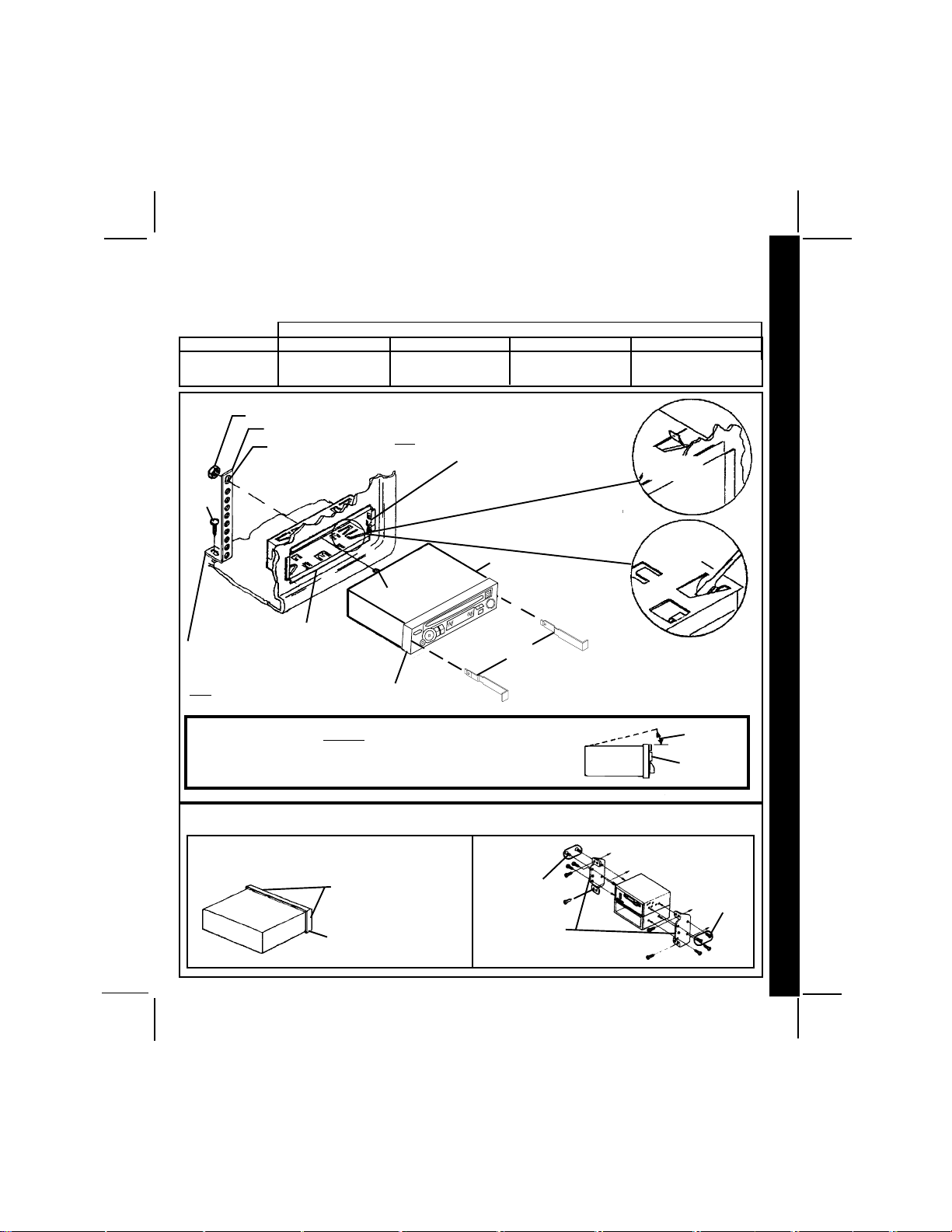
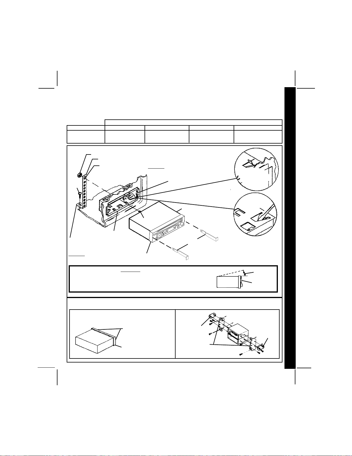
UNIVERSAL INSTALLATION PROCEDURE USING MOUNTING SLEEVE
1. Slide the mounting sleeve off of the chassis. If it is locked into position, use the removal tools (supplied)
to disengage it.
2. Check the dashboard opening size by sliding the mounting sleeve into it. If the opening is not large enough, carefully
cut or file as necessary until the sleeve easily slides into the opening. Do not force the sleeve into the opening
or cause it to bend or bow. Check that there will be sufficient space behind the dashboard for the radio chassis.
ION INSTRUCION INSTRUC
ION INSTRUCION INSTRUC
ION INSTRUC
3. Locate the series of bend tabs along the top, bottom, and sides of the mounting sleeve. With the sleeve
TT
TT
T
fully inserted into the dashboard opening, bend as many of the tabs outward as necessary so that the
AA
AA
A
sleeve is firmly secured to the dashboard.
4. Place the radio in front of the dashboard opening so that the wiring can be brought through the mounting
ALLALL
ALLALL
ALL
sleeve. Follow the wiring diagram carefully and make certain all connections of the wiring harness are
secure and insulated with wire nuts or electrical tape to insure proper operation of the unit. After completing
the wiring connections, turn the unit on to confirm operation (ignition switch must be “on”). If unit does not
INSTINST
INSTINST
INST
operate, re-check all wiring until problem is corrected.
NOTE: Adjust AM antenna trimmer NOW. Refer to label on right side of chassis for adjustment instructions.
Once proper operation is achieved, turn off the ignition switch and proceed with final mounting of the chassis.
5. Carefully slide the radio into the mounting sleeve making sure it is right-side-up until it is fully seated and
the spring clips lock it into place.
6. Attach one end of the perforated support strap (supplied) to the screw stud on the rear of the chassis using
the hex nut provided. Fasten the other end of the perforated strap to a secure part of the dashboard either
above or below the radio using the screw provided. Bend the strap to position it as necessary.
CAUTION: The rear of the radio must be supported with the strap to prevent damage to the dashboard
7. Test radio operation by referring to the Operating Instructions.
INSTALLATION USING KITS
1. If your vehicle requires the use of an installation kit to mount this radio, follow the instructions included with
the installation kit to attach the radio to the mounting plate supplied with the kit.
2. Wire and test the radio as described in Step 4 above.
3. Install the radio/mounting plate assembly to the sub-dashboard according to the instructions of the installation kit.
4. Attach the support strap to the radio and dashboard as described in Step 6 above.
5. Replace the dashboard trim panel.
ISO INSTALLATION PROCEDURE
This unit has threaded holes in the chassis side panels which may be used with the original factory mounting
brackets of some Toyota, Nissan, Mitsubishi, Isuzu, Hyundai and Honda vehicles to mount the radio to the
dashboard. Please consult with your local car stereo specialist shop for assistance on this type of installation.
1. Remove the existing factory radio from its dashboard or center console mounting. Save all hardware and
brackets as they will be used to mount the new radio.
2. Carefully un-snap the plastic frame from the front of the new radio chassis. Remove and discard the frame.
3. Remove the factory mounting brackets and hardware from the existing radio and attach them to the new radio.
CAUTION: DO NOT EXCEED M5 X 6 MM MAXIMUM SCREW SIZE.
4. Wire the new radio to the vehicle as per step 4 above.
11
1
11
5. Mount the new radio assembly to the dashboard or center console using the reverse procedure of step 1.
from the weight of the radio or improper operation due to vibration.
LONGER SCREWS MAY TOUCH AND DAMAGE COMPONENTS INSIDE THE CHASSIS.
128-5807B
2 of 44
Page 3
TT
OLL-FREE INSTOLL-FREE INST
T
OLL-FREE INST
TT
OLL-FREE INSTOLL-FREE INST
The installation and wiring connections for this unit are so simple, we doubt you'll need our help, but, if you
do, we're here to help you. Just call our toll-free telephone assistance line at 1-800-645-4994 during the days
and hours shown (U.S.A. and Canada only).
DAY
MON. - FRI.
SATURDAY
NUT (5MM)
SCREW
(5MM)
FASTEN THIS END TO SECURE
PART OF DASHBOARD.
DRILL HOLE IF NECESSARY.
NOTE: PLASTIC FRAME MUST BE REMOVED (UN-SNAP ON LEFT
AND RIGHT SIDES) TO USE REMOVAL TOOLS.
PACIFIC
5:30AM - 4PM
6AM - 2PM
UNIVERSAL INSTALLATION USING MOUNTING SLEEVEUNIVERSAL INSTALLATION USING MOUNTING SLEEVE
UNIVERSAL INSTALLATION USING MOUNTING SLEEVE
UNIVERSAL INSTALLATION USING MOUNTING SLEEVEUNIVERSAL INSTALLATION USING MOUNTING SLEEVE
PERFORATED STRAP
FASTEN THIS END TO SCREW
STUD ON REAR OF CHASSIS
SCREW STUD
MOUNTING SLEEVE
ALLALL
AA
TT
ALL
ALLALL
MOUNTAIN
6:30AM - 5PM
7AM - 3PM
EXISTING DASH OPENING
FILE EDGES TO FIT IF NECESSARY - DO NOT OVERFILE
NOTE: IF DASH IS SOLID, USE REAR SIDE (WITHOUT THE LIP) OF
MOUNTING SLEEVE AS A TEMPLATE & CUT OPENING
ION ASSISTION ASSIST
A
T
ION ASSIST
AA
TT
ION ASSISTION ASSIST
7:30AM - 6PM
8AM - 4PM
RADIO
REMOVAL TOOLS
CENTRAL
AA
A
AA
NCENCE
NCE
NCENCE
EASTERN
8:30AM - 7PM
9AM - 5PM
BEND TOP
TABS UPWARD
BEND BOTTOM
TABS DOWNWARD
INST
INSTINST
INSTINST
ALL
ALLALL
ALLALL
A
AA
AA
T
TT
TT
ION INSTRUC
ION INSTRUCION INSTRUC
ION INSTRUCION INSTRUC
T
TT
TT
IONS
IONSIONS
IONSIONS
FOR PROPER OPERATION OF THE CD PLAYER, THE CHASSIS MUST BE
MOUNTED WITHIN 20° OF HORIZONTAL. MAKE SURE THE UNIT IS
MOUNTED WITHIN THIS LIMITATION.
REMOVE THE PLASTIC FRAME FROM THE FRONT OF THE
CHASSIS BY CAREFULLY UN-SNAPPING IT.
CAUTION:
UN-SNAP ON LEFT AND
RIGHT SIDES
PLASTIC FRAME
ISO INSTALLATIONISO INSTALLATION
ISO INSTALLATION
ISO INSTALLATIONISO INSTALLATION
SIDE VIEW
OF
CHASSIS
MAXIMUM
SCREW SIZE
M5 x 6
FACTORY MOUNTING
BRACKETS
20° MAX.
FRONT PANEL
TYPICAL INSTALLATION
MAXIMUM
SCREW SIZE
M5 x 6
128-5807B
3 of 44
22
2
22
Page 4

RR
AA
DIO WIRINGDIO WIRING
R
A
DIO WIRING
RR
AA
DIO WIRINGDIO WIRING
REFER TO PAGE 4 FOR SPEAKER WIRING
ANTENNA
RADIO WIRING
AUTOMATIC
ANTENNA
EXISTING
ANTENNA
CABLE
BLUE (0.5 AMP FUSE)
IMPORTANT
THE BLUE WIRE CAN BE USED
TO REMOTELY ACTIVATE AN
AUTOMATIC ANTENNA OR AN
EXTERNAL AMPLIFIER (SEE
ANTENNA OR AMPLIFIER
MANUAL)
RED (0.5 AMP FUSE)
SCREW
BLACK
YELLOW (5 AMP FUSE)
IMPORTANT
THIS WIRE MUST BE CONNECTED
AS SHOWN OR RADIO WILL NOT
OPERATE PROPERLY
SEE PAGE 4 FOR
SPEAKER WIRING
METAL PART OF DASH
(DRILL HOLE IF
NECESSARY)
CAR
FUSEBLOCK
"RADIO" OR
"ACCESSORY" FUSE
CAR BATTERY
POSITIVE (+) TERMINAL
12 VOLT BATTERY
ANTENNA SOCKET
ON REAR OF RADIO
33
3
33
RADIO
128-5807B
4 of 44
Page 5
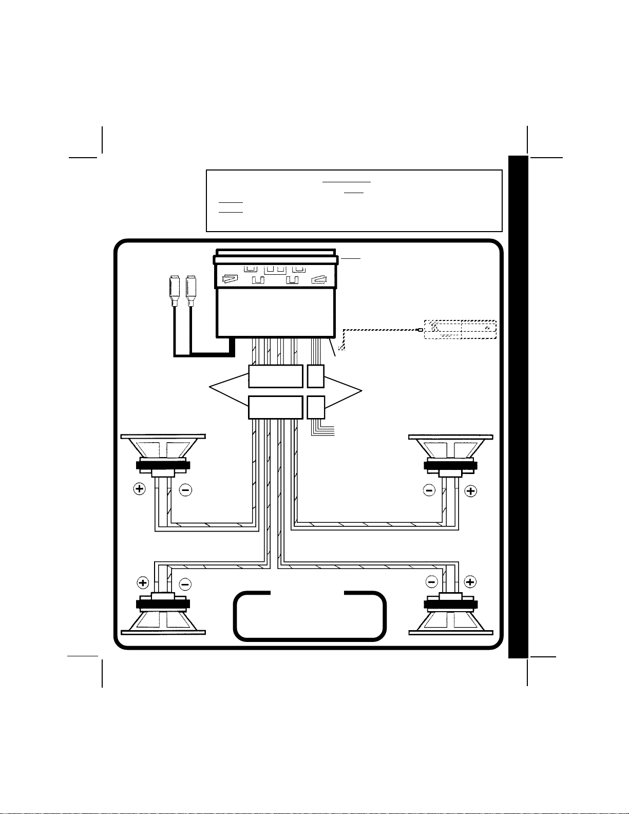
SPEAKER WIRINGSPEAKER WIRING
SPEAKER WIRING
SPEAKER WIRINGSPEAKER WIRING
REFER TO PAGE 3
FOR RADIO WIRING
RCA JACKS
LINE OUT
FOR USE WITH
OPTIONAL
EXTERNAL
AMPLIFIERS
RED=RIGHT REAR
WHITE=LEFT REAR
9-PIN PLUGS
WARNING!
l THE AMPLIFIERS IN THIS RADIO ARE ONLY DESIGNED FOR USE WITH 4 SPEAKERS.
NEVER COMBINE (BRIDGE) OUTPUTS FOR USE WITH 2 SPEAKERS.
l
l
NEVER GROUND NEGATIVE SPEAKER LEADS TO CHASSIS GROUND.
l FAILURE TO WIRE EXACTLY AS SHOWN BELOW MAY CAUSE ELECTRICAL
NOTE:
CHECK WITH YOUR RAMPAGE/AUDIOVOX CAR
STEREO SPECIALIST OR CALL 1-800-645-4994 FOR
RECOMMENDATIONS OF THE MODELS THAT WILL
WORK WITH YOUR RADIO.
RADIO
DIN CABLE
(SUPPLIED WITH
CD CHANGER).
8-PIN DIN SOCKET FOR CONNECTION TO
OPTIONAL CD CHANGER
4-PIN PLUGS
OPTIONAL
CD CHANGER
6
COMPACT
SPE
SPESPE
SPESPE
A
AA
AA
K
KK
KK
ER WIRING
ER WIRINGER WIRING
ER WIRINGER WIRING
LEFT FRONT SPEAKER
WHITE w/BLACK STRIPE
WHITE
GREEN
GREEN w/BLACK STRIPE
SEE PAGE 3 FOR
RADIO WIRING
GRAY w/BLACK STRIPE
GRAY
VIOLET
VIOLET w/BLACK STRIPE
RIGHT FRONT SPEAKER
HELP!
1-800-645-49941-800-645-4994
1-800-645-4994
1-800-645-49941-800-645-4994
Monday - Friday
Saturday
LEFT REAR SPEAKER RIGHT REAR SPEAKER
8:30am - 7:00pm Eastern
9:00am - 5:00pm Eastern
128-5807B
5 of 44
44
4
44
Page 6
OPEROPER
OPER
OPEROPER
IONSIONS
IONSIONS
IONS
TT
TT
T
ING INSTRUCING INSTRUC
ING INSTRUCING INSTRUC
ING INSTRUC
TT
TT
T
AA
AA
A
OPEROPER
OPEROPER
OPER
AA
TT
ING INSTRUCING INSTRUC
A
T
ING INSTRUC
AA
TT
ING INSTRUCING INSTRUC
VOL
S
EL
2
3
4
5
6
7
26
10
VOL
AUX IN
TT
IONSIONS
T
IONS
TT
IONSIONS
16
13
ACD-16
19
17
BAND
12
CD- CD+ T/F
9
15
RND
24
8
20
INT
MONLOU LOC/RPT
23
22
25
14
EJ
MUTE
N
I
N
U
T
TRACK
21
1
11
15
PWR
REL
G
18
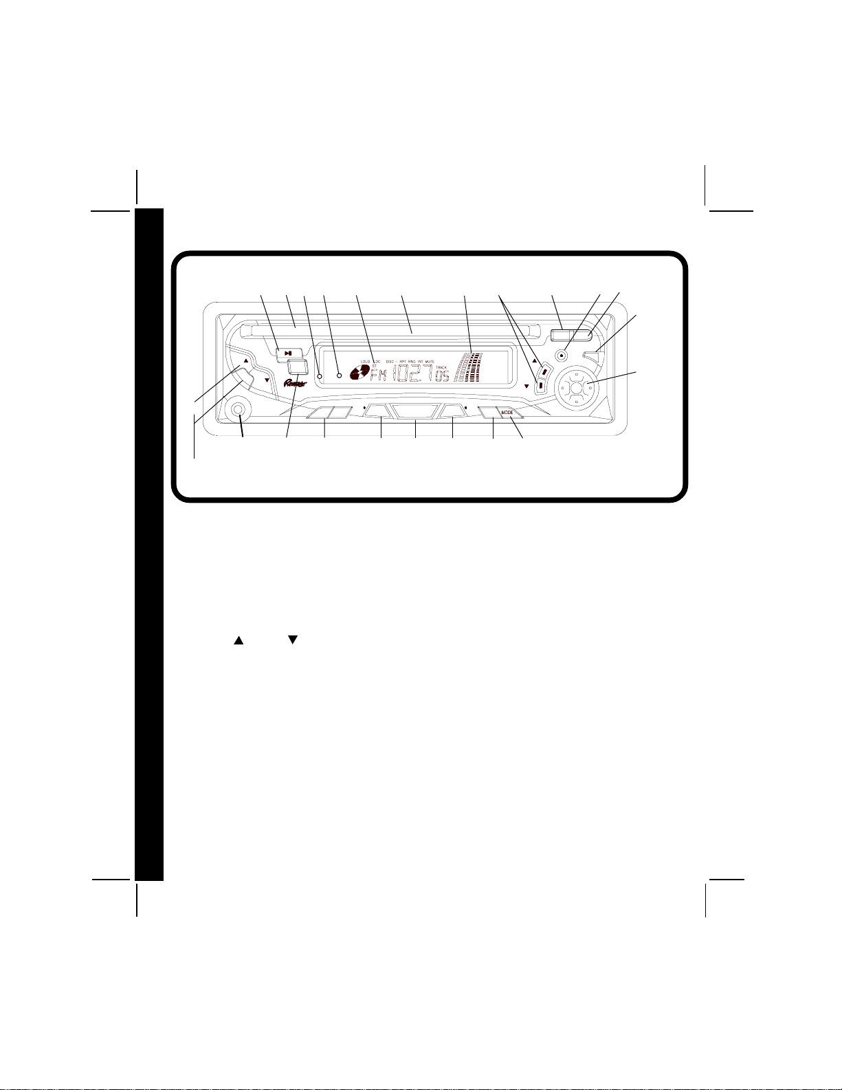
1 ON-OFF POWER BUTTON (PWR)
Press this button to turn the unit on or off. The
unit will also turn on automatically when a
compact disc is inserted if the ignition switch
is “on”.
2 VOLUME/LEVEL CONTROL
(VOL / VOL )
To increase the volume level, press the
volume up side of the control. The volume
will increase and the level will be shown on
the display panel from a minimum of
VOL 0 to a maximum of VOL 63. To
decrease the volume level, press the
volume down side of the control. The
display will automatically return to the normal
indication 5 seconds after the last volume
adjustment or when another function is
activated. This control is also used in
conjunction with the Select button 3 to
55
5
55
adjust the bass, treble, balance and fader
levels as described in 4, 5, 6 and 7.
3 SELECT BUTTON (SEL)
This button is used to select the audio
function (volume, bass, treble, balance, or
fade) to be adjusted using the Level
control 2. Pressing the Select button
once will set the unit for volume adjustment.
It is recommended that the volume level
control 2 be used. Pressing the Select
button twice will set the unit for bass
adjustment (BAS will appear on the display
panel). Pressing the button additional times
will select treble adjustment (TRE on the
display), balance (BAL), or fader (FAd).
The display will automatically return to the
normal indication 5 seconds after the last
adjustment or when another function is
activated.
4 BASS CONTROL
To adjust the bass level, first select the
128-5807B
6 of 44
Page 7
Bass mode by pressing the Select button
3 so the BAS indication appears on the
display panel. Within 5 seconds of choosing
the Bass mode, press the down side of the
Level control 2 to decrease the bass
response or press the up side to increase
it as desired. The level will be shown on the
display panel from a minimum BAS -7 to a
maximum of BAS 7 (BAS 0 indicates flat
response). The display will automatically
return to the normal indication 5 seconds
after the last adjustment or when another
function is activated.
5 TREBLE CONTROL
To adjust the treble level, first select the
Treble mode by pressing the Select button
3 so the TRE indication appears on the
display panel. Within 5 seconds of choosing
the Treble mode, press the down side of
the Level control 2 to decrease the treble
response or press the up side to increase
it as desired. The level will be shown on the
display panel from a minimum TRE -7 to a
maximum of TRE 7 (TRE 0 indicates flat
response). The display will automatically
return to the normal indication 5 seconds
after the last adjustment or when another
function is activated.
6 LEFT/RIGHT BALANCE CONTROL
To adjust the left-right speaker balance,
first select the Balance mode by pressing
the Select button 3 so the BAL indication
appears on the display panel. Within 5
seconds of choosing the Balance mode,
press the down side of the Level control 2
to adjust the stereo balance to the left
channel speakers or press the up side to
adjust it to the right channel speakers. The
balance position will be shown on the display
panel from BAL 10 (full left) to BAr 10 (full
right). When the volume level between the
left and right speakers is equal, BAL 0 will
be shown on the display panel. The display
will automatically return to the normal
indication 5 seconds after the last
adjustment or when another function is
activated.
7 FRONT/REAR FADER CONTROL
To adjust the front-rear speaker balance,
first select the Fader mode by pressing the
Select button 3 so the FAd indication
appears on the display panel. Within 5
seconds of choosing the Fader mode, press
the down side of the Level control 2 to
adjust the front-rear speaker balance to the
rear speakers or press the up side to adjust
it to the front speakers. The fader position
will be shown on the display panel from FAr
10 (full rear) to FAF10 (full front). When the
level between the front and rear speakers
is equal, FAd 0 will be shown on the display
panel. The display will automatically return
to the normal indication 5 seconds after the
last adjustment or when another function is
activated.
8 TRACK SELECT (TRACK /
TRACK )
The Track Select functions are used to
quickly access the beginning of a particular
track during CD player and CD changer
operation. Each time the Forward Track
Select (TRACK ) side of the button is
pressed, the next higher track number will
be selected as shown on the display panel.
Similarly, each time the Backward Track
Select (TRACK ) side of the button is
OPER
OPEROPER
OPEROPER
A
AA
AA
T
TT
TT
ING INSTRUC
ING INSTRUCING INSTRUC
ING INSTRUCING INSTRUC
T
TT
TT
IONS
IONSIONS
IONSIONS
66
6
66
128-5807B
7 of 44
Page 8
pressed, the next lower track number will
be selected as shown on the display panel.
IONSIONS
IONSIONS
IONS
TT
TT
T
9 DISC SELECT ( CD- CD+)
During CD changer operation, this button
is used to select the desired disc play. To
advance to a higher number disc, press the
CD+ button. To decrement to a lower
number disc, press the CD- button. The
ING INSTRUCING INSTRUC
ING INSTRUCING INSTRUC
ING INSTRUC
number of the disc in play will be shown on
TT
TT
T
the display panel.
AA
AA
A
bl CD PLAY/PAUSE SELECTOR ( )
OPEROPER
OPEROPER
OPER
During CD player and CD changer
operation, pressing this button will
temporarily stop play of the disc (the
indication will flash on the display panel).
Press the button again to resume play of
the disc from the point at which it was
stopped.
bm AUDIO MUTE SELECTOR (MUTE)
Press this button to mute the volume from
the unit (MUTE will appear on the display
panel). Pressing the button again or
adjusting the Volume control 2 will return
to the volume level setting in use before the
Mute function was activated.
bn LIQUID CRYSTAL DISPLAY PANEL
The Liquid Crystal Display (LCD) panel
displays the frequency and activated
functions.
NOTE: It is a characteristic of LCD panels
that, if subjected to cold temperatures
for an extended period of time,
they may take longer to illuminate
than under normal conditions. In
77
7
77
addition, the visibility of the numbers
on the LCD may slightly decrease.
The LCD read-out will return to
normal when the temperature
increases to a normal range.
bo DISC SLOT
With the label surface facing up, fully
insert a compact disc into the slot until
the soft-loading mechanism engages and
pulls the disc in. The LOAdCd indication
will momentarily appear on the display panel
followed by CdP and the playing time of the
disc. Disc play will then begin with the track
number and rotating disc play symbol ( )
on the display panel.
NOTE:This unit is designed for play of
standard 5" (12cm) Compact Discs
ONLY. Do not attempt to use 3"
(8cm) CD-Singles in this unit, either
with or without an adapter, as
damage to the player and/or disc
can occur. Such damage will not be
covered by the Warranty on this
product.
bp DISC EJECT (EJ)
Disc play is stopped and the disc is ejected
by pressing this button (EJCd will appear on
the display panel). Remove the disc and
insert another disc into the unit to begin play
of the new disc or press the Function Mode
Selector cm to choose radio or CD changer
mode operation. Discs will be ejected
when the button is pressed and the ignition
switch is on.
Radio or CD changer operation will
automatically resume depending on which
mode was in operation prior to disc play. If
the disc is not removed from the unit within
10 seconds of being ejected, it will
automatically be re-loaded into the unit to
128-5807B
8 of 44
Page 9

prevent it from being accidentally damaged
( will appear on the display panel to
indicate that a disc is loaded in the player).
Play of the disc can be resumed by using
the Function Mode Selector
CD player function.
NOTE: To prevent an ejected disc from
accidentally being damaged, always
remove the disc from the unit. Do
not leave the disc extending from
the disc slot.
cm to choose
bq FRONT PANEL RELEASE BUTTON
(REL)
This button is used to release the mechanism
that holds the front panel to the chassis. To
detach the front panel, press the button so
that the panel releases form the chassis.
Grasp the panel at the middle and pull it off
of the chassis.
To re-attach the panel, press the left side of
the panel in place first (left facing radio) and
then press the right side of the panel until
the mechanism locks it into place.
NOTES ON USE OF FRONT PANEL
1. Make sure the front panel is rightside-up when attaching it to the chassis
as it cannot be attached when up-side
down.
2. Do not press very hard on the front
panel when attaching it to the chassis.
No more than light to moderate pressure
should be needed.
3. When attaching the front panel, make
sure it is centered in the chassis frame
and is pressed straight into position.
4. When taking the front panel with you,
please use the supplied carrying case to
protect the panel from dirt and damage.
Make sure there is no dust or dirt on
the electrical terminals on the back of
the panel as this could cause
intermittent operation or other
malfunctions.
br THEFT-DETERRENT L.E.D.
Located on the chassis behind the front
panel, a light-emitting diode (LED) will flash
when the panel is removed. The flashing
light serves as a visual warning to the
would-be thief that the unit has been disabled
by removal of the front panel.
bs RE-SET BUTTON
A Re-Set button is located on the front of the
chassis (front panel must be removed to
access the button). The re-set circuitry is
provided to protect the microprocessor
circuitry and should only be activated under
the following circumstances as it will erase
the time and pre-set memories.
1. Upon initial installation after all wiring
is completed.
2. If there is a malfunction of any of the
switches on the unit, pressing the Re-Set
button may clear the system and return to
normal operation.
bt MANUAL TUNING CONTROL
Turn this knob clockwise to tune upward in
frequency on the band in use, counterclockwise to tune downward in frequency.
The frequency to which you are tuned will be
shown in digital form on the display panel.
When tuning in a station, always adjust
OPER
OPEROPER
OPEROPER
A
AA
AA
T
TT
TT
ING INSTRUC
ING INSTRUCING INSTRUC
ING INSTRUCING INSTRUC
T
TT
TT
IONS
IONSIONS
IONSIONS
88
8
88
128-5807B
9 of 44
Page 10

the control so that the correct broadcast
frequency is shown on the display and
adjust the control so that you are receiving
a clear signal. If the radio is tuned offfrequency, you could experience distorted
audio, noise and other reception problems.
clock. The display will return to the radio
frequency indication after 5 seconds.
During CD player and CD changer operation,
the first press of the button will call the time
display. In either case, the display will
return to the disc indication after 5 seconds.
bu AM/FM BAND SELECTOR (BAND)
Each time this button is pressed, the radio
band is changed. The indication AM or FM
will appear on the display panel according
to your selection.
OPERATING INSTRUCTIONS
cl LEVEL METER
This display consists of two bar segments
which indicate the level of the audio signal.
The number of segments present in each
bar corresponds to the audio signal level
(more segments equals a st ronger signal).
During CD Player and CD Changer
operation, the display provides an indication
of the audio signal level present on the CD.
cm FUNCTION SELECTOR (MODE)
This button is used to select the playback
mode (radio, CD Player or optional CD
Changer). With each press of the button, a
different playback mode will be selected as
indicated on the front panel display.
Radio (FM or AM on display) [ CD Disc
Player (CdP on display) [ CD Changer
(CdC on display).
During CD Player operation, the button
may be used to change to radio or CD
changer without ejecting the disc.
cn TIME/FREQUENCY SELECTOR (T/F)
During operation, press this button to call
the time display on the incorporated quartz
99
9
99
co LOCAL/REPEAT CONTROL (LOC/RPT)
During radio operation, pressing this button
selects the local setting for the reception of
strong signals. The LOC indication will
appear on the display panel. Pressing the
button again will deactivate the function.
During CD Player and CD Changer operation,
pressing the button will continously repeat
the current disc track. The RPT indication
will appear in the display panel. Pressing
the button again wil deactivate this function.
cp LOUD/RANDOM CONTROL
(LOU/RND)
During radio or CD operation when listening
to music at low volume levels this feature
will boost bass and treble ranges to
compensate for the characteristics of
human hearing. Press the button
momentarily to activate this feature and the
indication LOUD will appear on the display
panel. Pressing the button again
momentarily will deactivate the feature (the
LOUD indication will disappear from the
display panel). During CD Player and CD
Changer operation, pressing and holding
this button for several seconds will cause
the CdP and CD Changer to play disc
tracks in random order. The indication
RND will appear on the display panel.
Pressing and holding the button again for
several seconds will deactivate this function.
128-5807B
10 of 44
Page 11
cq MONO RADIO PLAY/INTRODUCTION
DISC PLAY (MON/INT)
During FM radio operation, this button is
used to select mono or stereo reception of
the broadcast signal. Under normal
reception conditions, the unit should be left
in the stereo mode as indicated by the
ST indication on the display panel when
tuned to an FM stereo signal. If the stereo
signal is too noisy for comfortable listening,
press the FM Mono/Stereo Selector button
to switch to mono reception (the ST
indication will disappear from the display
panel). To return to stereo reception mode,
press the button again so that the ST
indication appears in the display panel.
During CD player or optional CD changer
disc play, press this button to play the first
10 seconds of each track on the disc (INT
will appear on the display panel). When a
desired track is reached, press the button
again to cancel the function (INT will
disappear from the display panel) and play
of the selected track will continue. IntroScan mode will also be canceled by
activating the Repeat Play co function.
cr AUX IN CONNECTOR
The AUX IN connector provides the user
option of applying an external source to the
radio. The connector is compatable with
most portable CD and cassette players or
an MP3 digital audio playback unit. When
the external source is connected, only that
media is played by the radio; no other input
sources (radio or CD) are operative.
OPER
OPEROPER
OPEROPER
A
AA
AA
T
TT
TT
ING INSTRUC
ING INSTRUCING INSTRUC
ING INSTRUCING INSTRUC
T
TT
TT
IONS
IONSIONS
IONSIONS
128-5807B
11 of 44
1010
10
1010
Page 12
SETSET
TT
ING THE CLOCKING THE CLOCK
SET
T
ING THE CLOCK
SETSET
TT
ING THE CLOCKING THE CLOCK
1. Switch the vehicle ignition and radio “on”.
2. Press the Time/Frequency button to call the time display.
OR CODEOR CODE
OR CODEOR CODE
OR CODE
3. Press and hold in the Time/Frequency Selector button cn with the time displayed. The
time display will blink.
4. Press the VOL button to adjust the hours and AM/PM indication and VOL button
to adjust the minutes to the correct time.
5. Five seconds after the last hour or minute adjustment is made, the time will be set in
the unit and the display will return to the normal indication.
CD PLCD PL
CD PL
CD PLCD PL
ING THE CLOCK / ERRING THE CLOCK / ERR
ING THE CLOCK / ERRING THE CLOCK / ERR
ING THE CLOCK / ERR
ER-1: Indicates excessive temperature conditions at the CD changer. The error code
TT
TT
T
SETSET
SETSET
SET
ER-2: Indicates the disc is not loading or ejecting properly. Try re-loading or pressing
ER-3: Not user serviceable, contact an approved warranty station near you for
ER-4: Not user serviceable, contact an approved warranty station near you for
ER-5: Not user serviceable, contact an approved warranty station near you for
ER-6: Not user serviceable, contact an approved warranty station near you for
ER-7: Not user serviceable, contact an approved warranty station near you for
ER-8: Not user serviceable, contact an approved warranty station near you for
ER-9: Eject the disc, make sure it is clean, undamaged and loaded correctly (label
ER-10: Not user serviceable, contact an approved warranty station near you for
ER-11: Indicates that there is no magazine loaded in the CD Changer.
1111
11
1111
will go off and play will resume when the temperature at the changer returns to a
normal range.
the Ej ec t b utt on . C he ck the co nd it io n of th e disc in use or try another disc.
further assistance.
further assistance.
further assistance..
further assistance..
further assistance.
further assistance.
side up).
further assistance.
AA
YER ERRYER ERR
A
YER ERR
AA
YER ERRYER ERR
OR CODESOR CODES
OR CODES
OR CODESOR CODES
128-5807B
12 of 44
Page 13

SPECIFICATIONSSPECIFICATIONS
SPECIFICATIONS
SPECIFICATIONSSPECIFICATIONS
Size: 7" W x 2" H x 6-1/8" D
178 mm x 50 mm x 155 mm
Operating Voltage: 12 volts DC, negative ground
Fuse Ratings: Constant (yellow) lead: 5 AMP.
Switched (red) lead: 0.5 AMP.
Output Power: 60 watts maximum
(15 watts x 4 channels)
Output Wiring: Floating-ground type designed for 4 speaker use.
Output Impedance: Compatible with 4-8 ohm speakers.
Tuning Range: AM: 530 – 1,720 KHz.
FM: 87.5 – 107.9 MHz.
Sensitivity: AM: 20 uv.
FM: 1.5 uv.
FM Stereo Separation: >25 dB
CD Frequency Response: 20 – 20,000 Hz. ±1 dB
CD Signal/Noise Ratio: >60 dB
SPECIFICATIONS
CD Channel Separation: >60 dB
CD Distortion: 0.2%
*Specifications are subject to change without notice.
CD-R AND CD-RW PLAYBACK CAPABILITY
This model can play most CD-R and CD-RW media that contains audio programs.
Playback of both CD-R and CD-RW depends on the conditions of the recording equipment
and the CD-R or CD-RW disc quality. In some cases, a CD-R or CD-RW disc cannot be
played on this unit.
128-5807B
13 of 44
1212
12
1212
Page 14
CARE AND MAINTENANCECARE AND MAINTENANCE
CARE AND MAINTENANCE
CARE AND MAINTENANCECARE AND MAINTENANCE
NCENCE
NCENCE
NCE
The radio section of your new sound system does not require any maintenance. We
recommend that you keep this manual for reference on the many features found in this unit as
well as how to set the clock.
The compact disc player section also requires no routine maintenance, but proper
INTENAINTENA
INTENAINTENA
INTENA
understanding of its use and handling will help you obtain maximum enjoyment of its
capabilities. The following points should be observed:
l When cleaning the interior of the vehicle, do not get water or cleaning fluids on the unit.
l The CD player is a precision instrument and will not operate properly in extreme heat or cold.
ND MAND MA
ND MAND MA
ND MA
In case of such conditions, wait until the interior temperature of the vehicle reaches a normal
temperature before using the player.
RE ARE A
RE ARE A
RE A
l If the temperature inside the player gets too hot, a protective circuit will automatically stop
play of the disc. In this case, allow the unit to cool off before operating the player again.
CACA
CACA
CA
l Never insert anything other than a 5" (12 cm) compact disc into the player as the mechanism
can be damaged by foreign objects.
l Do not attempt to use 3" (8 cm) CD-Single discs in this unit, either with or without an adaptor,
as damage to the player and/or disc may occur. Such damage will not be covered by the
Warranty on this product.
l When not using the disc player, always remove the compact disc. Do not leave an ejected
disc sitting in the disc slot as this can expose it to sunlight and other causes of damage.
l Do not attempt to open the unit chassis. There are no user serviceable parts or adjustments inside.
l When the vehicle warms up during cold weather or under damp conditions, moisture may
condense on the lens of the disc player. Should this occur, the player will not operate
properly until the moisture has evaporated.
l The unit is designed with a vibration dampening CD mechanism to minimize interruption of
disc play due to normal vibration in a moving vehicle. When driving on very rough roads,
however, occasional sound skips may occur. This will not scratch or damage the disc and
normal play will resume when the rough conditions cease.
HANDLING COMPACT DISCS
Dirt, dust, scratches, and warpage can cause skips in the playback and deterioration of sound
quality. Please follow these guidelines to take care of your compact discs:
l Use only compact discs with the mark .
l Fingerprints, dust, and dirt should be carefully wiped off the disc’s playing surface (shiny side)
with a soft cloth. Wipe in a straight motion from the inside to the outside of the disc.
l Never use chemicals such as record sprays, household cleaners or thinner to clean compact
discs. Such chemicals can irreparably damage the disc’s surface.
l Discs should be kept in their storage cases when not in use.
l Do not expose discs to direct sunlight, high temperatures or high humidity for extended periods.
1313
13
1313
l Do not stick paper, tape, or labels on the disc surfaces nor write on them with any type of marker.
128-5807B
14 of 44
Page 15
12 MONTH LIMI12 MONTH LIMI
12 MONTH LIMI
12 MONTH LIMI12 MONTH LIMI
AUDIOVOX CORPORATION (the Company) warrants to the original retail purchaser of
this product that should this product or any part thereof, under normal use and
conditions, be proven defective in material or workmanship within 12 months from the
date of original purchase, such defect(s) will be repaired or replaced with new or
reconditioned product (at the Company's option) without charge for parts and repair
labor.
To obtain repair or replacement within the terms of this Warranty, the product is to be
delivered with proof of warranty coverage (e.g. dated bill of sale), specification of defect(s),
transportation prepaid, to the warranty center at the address shown below.
This Warranty does not extend to the elimination of car static or motor noise, to correction
of antenna problems, to costs incurred for installation, removal, or reinstallation of the
product, or damage to tapes, compact discs, speakers, accessories, or vehicle electrical
systems.
This Warranty does not apply to any product or part thereof which, in the opinion of the
Company, has suffered or been damaged through alteration, improper installation,
mishandling, misuse, neglect, accident, or by removal or defacement of the factory serial
number/bar code label(s). THE EXTENT OF THE COMPANY'S LIABILITY UNDER
THIS WARRANTY IS LIMITED TO THE REPAIR OR REPLACEMENT PROVIDED
ABOVE AND, IN NO EVENT, SHALL THE COMPANY'S LIABILITY EXCEED THE
PURCHASE PRICE PAID BY PURCHASER FOR THE PRODUCT.
This Warranty is in lieu of all other express warranties or liabilities. ANY IMPLIED
WARRANTIES, INCLUDING ANY IMPLIED WARRANTY OF MERCHANTABILITY,
SHALL BE LIMITED TO THE DURATION OF THIS WRITTEN WARRANTY. ANY
ACTION FOR BREACH OF ANY WARRANTY HEREUNDER INCLUDING ANY IMPLIED
WARRANTY OF MERCHANTABILITY MUST BE BROUGHT WITHIN A PERIOD OF 30
MONTHS FROM DATE OF ORIGINAL PURCHASE. IN NO CASE SHALL THE
COMPANY BE LIABLE FOR ANY CONSEQUENTIAL OR INCIDENTAL DAMAGES
FOR BREACH OF THIS OR ANY OTHER WARRANTY, EXPRESS OR IMPLIED,
WHATSOEVER. No person or representative is authorized to assume for the Company
any liability other than expressed herein in connection with the sale of this product.
Some states do not allow limitations on how long an implied warranty lasts or the
exclusion or limitation of incidental or consequential damage so the above limitations or
exclusions may not apply to you. This Warranty gives you specific legal rights and you
may also have other rights which vary from state to state.
U.S.A.: AUDIOVOX CORPORATION, 150 MARCUS BLVD., HAUPPAUGE, NEW YORK 11788 • 1-800-645-4994
CANADA: CALL 1-800-645-4994 FOR LOCATION OF WARRANTY STATION SERVING YOUR AREA
TED WTED W
TED W
TED WTED W
AA
A
AA
RRRR
RR
RRRR
AA
NTNT
YY
A
NT
Y
AA
NTNT
YY
Form No. 128-4270E
W
WW
WW
A
AA
AA
RR
RRRR
RRRR
A
AA
AA
NT
NTNT
NTNT
Y
YY
YY
128-5807B
15 of 44
1414
14
1414
Page 16

NOTICE D'INSTALLATIONNOTICE D'INSTALLATION
NOTICE D'INSTALLATION
Cet appareil est conçu pour être installé dans les voitures, camions et fourgonnettes dotés d'un logement aménagé dans le
IONION
IONION
ION
tableau de bord. Le recours à une trousse d'installation sera souvent nécessaire pour poser l'autoradio sur le tableau de bord.
TT
TT
T
On peut se procurer ces trousses dans les magasins d'électronique et chez les spécialistes de l'autoradio. Vérifiez toujours
AA
AA
A
l'usage de la trousse avant l'achat de façon à être sûr que celle-ci est compatible avec votre véhicule. Si vous avez besoin
d'une trousse mais ne pouvez vous la procurer, appelez notre service de dépannage sans frais au 1-800-645-4994.
ALLALL
ALLALL
ALL
MÉTHODE DE POSE UNIVERSELLE À L'AIDE DE LA DOUILLE DE MONTAGE
1. Dégagez la douille de montage du châssis. Si celle-ci est verrouillée, utilisez les outils de dépose (fournis) pour l'extraire.
2. Vérifiez la taille du logement sur le tableau de bord en y introduisant la douille de montage. Si l'ouverture est trop juste,
découpez-la ou limez-la avec précaution pour l'agrandir jusqu'à ce que la douille de montage puisse facilement coulisser
dans le logement. Ne forcez pas sur la douille pour la faire rentrer dans l'ouverture, elle pourrait se tordre ou se gauchir.
Vérifiez que le dégagement derrière le tableau de bord est suffisant pour accueillir le châssis de l'autoradio.
3. Localisez la série de lames à plier situées sur le haut, le bas et les parties latérales de la douille de montage. Après avoir
complètement introduit la douille dans le logement du tableau de bord, pliez autant de lames qu'il le faudra vers l'extérieur
ICE D'INSTICE D'INST
ICE D'INSTICE D'INST
ICE D'INST
pour fixer solidement la douille au tableau de bord.
TT
TT
T
4. Placez l'autoradio en face de l'ouverture du tableau de bord de façon à pouvoir faire passer les fils à travers la douille
de montage. Suivez attentivement le schéma de câblage et assurez-vous que toutes les connexions du faisceau de fils
NONO
NONO
NO
sont solides et qu'elles sont isolées à l'aide d'écrous fils ou de chatterton de façon à assurer le bon fonctionnement de
l'appareil. Après avoir effectué le câblage, allumez l'appareil pour en vérifier le fonctionnement (vous devez mettre le
contact). Si l'appareil ne fonctionne pas, revérifiez les branchements jusqu'à ce que le problème soit résolu.
REMARQUE : Réglez le condensateur ajustable d'appoint de l'antenne AM MAINTENANT. Reportez-vous aux consignes
d'installation figurant sur l'étiquette située sur le côté droit du châssis de l'autoradio. Une fois que l'appareil fonctionne,
coupez le contact et procédez à la pose définitive du châssis.
5. Introduisez avec précaution l'autoradio dans la douille de montage, en vous assurant que vous l'avez bien mis à l'endroit,
jusqu'à ce qu'il soit complètement encastré et que les agrafes à ressort se ferment.
6. Fixez une extrémité de la patte de support perforée (fournie) au goujon prisonnier à l'aide de l'écrou hexagonal fourni.
Fixez l'autre extrémité de la patte perforée à un endroit solide du tableau de bord situé soit au-dessus, soit au-dessous
de l'autoradio à l'aide de la vis et de l'écrou hexagonal fournis. Pliez la patte selon l'angle voulu.
ATTENTION : L'arrière de l'autoradio doit impérativement être soutenu par la patte afin de prévenir tout dommage que
7. Testez le fonctionnement de l'autoradio en vous reportant à la Notice d'utilisation de l'appareil.
INSTALLATION AU MOYEN DE LA TROUSSE
1. Si votre véhicule nécessite une trousse d'installation pour poser cet autoradio, suivez les instructions de la trousse pour
fixer l'autoradio sur la douille de montage fournie.
2. Branchez et testez l'autoradio comme décrit à l'étape 4.
3. Installez l'ensemble autoradio/plaque de montage sur la partie inférieure du tableau de bord en suivant les instructions
de la trousse d'installation.
4. Fixez la patte de support à l'autoradio et au tableau de bord comme décrit à l'étape 6 ci-dessus.
5. Remettez le panneau d'habillage sur le tableau de bord.
MÉTHODE DE POSE ISO
Les panneaux latéraux du châssis de cet appareil sont dotés de trous filetés pouvant être utilisés avec les supports de montage
d'origine de certains véhicules Toyota, Nissan, Mitsubishi, Isuzu, Hyundai et Honda pour monter l'autoradio sur le tableau de
bord. Veuillez consulter votre magasin d'autoradios local pour toute assistance concernant ce type de pose.
1. Enlevez l'autoradio d'origine du tableau de bord ou de sa console centrale. Conservez tout le matériel et les fixations car
vous en aurez besoin pour monter le nouvel autoradio.
2. Désencliquetez avec précaution le cadre en plastique situé sur le devant du châssis du nouvel autoradio. Retirez et jetez
le cadre.
3. Retirez les supports de montage et le matériel de l'autoradio d'origine et fixez-les sur le nouvel autoradio.
ATTENTION : NE PAS UTILISER DE VIS D'UNE TAILLE SUPÉRIEURE À M5 X 8 MM.
4. Branchez le nouvel autoradio sur le véhicule en suivant l'étape 4 ci-dessus.
1515
15
1515
5. Montez le nouveau bloc autoradio sur le tableau de bord ou sur la console centrale en suivant l'étape 1 en sens inverse.
pourrait occasionner le poids de l'autoradio au tableau de bord ainsi que tout mauvais fonctionnement
dû aux vibrations.
DES VIS D'UNE LONGUEUR SUPÉRIEURE POURRAIENT TOUCHER ET ENDOMMAGER LES
ÉLÉMENTS SE TROUVANT À L'INTÉRIEUR DU CHÂSSIS.
NOTICE D'INSTALLATIONNOTICE D'INSTALLATION
128-5807B
16 of 44
Page 17
ASSISTANCE SANS FRAIS POUR L'INSTALLATIONASSISTANCE SANS FRAIS POUR L'INSTALLATION
ASSISTANCE SANS FRAIS POUR L'INSTALLATION
L'installation et les branchements de l'appareil sont très simples et vous n'aurez en principe pas besoin d'aide, dans le cas
contraire cependant, nous sommes là pour vous aider. Il vous suffit d'appeler notre service dépannage sans frais au
1-800-645-4994 aux horaires et jours indiqués (États-Unis et Canada uniquement).
ASSISTANCE SANS FRAIS POUR L'INSTALLATIONASSISTANCE SANS FRAIS POUR L'INSTALLATION
NO
NONO
NONO
T
TT
TT
ICE D'INST
ICE D'INSTICE D'INST
ICE D'INSTICE D'INST
JOUR
DU LUN. AU VEND.
LE SAMEDI
ÉCROU (5 MM)
VIS
(5 MM)
FIXEZ CETTE EXTRÉMITÉ À UN ENDROIT
SOLIDE DU TABLEAU DE BORD. PERCEZ
UN TROU LE CAS ÉCHÉANT.
REMARQUE: LE CADRE EN PLASTIQUE DOIT ÊTRE RETIRÉ
(DÉSENCLIQUETEZ LES PARTIES GAUCHES ET DROITES)
POUR POUVOIR UTILISER LES OUTILS DE DÉPOSE.
POUR QUE LE LECTEUR DE CD FONCTIONNE CORRECTEMENT,
L'ANGLE D'INSTALLATION DU CHÂSSIS NE DOIT PAS DÉPASSER 20°
PAR RAPPORT À L'HORIZONTALE. ASSUREZ-VOUS QUE L'INSTALLATION DE L'APPAREIL RÉPOND À CES SPÉCIFICATIONS.
PACIFIQUE
DE 5 H 30 À 16 H
DE 6 H À 14 H
POSE UNIVERSELLE À L'AIDE DE LA DOUILLE DE MONTAGEPOSE UNIVERSELLE À L'AIDE DE LA DOUILLE DE MONTAGE
POSE UNIVERSELLE À L'AIDE DE LA DOUILLE DE MONTAGE
POSE UNIVERSELLE À L'AIDE DE LA DOUILLE DE MONTAGEPOSE UNIVERSELLE À L'AIDE DE LA DOUILLE DE MONTAGE
PATTE PERFORÉE
FIXEZ CETTE EXTRÉMITÉ AU
GOUJON PRISONNIER À
L'ARRIÈRE DU CHÂSSIS
GOUJON PRISONNIER
DOUILLE DE MONTAGE
ATTENTION :
ROCHEUSES
DE 6 H 30 À 17 H
DE 7 H À 15 H
LOGEMENT EXISTANT DU TABLEAU DE BORD
LIMEZ LES BORDS POUR ADAPTER L'OUVERTURE - NE LIMEZ
PAS TROP
REMARQUE : S'IL N'Y A PAS D'OUVERTURE DANS LE TABLEAU DE BORD, SE SERVIR DE L'ARRIÈRE (SANS REBORD) DE
LA DOUILLE DE MONTAGE COMME D'UN GABARIT POUR EN
DÉCOUPER UNE
PRAIRIES
DE 7 H 30 À 18 H
DE 8 H À 16 H
AUTORADIO
OUTILS DE DÉPOSE
VUE LATÉRALE
DU
CHÂSSIS
EST
DE 8 H 30 À 19 H
DE 9 H À 17 H
PLIEZ LES LAMES
SUPÉRIEURES
VERS LE HAUT
PLIEZ LES LAMES
INFÉRIEURES
VERS LE BAS
20° MAXI.
FAÇADE
ALL
ALLALL
ALLALL
A
AA
AA
T
TT
TT
ION
IONION
IONION
POSE ISOPOSE ISO
POSE ISO
POSE ISOPOSE ISO
RETIREZ LE CADRE SITUÉ SUR LE DEVANT DU CHÂSSIS EN LE
DÉSENCLIQUETANT AVEC PRÉCAUTION.
DÉSENCLIQUETEZ LES
PARTIES GAUCHE ET
DROITE
CADRE EN PLASTIQUE
TAILLE
MAXIMUM DES
VIS M5 X 8
SUPPORTS DE
MONTAGE D'ORIGINE
POSE TYPE
TAILLE
MAXIMUM DES
VIS M5 X 8
128-5807B
17 of 44
1616
16
1616
Page 18
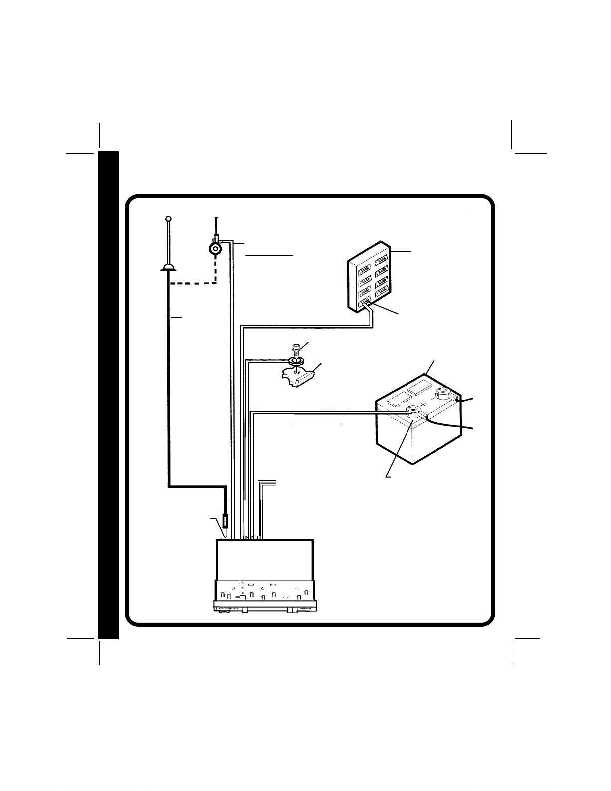
SCHÉMA DE CÂBLSCHÉMA DE CÂBL
SCHÉMA DE CÂBL
SCHÉMA DE CÂBLSCHÉMA DE CÂBL
VOIR CÂBLAGE DES HAUTS-PARLEURS PAGE 18
ANTENNE
AUTOMATIQUE
AA
A
AA
ANTENNE
GE DE L'AUTGE DE L'AUT
GE DE L'AUT
GE DE L'AUTGE DE L'AUT
OROR
OR
OROR
AA
A
AA
DIODIO
DIO
DIODIO
CÂBLAGE DE L'AUTORADIO
PRISE DE L'ANTENNE
À L'ARRIÈRE DE
L'AUTORADIO
CÂBLE
D'ANTENNE
EXISTANT
BLEU (FUSIBLE 0,5 A)
IMPORTANT
ON POURRA UTILISER DU FIL BLEU
POUR ACTIVER À DISTANCE UNE
ANTENNE AUTOMATIQUE OU POUR
ALLUMER UN AMPLI EXTÉRIEUR.
(REPORTEZ-VOUS À LA NOTICE
D'INSTALLATION DE L'ANTENNE OU
DE L'AMPLI.)
ROUGE (FUSIBLE 0,5 A)
VIS
NOIR
JAUNE (FUSIBLE 5 A)
CE FIL DOIT ÊTRE RELIÉ COMME
ILLUSTRÉ OU L'AUTORADIO NE FONCTIONNERA PAS CORRECTEMENT
IMPORTANT
VOIR CÂBLAGE DES
HAUT-PARLEURS
PAGE 18
PARTIE MÉTALLIQUE DU
TABLEAU DE BORD
(PERCEZ UN TROU LE
CAS ÉCHÉANT)
BOÎTE À FUSIBLES DU
VÉHICULE
FUSIBLE « AUTORADIO »
OU « ACCESSOIRE »
BATTERIE DU
VÉHICULE
BORNE POSITIVE (+)
DE LA BATTERIE
DE 12 VOLTS
33
3
33
1717
17
1717
AUTORADIO
128-5807B
18 of 44
Page 19

CÂBLAGE DESCÂBLAGE DES
CÂBLAGE DES
CÂBLAGE DESCÂBLAGE DES
HAUT-PARLEURSHAUT-PARLEURS
HAUT-PARLEURS
HAUT-PARLEURSHAUT-PARLEURS
VOIR CÂBLAGE DE
L'AUTORADIO PAGE 17
l LES AMPLIS DE CET AUTORADIO SONT UNIQUEMENT CONÇUS POUR UNE UTILISATION AVEC
4 HAUT-PARLEURS.
l NE JAMAIS COMBINER (PAR UN MONTAGE EN PONT) DES SORTIES POUR UNE UTILISATION
AVEC 2 HAUT-PARLEURS.
JAMAIS METTRE À LA MASSE LES CÂBLES NÉGATIFS DES HAUT-PARLEURS EN LES RELIANT
l NE
AU CHÂSSIS DE LA VOITURE.
l TOUT MAUVAIS CÂBLAGE EST SUSCEPTIBLE D'ENDOMMAGER L'AUTORADIO.
ATTENTION !
CÂBL
CÂBLCÂBL
CÂBLCÂBL
A
AA
AA
GE DES H
GE DES HGE DES H
GE DES HGE DES H
SORTIES RCA BAS
NIVEAU À
CONNECTER À UN/
DES AMPLI(S)
EXTÉRIEUR(S) EN
OPTION
ROUGE - ARRIÈRE
DROIT
BLANC - ARRIÈRE
GAUCHE
PRISES 9 BROCHES
HAUT-PARLEUR AVANT GAUCHE
BLANC AVEC RAYURE NOIRE
BLANC
AUTORADIO
REMARQUE :
CONSULTEZ VOTRE SPÉCIALISTE DES AUTORADIOS
RAMPAGE/AUDIOVOX OU APPELEZ LE 1-800-645-4994
POUR SAVOIR QUELS SONT LES MODÈLES COMPATIBLES AVEC VOTRE AUTORADIO.
CÂBLE DIN
(FOURNI AVEC LE
CHANGEUR DE CD)
PRISE DIN À 8 BROCHES POUR LE BRANCHEMENT
DU CHANGEUR DE CD EN OPTION
PRISES 4 BROCHES
VOIR CÂBLAGE DE
L'AUTORADIO PAGE 17
GRIS AVEC RAYURE NOIRE
GRIS
HAUT-PARLEUR AVANT DROIT
CHANGEUR DE CD
EN OPTION
6
COMPACT
AUT-P
AUT-PAUT-P
AUT-PAUT-P
A
AA
AA
RLEURS
RLEURSRLEURS
RLEURSRLEURS
VERT AVEC RAYURE NOIRE
HAUT-PARLEUR ARRIÈRE GAUCHE
VERT
VIOLET
VIOLET AVEC RAYURE NOIRE
DÉPANNAGE
1-800-645-49941-800-645-4994
1-800-645-4994
1-800-645-49941-800-645-4994
Du lundi au vendredi De 8 h 30 à 19 h 00, heure de l'Est
Le samedi De 9 h 00 à 17 h 00, heure de l'Est
HAUT-PARLEUR ARRIÈRE DROIT
128-5807B
19 of 44
1818
18
1818
Page 20

NONO
NO
NONO
IONION
IONION
ION
TT
TT
T
TT
ICE D'UTICE D'UT
T
ICE D'UT
TT
ICE D'UTICE D'UT
ILISAILISA
ILISA
ILISAILISA
TT
T
TT
IONION
ION
IONION
10
ILISAILISA
ILISAILISA
ILISA
ICE D'UTICE D'UT
ICE D'UTICE D'UT
ICE D'UT
TT
TT
T
NONO
NONO
NO
2
3
4
5
6
7
VOL
SEL
131617
ACD-16
BAND
VOL
AUX IN
26
CD- CD+ T/F
9
19
1 TOUCHE DE MARCHE-ARRÊT (PWR)
Appuyez sur cette touche pour allumer ou
éteindre l'appareil. L'appareil s'allume également automatiquement lorsque l'on insère un
disque compact, si le contact est mis.
2 TOUCHES DE RÉGLAGE DU VOLUME
(VOL / VOL )
Pour augmenter le volume, appuyez sur la
partie « vers le haut » de la touche. Le volume
augmentera et le niveau s'inscrira sur
l'afficheur, sa valeur étant comprise entre VOL
0 et VOL 63. Pour baisser le volume, appuyez
sur la partie « vers le bas » de la touche.
Maintenez la touche enfoncée pour baisser le
volume rapidement. L'affichage reviendra
automatiquement à l'indication normale 5
secondes après le dernier réglage du volume
ou lorsqu'une autre fonction sera activée. Cette
touche permet également, en conjonction avec
la touche de sélection
des basses, des aigus, de la balance et de
l'équilibreur avant-arrière, comme le décrivent
1919
19
1919
3, de régler le niveau
12
15
RND
24
MONLOU LOC/RPT
23
25
les sections
8
20
INT
22
4, 5, 6 et 7.
14
EJ
MUTE
N
I
N
U
TRACK
21
T
1
11
15
PWR
REL
G
18
3 SÉLECTEUR (SEL)
Cette touche permet de sélectionner la fonction
audio (volume, basses, aigus, balance ou
équilibreur avant-arrière) à régler à l'aide de la
touche de réglage du volume
unique sur le sélecteur permet d'accéder au
réglage du volume de l'appareil. Il est conseillé
d'utiliser la touche de réglage du volume
Deux pressions sur cette touche permettent
d'accéder au réglage des basses (BAS
s'affiche). Les pressions suivantes permettent
de sélectionner le réglage des aigus (TRE
s'affiche), de la balance (BAL) ou de l'équilibreur
avant-arrière (FAd). L'affichage reviendra
automatiquement à l'indication normale
5 secondes après le dernier réglage ou
lorsqu'une autre fonction sera activée.
2. Une pression
2.
4 RÉGLAGE DES BASSES
Pour régler le niveau des basses, commencez
par appuyer sur le sélecteur
3 de façon à ce
128-5807B
20 of 44
Page 21

que l'indication BAS s'affiche. Dans un délai de
5 secondes après avoir choisi le mode Basses,
appuyez sur la partie « vers le bas » de la
touche de réglage du volume
le niveau des basses ou sur la partie « vers le
haut » pour l'augmenter de la manière voulue.
Le niveau des basses s'affichera et sera
compris entre BAS -7 et BAS 7 (BAS 0
représentant la fidélité uniforme). L'affichage
reviendra automatiquement à l'indication
normale 5 secondes après le dernier réglage
ou lorsqu'une autre fonction sera activée.
2 pour diminuer
5 RÉGLAGE DES AIGUS
Pour régler le niveau des aigus, commencez
par sélectionner le mode Aigus en appuyant
sur le sélecteur
TRE s'affiche. Dans un délai de 5 secondes
après avoir choisi le mode Aigus, appuyez sur
la partie « vers le bas » de la touche de réglage
du volume
aigus ou sur la partie « vers le haut » pour
l'augmenter de la manière voulue. Le niveau
des aigus s'affichera et sera compris entre
TRE -7 et TRE 7 (TRE 0 représentant la fidélité
uniforme). L'affichage reviendra automatiquement à l'indication normale 5 secondes après
le dernier réglage ou lorsqu'une autre fonction
sera activée.
3 de façon à ce que l'indication
2 pour diminuer le niveau des
6 RÉGLAGE DE LA BALANCE
DROITE/GAUCHE
Pour régler la balance entre le haut-parleur
droit et le haut-parleur gauche, commencez
par sélectionner le mode Balance en appuyant
sur le sélecteur
BAL s'affiche. Dans un délai de 5 secondes
après avoir choisi ce mode, appuyez sur la
partie « vers le bas » de la touche de réglage
du volume
de la voie gauche, ou sur la partie « vers le
haut » de la touche pour privilégier les hautparleurs de la voie droite. Le niveau de la
balance s'affichera et sera compris entre
3 de façon à ce que l'indication
2 pour privilégier les haut-parleurs
BAL 10 (haut-parleurs droits coupés) et BAr 10
(haut-parleurs gauches coupés). Lorsque le
volume entre les haut-parleurs droit et gauche
est équilibré, l'afficheur indique BAL 0.
L'affichage revient automatiquement à l'indication normale 5 secondes après le dernier
réglage ou lorsqu'une autre fonction est activée.
7 RÉGLAGE DE L'ÉQUILIBREUR
AVANT/ARRIÈRE
Pour réaliser l'équilibrage entre les hautparleurs avant et arrière, commencez par
sélectionner le mode Équilibreur avant-arrière
en appuyant sur le sélecteur
que l'indication FAd s'affiche. Dans un délai de
5 secondes après avoir choisi ce mode,
appuyez sur la partie « vers le bas » de la
touche de réglage du volume
les haut-parleurs arrière, ou sur la partie « vers
le haut » de la touche pour privilégier les hautparleurs avant. La position de l'équilibreur
avant-arrière s'affichera et sera comprise entre
Far 10 (haut-parleurs avant coupés) et FAF 10
(haut-parleurs arrière coupés). Lorsque le
niveau des haut-parleurs avant et arrière est
équilibré, l'afficheur indique FAd 0. L'affichage
revient automatiquement à l'indication normale
5 secondes après le dernier réglage ou
lorsqu'une autre fonction est activée.
3 de façon à ce
2 pour privilégier
8 RECHERCHE DE PLAGE
(PLAGE / PLAGE )
La fonction de recherche de plage permet de
se rendre rapidement au début de la plage
voulue lorsque l'on utilise le lecteur ou le
changeur de CD. Chaque brève pression sur
la partie « vers l'avant » (PLAGE
de défilement des plages sélectionne la plage
suivante et son numéro s'affiche. De la même
façon, chaque brève pression sur la partie
« vers l'arrière » (PLAGE
sélectionne la plage précédente et son numéro
s'affiche.
) de la touche
) de la touche
NO
NONO
NONO
T
TT
TT
ICE D'UT
ICE D'UTICE D'UT
ICE D'UTICE D'UT
ILISA
ILISAILISA
ILISAILISA
T
TT
TT
ION
IONION
IONION
2020
20
2020
77
7
77
128-5807B
21 of 44
Page 22

9 SÉLECTION DU CD (CD- CD+)
IONION
IONION
ION
Lorsque l'on utilise le changeur de CD, cette
TT
TT
T
touche permet de sélectionner le disque
compact que l'on veut écouter. Pour choisir un
ILISAILISA
ILISAILISA
ILISA
disque portant un numéro supérieur, appuyez
sur la touche CD+. Pour choisir un disque
portant un numéro inférieur, appuyez sur la
touche CD-. Le numéro du disque en cours de
lecture sera affiché.
ICE D'UTICE D'UT
ICE D'UTICE D'UT
ICE D'UT
TT
TT
T
bl SÉLECTEUR DE LECTURE /
NONO
NONO
NO
PAUSE DU CD ( )
Appuyez sur cette touche pour interrompre
momentanément la lecture d'un disque
compact lorsque vous utilisez le lecteur ou le
changeur de CD (l'indication
l'afficheur). Appuyez de nouveau sur la touche
pour reprendre la lecture là où elle avait été
interrompue.
bm VOLUME DE LA MISE EN
SOURDINE (MUTE)
Appuyez sur cette touche pour mettre l'appareil
en sourdine (l'indication MUTE s'affiche). Une
nouvelle pression sur cette touche ou sur la
touche de réglage du volume
l'appareil au volume qui était utilisé avant
l'activation de la fonction Mise en sourdine.
2 fait revenir
bn AFFICHEUR À CRISTAUX LIQUIDES
L'afficheur à cristaux liquides (ACL) affiche la
fréquence et les fonctions activées.
REMARQUE : Les afficheurs à cristaux
liquides présentent la particularité, s'ils sont soumis à
des températures basses
pendant des périodes prolongées, de mettre plus de temps
à s'allumer que dans des
conditions normales. La visibilité des chiffres peut égale-
2121
21
2121
ment s'en trouver légèrement
affectée. L'afficha-ge à cristaux
clignote sur
liquides redevient normal
lorsque la température se
normalise.
bo FENTE D'INSERTION DU
DISQUE COMPACT
Tenez le disque compact étiquette vers le haut
et introduisez-le entièrement dans la fente
jusqu'à ce que le mécanisme s'engage et
aspire le disque. L'indication LOAdCd s'affiche
brièvement suivie de l'indication CdP et de la
durée de lecture du disque. Puis la lecture
commence et le numéro de la plage s'affiche
ainsi que le symbole représentant un disque
qui tourne (
REMARQUE : Cet appareil est conçu pour la
).
lecture des disques compacts
standard de 12 cm (5")
MENT. Ne tentez pas d'utiliser
des mini-disques de 8 cm (3")
sur cet appareil, que ce soit
avec ou sans adaptateur, car
cela pourrait endommager le
lecteur et/ou le disque. De tels
dommages ne seront pas
couverts par la Garantie de
l'appareil.
UNIQUE-
bp ÉJECTION DU DISQUE
COMPACT (EJ)
En appuyant sur cette touche, la lecture du
disque compact s'interrompt et le disque
est éjecté (EJCd s'affiche). Retirez le disque
et insérez un autre disque dans l'appareil
pour en commencer la lecture ou appuyez
sur le sélecteur de fonction (Mode) cm pour
sélectionner le mode radio ou changeur de
CD. Les disques sont éjectés lorsque l'on
presse la touche et que le contact est mis.
Le fonctionnement de la radio ou du changeur
de CD reprend automatiquement suivant le
mode qui était sélectionné avant la lecture du
disque. Si le disque compact n'est pas retiré
128-5807B
22 of 44
Page 23

de l'appareil dans un délai de 10 secondes
après avoir été éjecté, il sera automatiquement
réinséré dans l'appareil pour éviter qu'il ne
s'abîme (
disque est inséré dans l'appareil). On peut
reprendre la lecture du disque en sélectionnant
la fonction lecteur de CD au moyen du sélecteur
de fonction (Mode)
REMARQUE : Toujours retirer un disque
s'affichera pour indiquer qu'un
cm.
éjecté de l'appareil pour éviter
qu'il ne soit endommagé
accidentellement. Ne pas
laisser le disque dépasser de
la fente d'insertion.
S'assurer qu'il n'y a pas de poussière ni de
saletés sur les bornes situées au dos de la
façade car cela pourrait provoquer un faux
contact ou tout autre mauvais fonctionnement.
br VOYANT DEL DE PRÉVENTION
DU VOL
Une diode électroluminescente (DEL) située
sur le châssis, derrière la façade, clignote
lorsque cette dernière est enlevée. Le voyant
clignotant sert à indiquer aux voleurs éventuels
que l'appareil a été mis hors service en retirant
la façade.
NO
NONO
NONO
T
TT
TT
ICE D'UT
ICE D'UTICE D'UT
ICE D'UTICE D'UT
ILISA
ILISAILISA
ILISAILISA
T
TT
TT
ION
IONION
IONION
bq BOUTON DE VERROUILLAGE
DE LA FAÇADE (REL)
Ce bouton permet de déverrouiller le mécanisme retenant la façade au châssis. Pour
détacher la façade, appuyez sur le bouton de
façon à libérer cette dernière du châssis.
Saisissez-la en son milieu et retirez-la du
châssis.
Pour remettre la façade, mettez tout d'abord en
place la partie gauche (lorsque vous faites face
à l'autoradio), puis appuyez sur la partie droite
jusqu'au déclic du mécanisme de verrouillage.
REMARQUES SUR L'UTILISATION
DE LA FAÇADE
1. S'assurer que la façade est bien à l'endroit
en la fixant au châssis car on ne peut pas
la fixer lorsqu'elle est à l'envers.
2. Ne pas appuyer pas trop fort sur la façade
en la fixant au châssis. Une pression légère
ou moyenne devrait suffire.
3. En installant la façade, s'assurer de bien
placer celle-ci en face du châssis et de ne
pas l'emboîter de travers.
4. En emportant la façade avec soi, utiliser la
housse de transport fournie pour ne pas
l'abîmer et la protéger de la poussière.
bs BOUTON DE RÉINITIALISATION
Un bouton de réinitialisation est situé sur le
devant du châssis (la façade doit avoir été
enlevée pour pouvoir y accéder). Les circuits
de réinitialisation sont là pour protéger les
circuits du microprocesseur et ne doivent être
activés que dans les circonstances suivantes
car ils effacent l'heure et les présélections.
1. Après l'installation initiale, une fois tous
les câblages effectués.
2. Si un sélecteur quelconque de l'appareil
fonctionne mal, appuyer sur le bouton de
réinitialisation permet de remettre le
système à zéro et de revenir à un
fonctionnement normal.
bt BOUTON DE SYNTONISATION
MANUELLE
Tournez ce bouton dans le sens des aiguilles
d'une montre pour syntoniser dans le sens
des fréquences croissantes, et dans le sens
inverse des aiguilles d'une montre pour
syntoniser dans le sens des fréquences
décroissantes. La fréquence sur laquelle
l'accord est fait s'affiche sous forme numérique.
En faisant l'accord sur une station, réglez
toujours l'appareil de façon à ce que la fréquence
exacte d'émission s'affiche et effectuez les
2222
22
2222
128-5807B
23 of 44
Page 24

réglages de manière à ce que la réception soit
bonne. Si l'autoradio n'est pas réglé exactement
sur la bonne fréquence, il sera possible
d'entendre des distorsions, du bruit ou d'avoir
d'autres problèmes de réception.
bu SÉLECTEUR DE BANDE
AM/FM (BAND)
Chaque brève pression sur cette touche
change de bande radio. L'indication AM ou FM
s'inscrira sur l'afficheur suivant votre sélection.
NOTICE D'UTILISATION
cl INDICATEUR DE VOLUME
Cet affichage est constitué de deux barres
composées de plusieurs bâtonnets indiquant
le niveau du signal audio. Le nombre de
bâtonnets présents sur chacune des barres
correspond au niveau du signal audio (plus il
y a de bâtonnets, plus le signal est puissant).
Lorsque l'on utilise le lecteur ou le changeur de
CD, l'affichage indique le niveau du signal
audio du CD.
cm SÉLECTEUR DE FONCTION (MODE)
Cette touche permet de sélectionner le mode
lecture (radio, lecteur de CD ou changeur de
CD en option). Chaque brève pression sur
cette touche sélectionne un mode de lecture
différent qui s'affiche.
Radio (FM ou AM sur l'affichage)
CD (CdP sur l'affichage)
(CdC sur l'affichage).
Lors de la lecture d'un disque compact, il est
possible d'utiliser cette touche pour passer en
mode radio ou changeur de CD sans éjecter
le disque.
[ lecteur de
[ changeur de CD
cn SÉLECTEUR D'HEURE/
FRÉQUENCE (T/F)
Lorsque vous écoutez la radio, appuyez sur
cette touche pour afficher l'heure de la montre
à quartz intégrée. L'affichage reviendra à la
fréquence radio au bout de 5 secondes.
2323
23
2323
Lorsque vous utilisez le lecteur ou le changeur
de CD, la première pression sur cette touche
affiche l'heure. L'affichage reviendra au
numéro du disque au bout de 5 secondes,
que vous utilisiez le lecteur ou le changeur de
CD.
co SÉLECTEUR LOCAL/ RÉPÉTITION
(LOC/RPT)
Lorsque vous écoutez la radio, une pression
sur cette touche permet de sélectionner le
réglage local pour la réception des signaux
puissants. L'indication LOC s'inscrira sur
l'afficheur. Une nouvelle pression sur la touche
désactive la fonction.
Lorsque vous utilisez le lecteur ou le changeur
de CD, une pression sur cette touche permet
de répéter la lecture de la plage en cours.
L'indication RPT s'affiche. Une nouvelle
pression sur la touche désactive la fonction.
cp SÉLECTEUR DE COMPENSATION
PHYSIOLOGIQUE/ LECTURE
ALÉATOIRE (LOUD/RND)
Lorsque vous écoutez de la musique à faible
volume, à la radio ou sur un CD, cette fonction
accentue les fréquences basses et aiguës de
façon à compenser les insuffisances de l'oreille
humaine. Appuyez brièvement sur le sélecteur
pour activer cette fonction ; l'indication LOUD
s'inscrit sur l'afficheur. Une nouvelle pression
brève sur la touche désactive la fonction
(l'indication LOUD s'efface). Lorsque vous
utilisez le lecteur ou le changeur de CD, appuyer
sur le sélecteur durant plusieurs secondes
permet au lecteur et au changeur de CD de lire
les plages des CD dans un ordre aléatoire.
L'indication RND s'affiche. Appuyer de nouveau
sur le sélecteur pendant plusieurs secondes
désactive la fonction.
128-5807B
24 of 44
Page 25

cq ÉCOUTE DE LA RADIO EN MONO/
BALAYAGE DES INTRODUCTIONS
DES PLAGES ( MON/INT)
Lorsque l'on écoute la radio sur la bande FM,
cette touche permet de sélectionner la réception
mono ou stéréo du signal d'émission. Dans
des conditions de réception normales,
l'appareil doit rester en mode stéréo ; la mention
sur l'afficheur indique que l'on est réglé
ST
sur un signal FM stéréo. Si le signal stéréo est
trop bruité pour une écoute agréable, appuyez
sur le sélecteur FM Mono/Stéréo pour passer
à une réception mono (l'indication ST
s'efface). Pour revenir au mode de réception
stéréo, appuyez de nouveau sur la touche de
façon à ce que l'indication ST
Pendant la lecture d'un disque compact ou
lorsque vous utilisez le changeur de CD en
option, appuyez sur cette touche pour lire les
10 premières secondes de chaque plage du
s'affiche.
disque compact (l'indication INT s'affiche).
Lorsque vous avez trouvé la plage souhaitée,
appuyez de nouveau sur la touche pour
désactiver la fonction (l'indication INT s'efface)
et la lecture de la plage sélectionnée se
poursuivra. Le mode Balayage des introductions des plages pourra également être
désactivé en activant la fonction de répétition
co.
cr PRISE D'ENTRÉE AUXILIAIRE
La prise d'entrée auxiliaire donne à l'utilisateur
l'option de brancher l'autoradio sur une source
extérieure. La prise est compatible avec la
plupart des lecteurs de CD et de cassettes
portatifs ou avec un lecteur numérique MP3.
Lorsque la source extérieure est branchée,
seul ce support est lu par l'autoradio ; aucune
autre source d'entrée (radio ou CD) n'est
opérante.
NO
NONO
NONO
T
TT
TT
ICE D'UT
ICE D'UTICE D'UT
ICE D'UTICE D'UT
ILISA
ILISAILISA
ILISAILISA
T
TT
TT
ION
IONION
IONION
128-5807B
25 of 44
2424
24
2424
Page 26
RÉGLRÉGL
AA
RÉGL
RÉGLRÉGL
1. Mettez le contact du véhicule et allumez l'autoradio.
Appuyez sur le sélecteur d'heure/fréquence de façon à afficher l'heure.
Maintenez le sélecteur d'heure/fréquence cn enfoncé alors que l'heure est affichée.
L'affichage de l'heure se met à clignoter.
4. Appuyez sur la touche VOL pour régler les heures et l'indication AM/PM, et sur la
touche VOL pour régler les minutes.
Cinq secondes après le dernier réglage des heures ou des minutes, l'heure est
mémorisée et l'appareil revient à l'affichage normal.
GE DE LGE DE L
A
GE DE L
AA
GE DE LGE DE L
A MONTREA MONTRE
A MONTRE
A MONTREA MONTRE
CODES D'ERREUR DU LECCODES D'ERREUR DU LEC
CODES D'ERREUR DU LEC
CODES D'ERREUR DU LECCODES D'ERREUR DU LEC
ER-1 : Indique une température excessive au niveau du changeur de CD. Le code d'erreur
A MONTRE/ CODES D'ERREURA MONTRE/ CODES D'ERREUR
A MONTRE/ CODES D'ERREURA MONTRE/ CODES D'ERREUR
A MONTRE/ CODES D'ERREUR
ER-2 : Indique un problème d'insertion ou d'éjection du disque, essayez de réinsérer le
GE DE LGE DE L
GE DE LGE DE L
GE DE L
AA
AA
A
ER-3 : Ne peut pas être réparé par l'utilisateur, contactez un centre de garantie agréé
RÉGLRÉGL
RÉGLRÉGL
RÉGL
ER-4 : Ne peut pas être réparé par l'utilisateur, contactez un centre de garantie agréé
ER-5 : Ne peut pas être réparé par l'utilisateur, contactez un centre de garantie agréé
ER-6 : Ne peut pas être réparé par l'utilisateur, contactez un centre de garantie agréé
ER-7 : Ne peut pas être réparé par l'utilisateur, contactez un centre de garantie agréé
ER-8 : Ne peut pas être réparé par l'utilisateur, contactez un centre de garantie agréé
ER-9 : Éjectez le disque, assurez-vous qu'il est propre, qu'il n'est pas abîmé et qu'il a été
ER-10 : Ne peut pas être réparé par l'utilisateur, contactez un centre de garantie agréé
ER-11 : Indique qu'il n'y a pas de magasin dans le changeur de CD.
2525
25
2525
s'effacera et la lecture reprendra lorsque la température redeviendra normale au
niveau du changeur de CD.
disque ou d'appuyer sur la touche d'éjection. Vérifiez l'état du disque ou essayezen un autre.
près de chez vous pour une assistance supplémentaire.
près de chez vous pour une assistance supplémentaire.
près de chez vous pour une assistance supplémentaire.
près de chez vous pour une assistance supplémentaire.
près de chez vous pour une assistance supplémentaire.
près de chez vous pour une assistance supplémentaire.
inséré correctement (étiquette vers le haut).
près de chez vous pour une assistance supplémentaire.
TEUR DE CDTEUR DE CD
TEUR DE CD
TEUR DE CDTEUR DE CD
128-5807B
26 of 44
Page 27

CARACTÉRISTIQUES TECHNIQUESCARACTÉRISTIQUES TECHNIQUES
CARACTÉRISTIQUES TECHNIQUES
CARACTÉRISTIQUES TECHNIQUESCARACTÉRISTIQUES TECHNIQUES
CARACTÉRISTIQUES TECHNIQUES
Dimensions :
Tension de fonctionnement :
Calibres des fusibles :
Puissance de sortie :
Câblage de sortie :
Impédance de sortie :
Gamme d'accord :
Sensibilité :
Séparation des canaux FM :
Réponse en fréquence du CD :
Rapport signal bruit du CD :
Séparation des voies du CD :
178 (L) x 50 (H) x 155 (P) mm
7" (L) x 2" (H) x 6 1/8"(P)
12 volts c.c., masse négative
Constant (jaune) : 5 A
Commuté (rouge) : 0,5 A
60 watts maximum
(4 x 15 watts)
Type circuit commun isolé de la masse conçu
pour 4 haut-parleurs.
Compatible avec des haut-parleurs de 4 à 8 ohms
AM : 530 - 1 720 KHz
FM : 87.5 - 107.9 MHz
AM : 20 µv
FM : 1,5 µv
>25 dB
20 - 20 000 Hz ± 1 dB
>60 dB
>60 dB
Distorsion du CD :
*Les caractéristiques techniques sont susceptibles d'être modifiées sans préavis.
LECTURE DES CD-R ET DES CD-RW
Ce modele peut lire la plupart des medias CD-R et CD-RW contenant des programmes
audio.
La lecture des CD-R et des CD-RW depend de l’etat du materiel d’enregistrement et de
la qualite du disque CD-R ou CD-RW. Il arrive parfois qu’un disque CD-R ou CD-RW ne
puisse pas etre lu sur cet appareil.
0,2 %
128-5807B
27 of 44
2626
26
2626
Page 28

PRÉCAUTIONS ET ENTRETIENPRÉCAUTIONS ET ENTRETIEN
PRÉCAUTIONS ET ENTRETIEN
PRÉCAUTIONS ET ENTRETIENPRÉCAUTIONS ET ENTRETIEN
IENIEN
IENIEN
IEN
La partie autoradio de votre nouvelle chaîne stéréo ne nécessite aucun entretien. Nous vous conseillons
de conserver ce manuel pour vous reporter ultérieurement aux nombreuses fonctions de cet appareil
ainsi qu'au réglage de la montre.
La partie lecteur de disque compact ne requiert pas non plus d'entretien régulier, mais bien comprendre
son fonctionnement et sa manipulation vous permettra de profiter au maximum de ses capacités. Les
points suivants devront être observés :
l En nettoyant l'intérieur du véhicule, n'aspergez pas l'appareil d'eau ou de liquides de nettoyage.
l Le lecteur de CD est un instrument de précision et il ne fonctionnera pas correctement par des
températures extrêmes. Dans de telles conditions, attendez que l'habitacle revienne à une
température normale avant d'utiliser le lecteur.
IONS ET ENTRETIONS ET ENTRET
IONS ET ENTRETIONS ET ENTRET
IONS ET ENTRET
l Si le lecteur chauffe trop, un circuit de protection interrompt automatiquement la lecture du disque
compact. Dans ce cas, laissez l'appareil refroidir avant de réutiliser le lecteur.
l N'introduisez jamais autre chose qu'un disque compact de 12 cm (5") dans le lecteur car le mécanisme
peut être endommagé par des corps étrangers.
l Ne tentez pas d'utiliser de mini-disques de 8 cm (3") sur cet appareil, que ce soit avec ou sans
PRÉCAUTPRÉCAUT
PRÉCAUTPRÉCAUT
PRÉCAUT
adaptateur, car cela pourrait endommager le lecteur et/ou le disque compact. De tels dommages ne
seront pas couverts par la Garantie de l'appareil.
l Lorsque le lecteur n'est pas en service, retirez toujours le disque compact. Ne laissez pas le disque
éjecté dans la fente d'insertion car il pourrait être exposé à la lumière du soleil et à d'autres agents
susceptibles de l'endommager.
l Ne tentez pas d'ouvrir le châssis de l'appareil. Il ne contient pas de pièces pouvant être réparées par
l'utilisateur ni de réglages.
l Lorsque le véhicule se réchauffe par temps froid ou humide, l'humidité peut se condenser sur la lentille
du lecteur de disque compact. Si tel est le cas, le lecteur ne fonctionnera pas correctement avant que
l'humidité se soit évaporée.
l L'appareil est doté d'un mécanisme d'absorption des vibrations du CD de façon à minimiser les
interruptions de lecture dues aux vibrations normales d'un véhicule en mouvement. Sur des routes
particulièrement cahoteuses, cependant, le son pourra parfois sauter. Cela ne rayera pas et
n'abîmera pas le disque compact et la lecture normale reprendra dès que l'état de la route s'améliorera.
MANIPULATION DES DISQUES COMPACTS
Un disque sale, poussiéreux, rayé ou gondolé peut provoquer des sautes de lecture et réduire la qualité
sonore. Veuillez suivre les recommandations suivantes pour l'entretien de vos disques compacts :
l Utilisez uniquement des disques compacts portant la marque
l Les traces de doigts, la poussière et la saleté devront être minutieusement essuyées de la surface de
lecture du disque compact (face brillante) à l'aide d'un chiffon doux. Essuyez de l'intérieur vers
l'extérieur du disque, selon un mouvement linéaire.
l N'utilisez jamais de produits chimiques, tels que des aérosols pour disques en vinyle, des produits
d'entretien ménagers ou du diluant pour nettoyer vos disques compacts. De tels produits peuvent
endommager de manière irréversible la surface du disque.
l Les disques compacts doivent être conservés dans leurs boîtiers lorsqu'ils ne sont pas utilisés.
l N'exposez pas les disques compacts aux rayons du soleil, à des températures élevées ou à une trop
grande humidité pendant des périodes prolongées.
l Ne collez pas de papier, de ruban adhésif ou d'étiquettes sur les surfaces du disque compact et
2727
27
2727
n'écrivez pas non plus dessus au marqueur.
128-5807B
28 of 44
Page 29
GG
AA
RR
AA
NTNT
A
AA
IE LIMIIE LIMI
NT
IE LIMI
NTNT
IE LIMIIE LIMI
G
A
R
GG
AA
RR
AUDIOVOX CORPORATION (ci-après, « la Société ») garantit au premier acheteur au détail de cet
appareil, que si, dans des conditions normales d'utilisation, il est démontré que cet appareil, ou une
quelconque de ses pièces, présente un ou des défauts de matériaux ou de fabrication dans un délai
de 12 mois à compter de la date du premier achat, le ou lesdits défauts seront réparés, ou la ou les pièces
défectueuses remplacées par des pièces neuves ou remises à neuf (à la discrétion de la Société) sans
frais à acquitter pour les pièces ou la main d'œuvre.
Pour pouvoir bénéficier des réparations ou du remplacement dans la limite des conditions de la présente
Garantie, l'appareil doit être livré accompagné d'une preuve d'achat (par ex. une facture datée), de la
description du ou des défauts, en port payé, à un centre de Garantie agréé ou à la Société à l'adresse
indiquée ci-dessous.
La présente Garantie ne s'étend pas à l'élimination des parasites ou du souffle générés par le véhicule,
ni à la correction de problèmes d'antenne, ni aux frais engagés pour l'installation, le retrait ou la
réinstallation de l'appareil, ni à l'endommagement des cassettes, des disques compacts, des hautparleurs, des accessoires ou des circuits électriques du véhicule.
La présente Garantie ne s'applique à aucun appareil ou pièce de ce dernier ayant été, selon la Société,
endommagé suite à des modifications, à une mauvaise installation, à une mauvaise manipulation, à un
emploi abusif, à une négligence, à un accident ou à un retrait ou une mutilation de la ou des étiquettes
de l'usine où figure le numéro de série/code barre. L'ÉTENDUE DE LA RESPONSABILITÉ DE LA SOCIÉTÉ
EN VERTU DE LA PRÉSENTE GARANTIE SE LIMITE À LA RÉPARATION OU AU REMPLACEMENT PRÉVUS
CI-DESSUS ET N'EXCÉDERA EN AUCUN CAS LE MONTANT PAYÉ PAR L'ACHETEUR POUR L'APPAREIL.
La présente Garantie remplace toute autre garantie ou responsabilité expresse. TOUTE GARANTIE
EXPRESSE OU TACITE, Y COMPRIS TOUTE GARANTIE TACITE DE QUALITÉ MARCHANDE, SERA LIMITÉE
À LA DURÉE DE LA PRÉSENTE GARANTIE ÉCRITE. TOUTE ACTION EN JUSTICE POUR INOBSERVATION
D'UNE QUELCONQUE GARANTIE EN VERTU DES PRÉSENTES, Y COMPRIS DE TOUTE GARANTIE TACITE
DE QUALITÉ MARCHANDE, DEVRA ÊTRE INTENTÉE DANS UN DÉLAI DE 30 MOIS À COMPTER DE LA
DATE DU PREMIER ACHAT. EN AUCUN CAS LA SOCIÉTÉ NE SERA RESPONSABLE DE QUELQUE
DOMMAGE CONSÉCUTIF OU INDIRECT QUE CE SOIT, DÛ À L'INOBSERVATION DE LA PRÉSENTE
GARANTIE OU DE TOUTE AUTRE GARANTIE, EXPRESSE OU TACITE, QUELLE QU'ELLE SOIT. Aucune
personne ni représentant n'est autorisé à assumer au nom de la Société une quelconque responsabilité
autre que celle formulée aux présentes en rapport avec la vente de cet appareil.
Certains États n'autorisent pas les limitations de durée sur les garanties tacites, ni l'exclusion des
dommages indirects ou consécutifs ou les restrictions les concernant, les restrictions ou exclusions
ci-dessus ne s'appliquent donc peut-être pas à votre cas. La présente Garantie vous donne certains
droits légaux spécifiques ; il est également possible que vous ayez d'autres droits qui peuvent varier
selon les États.
ÉTATS-UNIS : AUDIOVOX CORPORATION, 150 MARCUS BLVD, HAUPPAUGE, NEW YORK 11788 o
1-800-645-4994
CANADA : APPELEZ LE 1-800-645-4994 POUR OBTENIR L'ADRESSE D'UN CENTRE DE GARANTIE
DESSERVANT VOTRE RÉGION.
TÉE DE 12 MOISTÉE DE 12 MOIS
TÉE DE 12 MOIS
TÉE DE 12 MOISTÉE DE 12 MOIS
Formulaire nº 128-42706
G
GG
GG
A
AA
AA
R
RR
RR
A
AA
AA
NT
NTNT
NTNT
IE
IEIE
IEIE
128-5807B
29 of 44
2828
28
2828
Page 30

INSTRUCCIONES PARA LA INSTALACIÓNINSTRUCCIONES PARA LA INSTALACIÓN
INSTRUCCIONES PARA LA INSTALACIÓN
Esta unidad está diseñada para ser instalada en automóviles, camiones y camionetas que ya tengan una abertura para
radio. En muchos casos, se necesitará un equipo de instalación especial para montar la radio en el tablero de instrumentos.
Se puede conseguir estos equipos en las tiendas de artículos electrónicos y en los negocios especializados en equipos
ACIÓNACIÓN
ACIÓNACIÓN
ACIÓN
estereofónicos para automóviles. Antes de comprar el equipo averigüe para qué aplicaciones está destinado el mismo para
asegurarse de que sirva para su vehículo. Si no puede encontrar el equipo que necesita, llame a nuestra línea gratuita de
ALAL
ALAL
AL
AYUDA al 1-800-645-4994.
PROCEDIMIENTO DE INSTALACIÓN UNIVERSAL CON MANGA DE MONTAJE
1. Deslice la manga de montaje para retirarla del chasis. Si está trabada en su lugar, use las herramientas de extracción
(provistas) para desengancharla.
A INSTA INST
A INSTA INST
A INST
2. Coloque la manga de montaje para verificar el tamaño de la abertura que hay en el tablero de instrumentos. Si la abertura
es pequeña, corte o lime con cuidado lo que fuese necesario hasta que la manga de montaje calce fácilmente en la abertura.
A LA L
A LA L
A L
No fuerce la manga en la abertura, tampoco la doble ni arquee. Asegúrese de tener espacio suficiente detrás del tablero
de instrumentos para el chasis de la radio.
RR
RR
R
3. Ubique las series de lengüetas a lo largo de la parte superior, inferior y los lados de la manga de montaje. Con la manga
AA
AA
A
de montaje totalmente colocada dentro de la abertura del tablero de instrumentos, doble hacia afuera todas la lengüetas
que sea necesario para asegurar firmemente la manga al tablero.
4. Coloque la radio frente a la abertura del tablero de instrumentos para poder pasar el cableado a través de la manga de
montaje. Siga cuidadosamente el diagrama de cableado y asegúrese de que todas las conexiones del arnés de cableado
estén seguras y aisladas con tuercas para alambre o cinta aislante para procurar el funcionamiento correcto de la unidad.
Después de terminar las conexiones de cableado, encienda la unidad para confirmar su funcionamiento (la llave de contacto
debe estar en "on"). Si la unidad no funciona, revise el cableado hasta que corrija el problema.
NOTA: Ajuste el compensador de antena AM EN ESTE MOMENTO. Las instrucciones de ajuste se encuentran en una
etiqueta a la derecha del chasis. Una vez logrado el funcionamiento correcto, apague la llave de contacto y proceda
5. Deslice con cuidado la radio en la manga de montaje, asegúrese de que esté en la posición correcta, hasta que esté
INSTRUCCIONES PINSTRUCCIONES P
INSTRUCCIONES PINSTRUCCIONES P
INSTRUCCIONES P
6. Fije un extremo de la correa de soporte perforada (provista) al tornillo que se encuentra en la parte posterior del chasis
7. Consulte las Instrucciones de funcionamiento para probar el funcionamiento de la radio.
LOS JUEGOS DE INSTALACIÓN
1. Si el vehículo requiere el uso de un juego de instalación para montar la radio, siga las instrucciones incluidas en el juego de
2. Haga las conexiones de cables y pruebe la radio según se describe en el Paso 4 anterior.
3. Instale el conjunto formado por radio/placa de montaje en el subtablero, de acuerdo con las instrucciones del juego de instalación.
4. Fije la correa de soporte a la radio y al tablero de instrumentos según se describe en el Paso 6 anterior.
5. Vuelva a colocar el panel de reborde del tablero.
PROCEDIMIENTO DE INSTALACIÓN ISO
Esta unidad tiene orificios roscados en los paneles laterales del chasis que pueden usarse con los soportes de montaje originales
de fábrica de algunos vehículos Toyota, Nissan, Mitsubishi, Isuzu, Hyundai y Honda para montar la radio al tablero. Sírvase
consultar a la tienda local que sea especialista en equipos estereofónicos para automóviles así consigue asistencia para este
tipo de instalación.
1. Quite la radio que venga de fábrica en el tablero de instrumentos o en la consola central. Guarde todas las piezas, tornillos
2. Desenganche con cuidado el armazón de plástico de la parte delantera del chasis de la radio nueva. Quite y descarte el
3. Quite los soportes de montaje que vengan de fábrica y los tornillos de la radio y úselos para la radio nueva.
2929
29
2929
4. Conecte los cables de la radio nueva al vehículo según lo indicado en el paso 4 anterior.
5. Monte la radio nueva al tablero de instrumentos o a la consola central, para lo cual siga el procedimiento inverso al paso 1.
con el montaje final del chasis.
totalmente asentada y los soportes antivibratorios trabados en su lugar.
con la tuerca hexagonal provista. Ajuste el otro extremo de la correa perforada a una parte segura del tablero de
instrumentos, ya sea por encima o por debajo de la radio, con el tornillo provisto. Doble la correa para ubicarla si es necesario.
PRECAUCIÓN: La parte posterior de la radio debe estar apoyada sobre la correa para evitar daños al tablero como
instalación para colocar la radio en la placa de montaje provista con el mismo.
y soportes ya que los usará para montar la radio nueva.
armazón.
PRECAUCIÓN: NO EXCEDA EL TAMAÑO MÁXIMO DE TORNILLO M5 X 6 MM.
INSTRUCCIONES PARA LA INSTALACIÓNINSTRUCCIONES PARA LA INSTALACIÓN
consecuencia del peso de la radio o el uso incorrecto debido a la vibración.
SI LOS TORNILLOS SON MÁS LARGOS, PUEDEN TOCAR Y DAÑAR LOS COMPONENTES QUE
ESTÉN ADENTRO DEL CHASIS.
128-5807B
30 of 44
Page 31
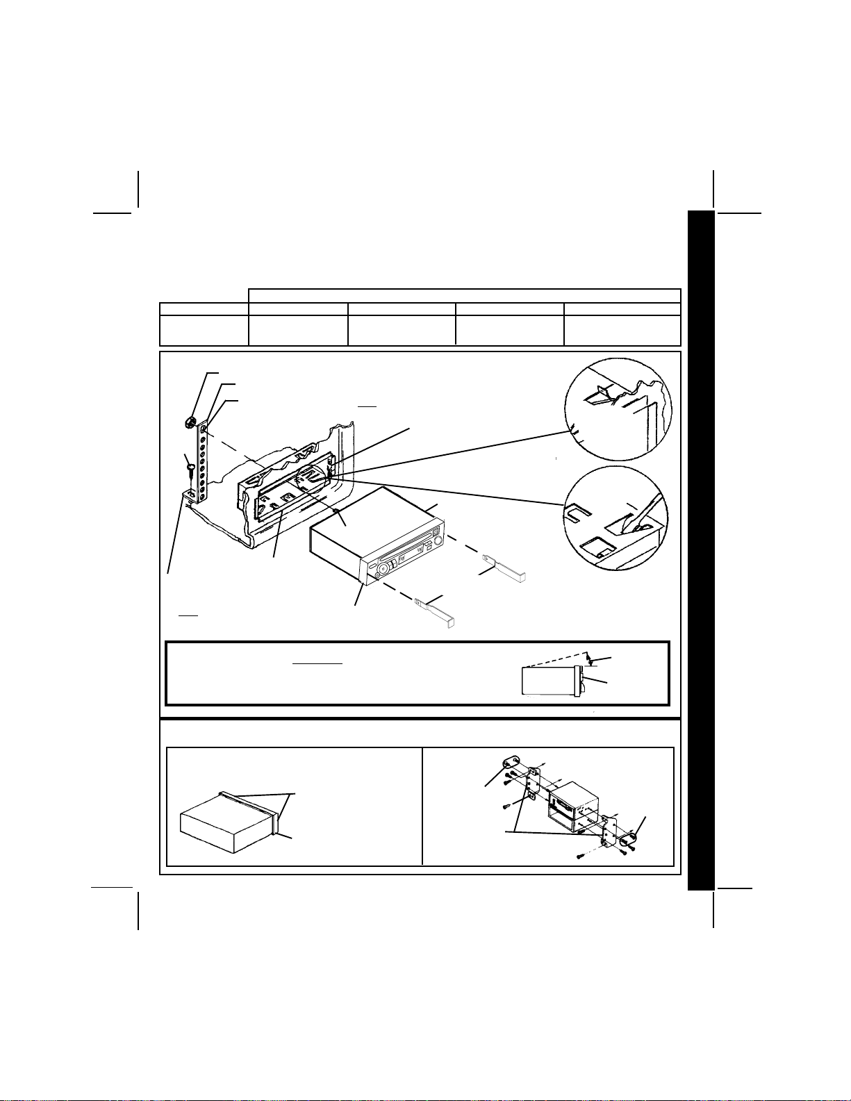
ASISTENCIASISTENCI
ASISTENCI
ASISTENCIASISTENCI
La instalación y las conexiones de los cables de esta unidad son muy sencillos, por lo tanto dudamos de que tenga alguna
duda o necesite ayuda, pero si tiene problemas, estamos a su disposición para prestarle ayuda. Simplemente llame a nuestro
teléfono gratuito de asistencia, 1-800-645-4994, durante los días y las horas que se indican (EE.UU. y Canadá solamente).
A GRA GR
A GR
A GRA GR
AA
A
AA
TUITUI
TUI
TUITUI
TT
T
TT
A PA P
A P
A PA P
AA
RR
A LA L
R
RR
A L
A LA L
A INSTA INST
A INST
A INSTA INST
A
AA
ALAL
AL
ALAL
ACIÓNACIÓN
ACIÓN
ACIÓNACIÓN
INSTRUCCIONES P
INSTRUCCIONES PINSTRUCCIONES P
INSTRUCCIONES PINSTRUCCIONES P
DÍA
LUN VIE
SÁBADO
TORNILLO
(5MM)
FIJE ESTE EXTREMO PARA ASEGURAR
LA PIEZA AL TABLERO - PERFORE EL
AGUJERO SI ES NECESARIO.
NOTA: DEBE QUITAR LA ESTRUCTURA DE PLÁSTICO (DESENGANCHE LOS LADOS IZQUIERDO Y DERECHO) PARA USAR LAS HERRAMIENTAS DE EXTRACCIÓN.
PARA QUE EL REPRODUCTOR DE DISCOS COMPACTOS FUNCIONE
CORRECTAMENTE, DEBE MONTAR EL CHASIS A NO MÁS DE 20º DE INCLINACIÓN,
ASEGÚRESE DE QUE LA UNIDAD ESTÉ MONTADA DENTRO DE ESE LÍMITE.
ZONA PACÍFICO
5:30AM - 4PM
6AM - 2PM
INSTALACIÓN UNIVERSAL CON LA MANGA DE MONTAJEINSTALACIÓN UNIVERSAL CON LA MANGA DE MONTAJE
INSTALACIÓN UNIVERSAL CON LA MANGA DE MONTAJE
INSTALACIÓN UNIVERSAL CON LA MANGA DE MONTAJEINSTALACIÓN UNIVERSAL CON LA MANGA DE MONTAJE
TUERCA (5MM)
CORREA PERFORADA
FIJE ESTE EXTREMO AL
TORNILLO DE LA PARTE
POSTERIOR DEL CHASIS
MANGA DE MONTAJE
PRECAUCIÓN:
ZONA MONTAÑA
6:30AM - 5PM
7AM - 3PM
ABERTURA EXISTENTE DEL TABLERO
LIME LOS BORDES PARA QUE CALCE SI ES NECESARIO - NO
LIME DE MÁS
NOTA: SI EL TABLERO ES SÓLIDO, USE EL LADO POSTERIOR
(SIN EL BORDE) DE LA MANGA DE MONTAJE COMO PLANTILLA
PARA CORTAR LA ABERTURA.
TORNILLO
ZONA CENTRAL
7:30AM - 6PM
8AM - 4PM
RADIO
HERRAMIENTAS DE
EXTRACCIÓN
VISTA
LATERAL
DEL CHASIS
ZONA ESTE
8:30AM - 7PM
9AM - 5PM
DOBLE LAS
LENGÜETAS
SUPERIORES
HACIA ARRIBA
DOBLE LAS
LENGÜETAS
INFERIORES HACIA
ABAJO
MÁX. 20°
PANEL
DELANTERO
A
AA
AA
R
RR
RR
A L
A LA L
A LA L
A INST
A INSTA INST
A INSTA INST
AL
ALAL
ALAL
ACIÓN
ACIÓNACIÓN
ACIÓNACIÓN
INSTALACIÓN ISOINSTALACIÓN ISO
INSTALACIÓN ISO
INSTALACIÓN ISOINSTALACIÓN ISO
QUITE LA ESTRUCTURA DE PLÁSTICO DE LA PARTE DELANTERA
DEL CHASIS DESENGANCHÁNDOLO CON CUIDADO.
DESENGANCHE LOS LADOS
IZQUIERDO Y DERECHO
ESTRUCTURA DE
PLÁSTICO
TAMAÑO
MÁXIMO DE
TORNILLO
M5 X 9
SOPORTES DE
MONTAJE QUE
VIENEN DE FÁBRICA
INSTALACIÓN NORMAL
TAMAÑO
MÁXIMO DE
TORNILLO
M5 X 6
128-5807B
31 of 44
3030
30
3030
Page 32

CABLECABLE
CABLE
CABLECABLE
AA
DO DE LDO DE L
A
DO DE L
AA
DO DE LDO DE L
A RA R
A R
A RA R
AA
A
AA
DIODIO
DIO
DIODIO
PARA EL CABLEADO DE LOS PARLANTES CONSULTE LA PÁGINA 32
CABLEADO DE LA RADIO
ANTENA
ANTENA
AUTOMÁTICA
CABLE DE
ANTENA
EXISTENTE
AZUL (FUSIBLE DE 0,5 AMP)
IMPORTANTE
EL CABLE AZUL SE PUEDE
USAR PARA LA ACTIVACIÓN REMOTA DE UNA ANTENA AUTOMÁTICA O UN AMPLIFICADOR EXTERNO (CONSULTE EL MANUAL DE LA ANTENA O DEL AMPLIFICADOR)
ROJO (FUSIBLE DE 0,5 AMP)
TORNILLO
NEGRO
AMARILLO (FUSIBLE DE 5 AMP)
IMPORTANTE
DEBE CONECTAR ESTE CABLE
COMO SE MUESTRA EN EL DIAGRAMA O LA RADIO NO FUNCIONARÁ
CORRECTAMENTE
PARA EL CABLEADO
DE LOS PARLANTES
VEA LA PÁGINA 32
PARTE METÁLICA DEL
TABLERO (PERFORE
UN AGUJERO SI ES
NECESARIO)
PORTAFUSIBLES DEL
AUTOMÓVIL
FUSIBLE DE LA "RADIO"
O "ACCESORIO"
BATERÍA DEL
AUTOMÓVIL
TERMINAL POSITIVO (+),
BATERÍA DE 12 VOLTIOS
3131
31
3131
ENCHUFE DE LA
ANTENA EN LA
PARTE TRASERA DE
LA RADIO
RADIO
128-5807B
32 of 44
Page 33

CABLEADO DE LOSCABLEADO DE LOS
CABLEADO DE LOS
CABLEADO DE LOSCABLEADO DE LOS
PARLANTESPARLANTES
PARLANTES
PARLANTESPARLANTES
PARA EL CABLEADO DE
LA RADIO CONSULTE
LA PÁGINA 31
SALIDAS RCA
PARA USAR CON
LOS AMPLIFI-
CADORES
EXTERNOS
OPCIONALES
ROJO - DERECHO
TRASERO
BLANCO -
IZQUIERDO
TRASERO
ENCHUFES DE
9 CLAVIJAS
l LOS AMPLIFICADORES DE ESTA RADIO ESTÁN DISEÑADOS ÚNICAMENTE PARA SER
USADOS CON 4 PARLANTES.
l
NUNCA COMBINE SALIDAS (PUENTE) PARA USARLAS CON 2 PARLANTES.
NUNCA CONECTE A TIERRA LOS CONDUCTORES NEGATIVOS DEL PARLANTE CON
l
LA CONEXIÓN A TIERRA DEL CHASIS.
l SI NO SE REALIZAN LAS CONEXIONES TAL COMO SE ILUSTRA A CONTINUACIÓN,
SE PUEDE PROVOCAR FALLAS ELÉCTRICAS.
RADIO
ADVERTENCIA:
NOTA:
CONSULTE A SU ESPECIALISTA EN EQUIPOS ESTEREOFÓNICOS PARA AUTOMÓVILES RAMPAGE/AUDIOVOX, O
BIEN LLAME AL 1-800-645-4994 PARA OBTENER
RECOMENDACIONES SOBRE LOS MODELOS QUE VAN A
FUNCIONAR CON SU RADIO.
CABLE DIN
(PROVISTO CON
CAMBIADOR DE CD)
ENCHUFE DIN DE 8 CLAVIJAS PARA SU
CONEXIÓN AL CAMBIADOR DE CD OPCIONAL
ENCHUFE MACHO
DE 4 CLAVIJAS
CAMBIADOR
DE CD OPCIONAL
6
COMPACT
CABLE
CABLECABLE
CABLECABLE
A
AA
AA
DO DE LOS P
DO DE LOS PDO DE LOS P
DO DE LOS PDO DE LOS P
A
AA
AA
RL
RLRL
RLRL
A
AA
AA
NTES
NTESNTES
NTESNTES
PARLANTE IZQUIERDO DELANTERO
BLANCO c/RAYAS NEGRAS
VERDE c/RAYAS NEGRAS
BLANCO
VERDE
PARA EL CABLEADO
DE LA RADIO VEA LA
PÁGINA 31
GRIS c/RAYAS NEGRAS
GRIS
VIOLETA
VIOLETA c/RAYAS NEGRAS
PARLANTE DERECHO DELANTERO
AYUDA
1-800-645-49941-800-645-4994
1-800-645-4994
1-800-645-49941-800-645-4994
Lunes a Viernes de 8:30 am a 7:00 pm horario del este
PARLANTE IZQUIERDO TRASERO PARLANTE DERECHO TRASERO
Sábados de 9:00 am a 5:00 pm horario del este
128-5807B
33 of 44
3232
32
3232
Page 34

OO
OO
O
INSTRUCCIONES DE FUNCIONAINSTRUCCIONES DE FUNCIONA
INSTRUCCIONES DE FUNCIONA
INSTRUCCIONES DE FUNCIONAINSTRUCCIONES DE FUNCIONA
MIENTMIENT
MIENTMIENT
MIENT
10
VOL
SE
L
VOL
13
ACD-16
16
17
BAND
12
MIENTMIENT
MIENT
MIENTMIENT
15
OO
O
OO
8
20
14
EJ
MUTE
N
I
N
U
T
TRACK
1
11
15
PWR
REL
G
18
2
3
4
5
6
7
INSTRUCCIONES DE FUNCIONAINSTRUCCIONES DE FUNCIONA
INSTRUCCIONES DE FUNCIONAINSTRUCCIONES DE FUNCIONA
INSTRUCCIONES DE FUNCIONA
1 BOTÓN DE ALIMENTACIÓN
AUX IN
26
CD- CD+ T/F
9
19
ON-OFF (PWR)
Oprima este botón para encender o apagar la
unidad. La unidad también se encenderá
automáticamente cuando cargue un disco si la
llave de contacto está en "on".
2 CONTROL DE NIVEL DE VOLUMEN
(VOL / VOL )
Para aumentar el nivel del volumen, oprima el
lado ascendente del control. El volumen
aumentará y en el panel de visualización
aparecerá el nivel desde un mínimo de VOL 0
a un máximo de VOL 63. Para bajar el nivel del
volumen, oprima el lado descendente del
control. El panel de visualización volverá
automáticamente a la indicación normal 5
segundos después del último ajuste del
volumen o cuando se active alguna otra
función. Este control se usa también en
combinación con el botón selector
ajustar los sonidos graves, agudos, los niveles
de equilibrio y la atenuación acústica según
3333
33
3333
RND
24
3 para
INT
MONLOU LOC/RPT
23
se describe en
22
25
21
4, 5, 6 y 7.
3 BOTÓN SELECTOR (SEL)
Este botón se usa para seleccionar la función
de audio (volumen, tonos graves y agudos,
equilibro o atenuación acústica) que se
ajustará con el control de nivel
botón selector una vez, se preparará la unidad
para ajustar el volumen. Se recomienda usar
el control de nivel de volumen
botón selector dos veces se prepara la unidad
para el ajuste de sonidos graves (la indicación
BAS aparecerá en el panel de visualización).
Al oprimir el botón más veces se seleccionarán
los sonidos agudos (la indicación TRE
aparecerá en la pantalla), equilibrio (BAL) o
atenuación acústica (FAd) El panel de
visualización volverá automáticamente a la
indicación normal 5 segundos después del
último ajuste o cuando se active alguna otra
función.
2. Al apretar el
2. Al oprimir el
4 CONTROL DE LOS SONIDOS GRAVES
Para ajustar el nivel de sonidos graves, primero
128-5807B
34 of 44
Page 35

seleccione la modalidad grave apretando el
botón selector
aparezca en el panel de visualización. A los 5
segundos de elegir la modalidad grave, oprima
el lado ascendente o descendente del control
de nivel
graves que desee. En el panel de visualización
aparecerá el nivel con un mínimo de BAS-7 a
un máximo de BAS 7 (BAS 0 representa la
respuesta plana). El panel de visualización
volverá automáticamente a la indicación
normal 5 segundos después del último ajuste
o cuando se active alguna otra función.
3 hasta que la indicación BAS
2 para ajustar la respuesta de sonidos
5 CONTROL DE LOS
SONIDOS AGUDOS
Para ajustar el nivel de sonidos agudos,
primero seleccione la modalidad aguda
apretando el botón selector
indicación TRE aparezca en el panel de
visualización. A los 5 segundos de elegir la
modalidad aguda, oprima el lado ascendente
o descendente del control de nivel
ajustar la respuesta de sonidos agudos que
desee. En el panel de visualización aparecerá
el nivel con un mínimo de TRE-7 a un máximo
de TRE 7 (TRE 0 representa la respuesta
plana). El panel de visualización volverá
automáticamente a la indicación normal
5 segundos después del último ajuste o
cuando se active alguna otra función.
3 hasta que la
2 para
6 CONTROL DE EQUILIBRIO
ACÚSTICO IZQUIERDO/DERECHO
Para ajustar el equilibrio acústico de los
parlantes izquierdo y derecho, primero
seleccione la modalidad de equilibrio acústico
apretando el botón selector
indicación BAL aparezca en el panel de
visualización. A los 5 segundos de elegir la
modalidad de equilibrio acústico, oprima el
lado descendente del control de nivel
ajustar el equilibrio estereofónico en los
parlantes de la izquierda u oprima el lado
ascendente para ajustarlo en los parlantes de
3 hasta que la
2 para
la derecha. La posición de equilibrio estará
indicada en el panel de visualización por
BAL 10 (totalmente a la izquierda) a Bar 10
(totalmente a la derecha). Cuando el nivel de
volumen entre los parlantes izquierdo y derecho
sea igual, en el panel de visualización aparecerá la indicación BAL 0. El panel de visualización volverá automáticamente a la indicación
normal 5 segundos después del último ajuste
o cuando se active alguna otra función.
7 CONTROL DEL ATENUADOR DE
VOLUMEN DELANTERO/TRASERO
Para ajustar el equilibrio acústico de los
parlantes delanteros y traseros, primero
seleccione la modalidad de atenuación
acústica apretando el botón selector
que la indicación FAd aparezca en el panel de
visualización. A los 5 segundos de elegir la
modalidad de atenuación, oprima el lado
descendente del control de nivel
el equilibrio de los parlantes traseros u oprima
el lado ascendente para ajustarlo en los
parlantes delanteros. La posición de atenuación estará indicada en el panel de visualización por FAr10 (totalmente atrás) a FAF10
(totalmente adelante). Cuando el nivel de
volumen entre los parlantes delanteros y
traseros sea igual, en el panel de visualización
aparecerá la indicación FAd0. El panel de visualización volverá automáticamente a la indicación normal 5 segundos después del último
ajuste o cuando se active alguna otra función.
3 hasta
2 para ajustar
8 SELECCIÓN DE PISTAS
(TRACK /TRACK )
Estas funciones de selección de pistas se
usan para acceder rápidamente al principio
de una determinada pista durante el
funcionamiento del reproductor y del cambiador de disco. Cada vez que se aprieta el lado
del botón de selección de pista hacia adelante
(TRACK
de pista en orden ascendente, tal como
aparece indicado en el panel de visualización.
), se selecciona el número siguiente
INSTRUCCIONES DE FUNCIONA
INSTRUCCIONES DE FUNCIONAINSTRUCCIONES DE FUNCIONA
INSTRUCCIONES DE FUNCIONAINSTRUCCIONES DE FUNCIONA
MIENT
MIENTMIENT
MIENTMIENT
O
OO
OO
3434
34
3434
128-5807B
35 of 44
Page 36

OO
OO
O
De igual manera, cada vez que se aprieta el
lado del botón de selección de pista hacia
atrás (TRACK
siguiente de pista en orden descendente, tal
MIENTMIENT
MIENTMIENT
MIENT
como aparece indicado en el panel de
visualización.
), se selecciona el número
9 SELECCIÓN DE DISCO ( CD- CD+)
Durante el uso del cambiador de disco, este
botón sirve para elegir el disco que se desea
reproducir. Para avanzar a un número de disco
mayor, oprima el botón CD+. Para retroceder
a un número de disco menor, oprima el botón
CD-. El número del disco que se reproduce
aparecerá en el panel de visualización.
bl SELECTOR DE REPRODUCCIÓN
DE CD/ PAUSA ( )
Al oprimir este botón durante las funciones del
reproductor y cambiador de disco, se detendrá
INSTRUCCIONES DE FUNCIONAINSTRUCCIONES DE FUNCIONA
INSTRUCCIONES DE FUNCIONAINSTRUCCIONES DE FUNCIONA
INSTRUCCIONES DE FUNCIONA
momentáneamente la reproducción del disco
(el indicador
intermitente en el panel de visualización).
Oprima el botón nuevamente para continuar
con la reproducción del disco a partir del punto
donde se detuvo.
destellará en forma
bm SIN AUDIO (MUTE)
Se usa este botón para suprimir o silenciar el
volumen de la unidad (MUTE aparecerá en el
panel de visualización). Al volver a apretar el
botón o al ajustar el control de volumen
volverá el nivel de volumen al nivel que tenía
antes de activar esta función.
bn PANEL DE VISUALIZACIÓN
EN CRISTAL LÍQUIDO
El panel con visualización en cristal líquido
(LCD) muestra la frecuencia, la hora y las
funciones activadas.
NOTA: Es típico que los paneles con LCD, al
3535
35
3535
estar sometidos a bajas temperaturas durante un tiempo prolongado,
les tome más tiempo iluminarse que
en condiciones normales. Además,
la visibilidad de los números en el
visor o pantalla LCD puede disminuir
levemente. Las indicaciones de la
pantalla LCD volverán a ser normales
cuando la temperatura llegue a ser
normal.
bo RANURA PARA DISCOS
Con la etiqueta hacia arriba, inserte el disco en
la ranura hasta que el mecanismo de carga lo
enganche y comience la reproducción. La
indicación LOAdCd aparecerá momentáneamente en el panel de visualización, seguida
por CdP y la duración del disco. Luego el disco
comenzará con el número de pista y el símbolo
de rotación del reproductor (
NOTA: La unidad está destinada a reproducir
los discos compactos normales de 5" (12 cm)
SOLAMENTE. No intente usar los cd-Singles
de 3" (8 cm) en esta unidad, ya sea con
adaptador o sin él, dado que se puede dañar
el reproductor y/o disco. Esos daños no estarán
cubiertos por la garantía de este producto.
) en la pantalla.
bp EYECCIÓN DEL DISCO (EJ)
Al oprimir este botón, se detiene la reproducción y se eyecta el disco (EJCd aparecerá
en el panel de visualización). Retire el disco e
inserte otro en la unidad para que comience su
reproducción u oprima el selector de funciones
2
cm para elegir la modalidad de radio o la de
cambiador de discos compactos (CD). Se
eyectarán los discos cuando se oprima el
botón y la llave de contacto esté en "on".
La función de radio o cambiador de discos
compactos volverá automáticamente según
la modalidad en que estaba funcionando antes
de la reproducción del disco. Si no se retira el
disco de la unidad a los 10 segundos de su
eyección, se recargará el disco automáticamente para evitar toda posibilidad de daño
(aparecerá la indicación
en el panel de
128-5807B
36 of 44
Page 37

visualización indicando que hay un disco en el
reproductor). Se puede reanudar la reproducción del disco pulsando el botón selector de
modalidad
reproducción de CD.
NOTA: Para prevenir que el disco eyectado
cm para elegir la modalidad de
se pueda dañar, siempre quite el
disco de la unidad. No deje el disco
eyectado en la ranura del reproductor.
bq BOTÓN DE DESCONEXIÓN
DEL PANEL DELANTERO (REL)
Este botón se usa para soltar el mecanismo
que sujeta el panel delantero al chasis. Para
desmontar el panel delantero, apriete el botón
para soltar el panel del chasis. Sujete el panel
por el medio y sáquelo del chasis tirando del
mismo.
Para volver a colocar el panel, coloque el lado
izquierdo del panel primero (izquierdo hacia la
radio) y luego apriete el lado derecho hasta
que el mecanismo quede trabado como
corresponde.
NOTAS SOBRE EL USO DEL
PANEL DELANTERO
1. Asegúrese de que el panel delantero esté
en la posición correcta para fijarlo al chasis
dado que no podrá colocarse cuando esté
dado vuelta hacia abajo.
2. No lo apriete muy fuerte para enganchar el
mecanismo. Solamente es necesario
ejercer una presión que sea suave o
moderada.
3. Al colocar el panel delantero, asegúrese de
que esté en el centro de la estructura del
chasis y que quede bien enganchado en su
posición.
4. Al llevarse el panel delantero, sírvase usar
el estuche provisto para evitar que el panel
se ensucie o dañe. Asegúrese de que no
haya polvo o suciedad en las terminales
eléctricas de la parte posterior del panel
que podrían provocar un funcionamiento
intermitente u otros desperfectos.
br INDICADOR L.E.D. ANTIRROBO
El diodo emisor de luz (L.E.D.), ubicado en el
chasis detrás del panel delantero, destellará
intermitentemente cuando se quite el panel.
La luz intermitente servirá como advertencia
visual a un probable ladrón de que la unidad
fue desactivada al desmontar el panel
delantero.
bs BOTÓN DE REPOSICIÓN
En el panel delantero del chasis hay un botón
de reposición (es necesario quitar el panel
delantero para tener acceso al botón). El circuito
de reposición sirve para proteger el circuito del
microprocesador y solamente debe activarse
en los siguientes casos, dado que borrará las
memorias preestablecidas para la hora y las
estaciones.
1. Durante la instalación inicial después de
terminar las conexiones de todo el
cableado.
2. Si hay algún desperfecto de cualquiera de
los interruptores de la unidad, al apretar el
botón de reposición se borrará el sistema
para volver al funcionamiento normal.
bt CONTROL DE SINTONIZACIÓN
MANUAL
Mueva esta perilla en el sentido de las agujas
del reloj para sintonizar las estaciones con
frecuencia superior en la banda en uso, en el
sentido contrario a las agujas del reloj para
estaciones con frecuencia inferior. La
frecuencia en que esté sintonizado aparecerá
en forma digital en el panel de visualización.
Cuando sintoniza una estación, ajuste siempre
el control para que muestre la frecuencia de
transmisión correcta en el panel de visualización y reciba una señal clara. Si la radio está
sintonizada fuera de frecuencia, podrá tener
una recepción de audio distorsionada, ruidosa
y otros problemas de recepción.
INSTRUCCIONES DE FUNCIONA
INSTRUCCIONES DE FUNCIONAINSTRUCCIONES DE FUNCIONA
INSTRUCCIONES DE FUNCIONAINSTRUCCIONES DE FUNCIONA
MIENT
MIENTMIENT
MIENTMIENT
O
OO
OO
3636
36
3636
128-5807B
37 of 44
Page 38

bu SELECTOR DE BANDA AM/FM (BAND)
Cada vez que se oprima este botón, se
cambiará la banda de la radio. La indicación
AM o FM aparecerá en el panel de visualización
según cuál sea su elección.
cl MEDIDOR DE NIVEL
Consiste en dos barras de segmentos que
indican el nivel de la señal de audio. El número
de segmentos en cada barra corresponde al
nivel de señal de audio (más segmentos
indican una intensidad mayor de señal).
Durante el funcionamiento del reproductor y
del cambiador de discos compactos (CD), el
visor muestra una indicación del nivel de señal
de audio en el disco.
cm SELECTOR DE FUNCIONES (MODE)
Este botón se usa para seleccionar la
INSTRUCCIONES DE FUNCIONAMIENTO
modalidad de función (radio, reproductor de
disco o el cambiador de CD opcional). Cada
vez que oprima el botón, seleccionará una
modalidad de función diferente que aparecerá
indicada en el panel de visualización.
Radio (aparecerá FM o AM)
disco (aparecerá CdP) [ Cambiador de CD
(aparecerá CdC).
Durante la reproducción de un disco compacto,
se puede usar el botón para cambiar a radio
o a cambiador de CD sin eyectar el disco.
[ Reproductor de
cn SELECTOR DE HORA /
FRECUENCIA (T/F)
Durante el funcionamiento, oprima este botón
para que aparezca indicada la hora en el reloj
de cuarzo incorporado. Después de 5
segundos, la indicación volverá a mostrar la
frecuencia de radio.
Durante el funcionamiento del reproductor y
cambiador de CD, la primera vez que oprima
este botón mostrará la hora en el panel. En
ambos casos, después de 5 segundos, el
3737
37
3737
panel volverá a mostrar la indicación del disco.
co SELECTOR DE SEÑAL LOCAL/
REPRODUCCIÓN REPETIDA
(LOC/RPT)
Durante el funcionamiento de la radio, apriete
este botón para seleccionar las frecuencias
locales con buena recepción de señales.
Aparecerá la indicación LOC en el panel de
visualización. Al apretar este botón nuevamente
se cancela la función. Durante el funcionamiento del reproductor y cambiador de CD,
apriete este botón para repetir en forma
continua la pista que esté reproduciendo. La
indicación REP aparecerá en el panel de
visualización. Al apretar este botón nuevamente
se cancela esta función.
cp CONTROL DE SONORIDAD
ACÚSTICA/REDISTRIBUCIÓN
AL AZAR (LOU/RND)
Al escuchar música de la radio o disco
compacto con niveles de volumen bajos, esta
función aumentará las gamas de graves y
agudos para compensar las características
de la capacidad auditiva humana. Apriete el
botón para activar el contorno de sonoridad
acústica, la indicación LOUD aparecerá en el
panel de visualización. Al apretar este botón
nuevamente se desactivará esta función (la
indicación LOUD desaparecerá del panel de
visualización). Durante el funcionamiento del
reproductor y cambiador de CD, oprima y
mantenga apretado este botón por unos
segundos para que el reproductor y cambiador
de discos compactos funcione siguiendo un
orden de redistribución al azar. Aparecerá la
indicación RND en el panel de visualización. Al
volver a oprimir este botón por unos segundos
se cancelará esta función.
cq SELECTOR DE RADIO MONOAURAL/
INTRODUCCIÓN DE DISCO (MON/INT)
Durante la operación de la radio en FM, se usa
este botón para seleccionar la recepción
estereofónica o monoaural de la señal de
128-5807B
38 of 44
Page 39
transmisión. En condiciones de recepción
normal, la unidad tiene que dejarse en la
modalidad estereofónica que se indica ST
en la pantalla al sintonizar una señal FM estéreo.
Si la señal estereofónica es muy ruidosa para
escucharse bien, oprima el botón selector FM
Mono/Stereo para cambiar a la recepción
monoaural (la indicación ST
del panel de visualización). Para volver a la
modalidad de recepción estereofónica, oprima
el botón nuevamente para que la indicación
ST
vuelva a aparecer en el panel de
visualización.
Durante la reproducción de un disco compacto
o el cambiador de CD opcional, oprima este
botón para reproducir los primeros 10
segundos de cada pista del disco (aparecerá
INT en el panel). Al llegar a la pista que desee,
oprima de nuevo el botón para cancelar la
función (INT desaparecerá del panel) y
continuar con la reproducción de la pista
seleccionada. La modalidad de introducción y
exploración de pistas también se cancela al
activar la función de reproducción repetida
desaparecerá
co.
crCONECTOR AUX IN
El conector AUX IN proporciona al usuario la
opción de conectar una fuente externa a la
radio. El conector es compatible con la mayoría
de los reproductores portátiles de cassettes
o CD, o bien con alguna unidad de reproducción de audio digital MP3. Cuando esté
conectada la fuente externa, la radio reproduce
solamente ese medio, no funciona ninguna
otra fuente de entrada (ya sea radio o CD).
INSTRUCCIONES DE FUNCIONA
INSTRUCCIONES DE FUNCIONAINSTRUCCIONES DE FUNCIONA
INSTRUCCIONES DE FUNCIONAINSTRUCCIONES DE FUNCIONA
MIENT
MIENTMIENT
MIENTMIENT
O
OO
OO
128-5807B
39 of 44
3838
38
3838
Page 40

AA
JUSTE DEL RELOJJUSTE DEL RELOJ
A
JUSTE DEL RELOJ
AA
OROR
OROR
OR
Ponga la llave de contacto del vehículo y la radio en "on".
Oprima el botón selector de hora/frecuencia para que aparezca la hora en el panel de
visualización.
Oprima y mantenga apretado el botón selector de hora/frecuencia cn cuando muestre
la hora. La hora empezará a destellar en forma intermitente.
Oprima el botón VOL
VOL
Cinco segundos después de hacer el último ajuste de la hora o minutos, quedará
programada la hora correcta en la unidad y el panel de visualización volverá a la
indicación normal.
para modificar los minutos hasta llegar a la hora correcta.
para modificar las horas y el indicador AM/PM y el botón
JUSTE DEL RELOJJUSTE DEL RELOJ
CÓDIGOS DE ERRCÓDIGOS DE ERR
CÓDIGOS DE ERR
CÓDIGOS DE ERRCÓDIGOS DE ERR
ER-1: Indica que la temperatura en el cambiador del disco es muy elevada. El código de
error desaparecerá y continuará funcionando cuando la temperatura vuelva a un
nivel normal.
ER-2: Indica que el disco no está bien cargado o eyectado. Intente volver a cargarlo o
JUSTE DEL RELOJ/CÓDIGOS DE ERRJUSTE DEL RELOJ/CÓDIGOS DE ERR
JUSTE DEL RELOJ/CÓDIGOS DE ERRJUSTE DEL RELOJ/CÓDIGOS DE ERR
JUSTE DEL RELOJ/CÓDIGOS DE ERR
AA
AA
A
ER-3: El usuario no puede solucionar esta falla, comuníquese con un centro de garantía
ER-4: El usuario no puede solucionar esta falla, comuníquese con un centro de garantía
ER-5: El usuario no puede solucionar esta falla, comuníquese con un centro de garantía
ER-6: El usuario no puede solucionar esta falla, comuníquese con un centro de garantía
ER-7: El usuario no puede solucionar esta falla, comuníquese con un centro de garantía
ER-8: El usuario no puede solucionar esta falla, comuníquese con un centro de garantía
ER-9: Eyecte el disco, fíjese si está limpio, sin daño alguno y colocado correctamente
ER-10: El usuario no puede solucionar esta falla, comuníquese con un centro de garantía
ER-11: Indica que no hay una bandeja cargada en el Cambiador de CD.
3939
39
3939
vuelva a oprimir el botón de eyección. Revise el disco y fíjese si está bien o pruebe
otro disco.
autorizado cercano a su domicilio para recibir asistencia al respecto.
autorizado cercano a su domicilio para recibir asistencia al respecto.
autorizado cercano a su domicilio para recibir asistencia al respecto.
autorizado cercano a su domicilio para recibir asistencia al respecto.
autorizado cercano a su domicilio para recibir asistencia al respecto.
autorizado cercano a su domicilio para recibir asistencia al respecto.
(con la etiqueta hacia arriba).
autorizado cercano a su domicilio para recibir asistencia al respecto.
OR DEL REPROR DEL REPR
OR DEL REPR
OR DEL REPROR DEL REPR
ODUCODUC
ODUC
ODUCODUC
TT
OR DE CDOR DE CD
T
OR DE CD
TT
OR DE CDOR DE CD
128-5807B
40 of 44
Page 41

ESPECIFICACIONESESPECIFICACIONES
ESPECIFICACIONES
ESPECIFICACIONESESPECIFICACIONES
Tamaño: 7" (ancho) x 2" (altura) x 6-1/8" (profundidad)
178 mm x 50 mm x 155 mm
Tensión de servicio: 12 voltios CC, negativo a masa
Fusibles: Conductor constante (amarillo): 5 AMP.
Conductor conmutado (rojo): 0,5 AMP.
Potencia de salida: máxima de 60 vatios
(15 vatios x 4 canales)
Cableado de salida: Tipo masa flotante diseñado para usar
con 4 parlantes.
Impedancia de salida: Compatible con parlantes de 4-8 ohms.
Margen de sintonización: AM: 530 - 1,720 KHz.
FM: 87.5 - 107.9 MHz.
Sensibilidad: AM: 20 uV
FM: 1.5 uV
Separación estereofónica FM: >25 dB
Respuesta de frecuencia de CD: 20 - 20,000 Hz. +1 dB
Relación señal/ruido de CD: >60 dB
ESPECIFICACIONES
Separación de canales de CD: >60 dB
Distorsión de CD: 0,2%
*Las especificaciones están sujetas a cambios sin previo aviso.
CAPACIDAD DE REPRODUCCION DE DISCOS CD-R Y CD-RW
Este modelo puede reproducir la mayoria de los discos CD-R y CD-RW que contengan
programas de audio.
La reproduccion de los discos CD-R y CD-RW depende de las condiciones del equipo de
grabacion y la calidad del disco CD-R o CD-RW. En algunos casos, un disco CD-R o CD-RW
no puede reproducirse en esta unidad.
128-5807B
41 of 44
4040
40
4040
Page 42

OO
OO
O
CUIDADO Y MANTENIMIENTOCUIDADO Y MANTENIMIENTO
CUIDADO Y MANTENIMIENTO
CUIDADO Y MANTENIMIENTOCUIDADO Y MANTENIMIENTO
La sección de la radio de su nuevo sistema de sonido no requiere mantenimiento alguno. Le recomendamos
guardar este manual para consultar las diversas funciones que tiene la unidad y la forma de poner la hora.
La sección del reproductor de discos compactos tampoco requiere mantenimiento constante, pero los
conocimientos adecuados del sistema, su uso y manejo le ayudarán a disfrutar al máximo sus posibilidades.
Se recomienda tener en cuenta lo siguiente:
l Al limpiar el interior del vehículo, no deje que entre agua o algún líquido de limpieza en la unidad.
NTENIMIENTNTENIMIENT
NTENIMIENTNTENIMIENT
NTENIMIENT
l El reproductor de discos compactos es un instrumento de precisión y no va a funcionar como corresponde
cuando se encuentre en lugares de mucho calor o frío En caso de existir esas condiciones, espere hasta
que la temperatura interior del vehículo llegue a una temperatura normal antes de usar el reproductor.
l Si la temperatura interior del reproductor es muy elevada, un circuito protector detendrá
automáticamente el disco. En este caso, deje que la unidad se enfríe antes de volver a usar el reproductor.
l Nunca inserte nada más que un disco compacto de 5" (12 cm) en el reproductor dado que el mecanismo
DO Y MADO Y MA
DO Y MADO Y MA
DO Y MA
puede dañarse con objetos extraños.
l No intente usar discos compactos de 3" (8 cm) en esta unidad, ya sea con un adaptador o sin él, dado que
se puede dañar al reproductor y/o disco. Esos daños no estarán cubiertos por la garantía de este producto.
CUIDACUIDA
CUIDACUIDA
CUIDA
l Cuando no use el reproductor de discos, siempre quite el disco compacto. No deje un disco eyectado en
la ranura del disco dado que puede quedar expuesto a la luz directa del sol y otras causas de daños.
l No intente abrir el chasis de la unidad. No hay piezas que el usuario pueda arreglar ni tampoco se pueden
hacer ajustes internos.
l Cuando el vehículo se calienta en climas fríos, o en condiciones de mucha humedad, la humedad puede
condensarse en la lente del reproductor de discos. Si esto ocurriera, el reproductor no funcionará en la
forma adecuada hasta que se evapore la humedad.
l La unidad está diseñada con un mecanismo para discos compactos que amortigua las vibraciones a
efectos de minimizar la interrupción de la reproducción del disco como consecuencia de una vibración
normal en un vehículo en movimiento. Al conducir en carreteras de suelo desparejo, sin embargo, se
pueden producir algunas omisiones de sonido. Esto no rayará ni dañará el disco y la reproducción normal
continuará cuando las condiciones sean normales de nuevo.
MANEJO DE LOS DISCOS COMPACTOS
La suciedad, el polvo, los rayones y el combado de los discos puede ocasionar omisiones en la reproducción
y deterioro de la calidad del sonido Sírvase tener en cuenta las siguientes pautas para cuidar los discos
compactos:
.
l Use solamente los discos compactos que tengan la marca
l Es necesario limpiar bien toda huella digital, polvillo y suciedad que tenga la superficie del disco (el lado
brillante), para lo cual puede usar un paño suave. Limpie con movimientos rectos de adentro hacia afuera
del disco.
l Nunca use productos químicos tales como limpiadores en aerosol para discos, productos de limpieza para
el hogar o algún diluyente para limpiar los discos compactos Esos productos químicos pueden dañar
irreversiblemente la superficie del disco.
l Es conveniente guardar los discos en sus estuches cuando no estén en uso.
l No exponga los discos a la luz directa del sol, a altas temperaturas o a un alto nivel de humedad durante
períodos prolongados.
l No pegue ningún papel, cinta o etiqueta en las superficies de los discos ni tampoco escriba sobre ellos con
algún tipo de marcador.
4141
41
4141
128-5807B
42 of 44
Page 43
GG
AA
RR
AA
A
R
A
AA
RR
AA
NTÍA LIMINTÍA LIMI
NTÍA LIMI
NTÍA LIMINTÍA LIMI
G
GG
AUDIOVOX CORPORATION (la Compañía) garantiza al comprador minorista original del presente
producto que, en el caso de que este producto o cualquiera de las partes del mismo, en circunstancias
y condiciones de uso normal, tuviera algún defecto, tanto en el material como en la mano de obra, dentro
de un plazo de 12 meses a partir de la fecha de compra original, dicho(s) defecto(s) serán reparados
o reemplazados por piezas nuevas o reconstruidas (a entero criterio de la Compañía) sin cargo alguno
por las piezas y la mano de obra.
Para obtener servicios de reparación o sustitución en virtud de los términos y las condiciones de esta
Garantía, se deberá entregar o enviar el producto con la correspondiente constancia de la garantía (por
ejemplo, recibo de compra fechado) con flete prepagado al centro de servicios de garantía a la dirección
que se indica a continuación.
La presente Garantía no cubre la eliminación de la estática del vehículo o el ruido del motor, la corrección
de los problemas de antena, los gastos incurridos para la instalación, desmontaje o reinstalación del
producto, ni los daños ocasionados en cintas, discos compactos, parlantes, accesorios o sistemas
eléctricos del vehículo.
La presente Garantía no corresponde a todo producto o pieza del mismo que, según la opinión de la
Compañía, haya sufrido daños como consecuencia de alguna modificación, instalación incorrecta,
maltrato, uso indebido, negligencia, accidente o por la eliminación o mutilación de las etiquetas con el
número de serie de fábrica o los códigos de barra. EL ALCANCE DE LA OBLIGACIÓN DE LA COMPAÑÍA
EN VIRTUD DE LA PRESENTE GARANTÍA ESTÁ LIMITADO A LA REPARACIÓN O EL REEMPLAZO SEGÚN
LO PRECEDENTE Y, POR NINGÚN CONCEPTO, LA OBLIGACIÓN DE LA COMPAÑÍA EXCEDERÁ EL
PRECIO DE COMPRA PAGADO POR EL COMPRADOR POR EL PRODUCTO.
La presente Garantía reemplaza a todas las demás obligaciones o garantías expresas. TODA
GARANTIA IMPLÍCITA, INCLUSO AQUELLAS GARANTÍAS IMPLÍCITAS DE BUENA CALIDAD Y
COMERCIABILIDAD, ESTARÁ LIMITADA A LA DURACIÓN DE ESTA GARANTIA ESCRITA. TODA
DEMANDA POR INCUMPLIMIENTO DE GARANTÍA, SEGÚN LO INDICADO EN LA PRESENTE, INCLUSO
TODA GARANTÍA IMPLÍCITA O DE COMERCIABILIDAD, DEBERÁ ENTABLARSE EN UN PLAZO DE 30
MESES A PARTIR DE LA FECHA DE COMPRA ORIGINAL. EN NINGÚN CASO LA COMPAÑÍA TENDRÁ
RESPONSABILIDAD ALGUNA POR DAÑOS INDIRECTOS O INCIDENTALES POR INCUMPLIMIENTO DE LA
PRESENTE GARANTÍA O DE CUALQUIER OTRA GARANTÍA, YA SEA EXPRESA O IMPLÍCITA, DE
CUALQUIER CARÁCTER. Ninguna persona ni representante está autorizada a asumir responsabilidad
alguna en nombre de la Compañía, excepto por lo expresado en la presente garantía, en relación con
la venta de este producto.
Algunos estados no permiten las limitaciones impuestas sobre la duración de las garantías implícitas
o la exclusión o limitación de los daños indirectos, especiales o derivados, por lo tanto es probable que
las limitaciones o exclusiones antes mencionadas no correspondan en su caso. Esta Garantía otorga
derechos legales específicos y usted puede tener otros derechos que varían de acuerdo con el estado
de que se trate.
E.U.A: AUDIOVOX CORPORATION, 150 MARCUS BLVD., HAUPPAUGE, NEW YORK 11788 - 1-800-645-4994
CANADÁ: LLAME 1-800-646-4994 PARA OBTENER INFORMACIÓN SOBRE EL CENTRO AUTORIZADO PARA
SERVICIOS POR GARANTÍA MÁS CERCANO A SU DOMICILIO.
TT
AA
DA DE 12 MESESDA DE 12 MESES
T
A
DA DE 12 MESES
TT
AA
DA DE 12 MESESDA DE 12 MESES
Formulario No. 128-4270E
G
GG
GG
A
AA
AA
R
RR
RR
A
AA
AA
NTÍA
NTÍANTÍA
NTÍANTÍA
128-5807B
43 of 44
4242
42
4242
Page 44

© 2000 Audiovox Corp., 150 Marcus Blvd., Hauppauge, N.Y. 11788 128-5807B
128-5807B
44 of 44
 Loading...