

Page 1

OWNER'S MANUAL
MANUEL DE L'UTILISATEUR
MANUAL DE OPERACION
VOL
CONTROL
VOL
CD-R/RW PLAYBACK
EQ
AS
PS
SEL
LOUD
BAND
1
PAU
2
3
RPT
SCN
ACD-22ACD-22
ACD-22
ACD-22ACD-22
4
SHF
LEVEL METER
56
MODE
AM/FM/MPX RADIO
WITH DETACHABLE FRONT PANEL,
COMPACT DISC PLAYER
AND QUARTZ CLOCK
PWR
.
.
Page 2

INSTALLATION INSTRUCTIONSINSTALLATION INSTRUCTIONS
INSTALLATION INSTRUCTIONS
INSTALLATION INSTRUCTIONSINSTALLATION INSTRUCTIONS
This unit is designed for installation in cars, trucks, and vans with an existing radio opening. In many cases,
IONSIONS
IONSIONS
IONS
a special installation kit will be required to mount the radio to the dashboard. These kits are available at
TT
TT
T
electronics supply stores and car stereo specialist shops. Always check the kit application before purchasing to
make sure the kit works with your vehicle. If you need a kit but cannot find it available, call our toll-free “HELP” line
(1-800-645-4994).
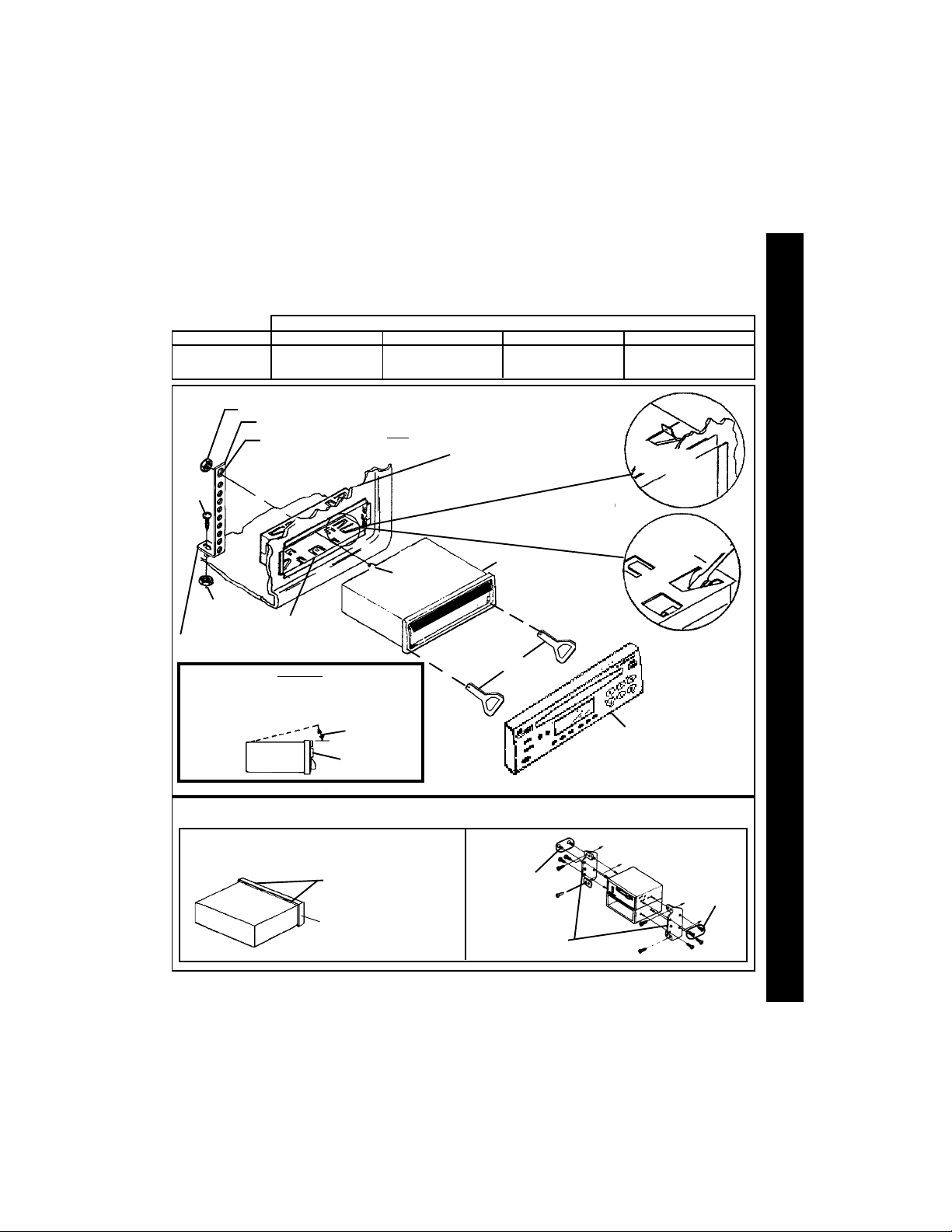
UNIVERSAL INSTALLATION PROCEDURE USING MOUNTING SLEEVE
1. Remove the detachable front panel if it is attached to the chassis by pushing the “Release” button. Slide the
mounting sleeve off of the chassis. If it is locked into position, use the removal tools (supplied) to disengage it.
2. Check the dashboard opening size by sliding the mounting sleeve into it. If the opening is not large enough, carefully
cut or file as necessary until the sleeve easily slides into the opening. Do not force the sleeve into the opening
ION INSTRUCION INSTRUC
ION INSTRUCION INSTRUC
ION INSTRUC
or cause it to bend or bow. Check that there will be sufficient space behind the dashboard for the radio chassis.
TT
TT
T
AA
AA
A
3. Locate the series of bend tabs along the top, bottom, and sides of the mounting sleeve. With the sleeve
fully inserted into the dashboard opening, bend as many of the tabs outward as necessary so that the
sleeve is firmly secured to the dashboard.
ALLALL
ALLALL
ALL
4. Place the radio in front of the dashboard opening so that the wiring can be brought through the mounting
sleeve. Follow the wiring diagram carefully and make certain all connections of the wiring harness are
INSTINST
INSTINST
INST
secure and insulated with wire nuts or electrical tape to insure proper operation of the unit. After completing
the wiring connections, attach the front panel and turn the unit on to confirm operation (ignition switch must
be “on”). If unit does not operate, re-check all wiring until problem is corrected. Once proper operation is
achieved, turn off the ignition switch and proceed with final mounting of the chassis.
5. Carefully slide the radio into the mounting sleeve making sure it is right-side-up until it is fully seated and
the spring clips lock it into place.
6. Attach one end of the perforated support strap (supplied) to the screw stud on the rear of the chassis using
the hex nut provided. Fasten the other end of the perforated strap to a secure part of the dashboard either
above or below the radio using the screw and hex nut provided. Bend the strap to position it as necessary.
CAUTION: The rear of the radio must be supported with the strap to prevent damage to the dashboard from
7. Re-attach the front panel to the chassis and test radio operation by referring to the Operating Instructions for
INSTALLATION USING KITS
1. If your vehicle requires the use of an installation kit to mount this radio, follow the instructions included with
2. Wire and test the radio as described in Step 4 above.
3. Install the radio/mounting plate assembly to the sub-dashboard according to the instructions of the installation kit.
4. Attach the support strap to the radio and dashboard as described in Step 6 above.
5. Replace the dashboard trim panel.
ISO INSTALLATION PROCEDURE
This unit has threaded holes in the chassis side panels which may be used with the original factory mounting
brackets of some Toyota, Nissan, Mitsubishi, Isuzu, Hyundai and Honda vehicles to mount the radio to the
dashboard. Please consult with your local car stereo specialist shop for assistance on this type of installation.
1. Remove the existing factory radio from its dashboard or center console mounting. Save all hardware and
2. Carefully un-snap the plastic frame from the front of the new radio chassis. Remove and discard the frame.
3. Remove the factory mounting brackets and hardware from the existing radio and attach them to the new radio.
CAUTION: DO NOT EXCEED M5 X 8 MM MAXIMUM SCREW SIZE.
22
2
22
4. Wire the new radio to the vehicle as per step 4 above.
5. Mount the new radio assembly to the dashboard or center console using the reverse procedure of step 1.
the weight of the radio or improper operation due to vibration.
theunit.
the installation kit to attach the radio to the mounting plate supplied with the kit.
brackets as they will be used to mount the new radio.
LONGER SCREWS MAY TOUCH AND DAMAGE COMPONENTS INSIDE THE CHASSIS.
Page 3
TOLL-FREE INSTALLATION ASSISTANCETOLL-FREE INSTALLATION ASSISTANCE
TOLL-FREE INSTALLATION ASSISTANCE
TOLL-FREE INSTALLATION ASSISTANCETOLL-FREE INSTALLATION ASSISTANCE
The installation and wiring connections for this unit are so simple, we doubt you'll need our help, but, if you
do, we're here to help you. Just call our toll-free telephone assistance line at 1-800-645-4994 during the days
and hours shown (U.S.A. and Canada only).
DAY
MON. - FRI.
SATURDAY
NUT (5MM)
SCREW
(5MM)
NUT (5MM)
MOUNTING SLEEVE
FASTEN THIS END TO SECURE PART OF
DASHBOARD. DRILL HOLE IF NECESSARY.
FOR PROPER OPERATION OF THE CD PLAYER, THE
CHASSIS MUST BE MOUNTED WITHIN 20° OF
HORIZONTAL. MAKE SURE THE UNIT IS MOUNTED
WITHIN THIS LIMITATION.
SIDE VIEW
OF
CHASSIS
PACIFIC
5:30AM - 4PM
6AM - 2PM
UNIVERSAL INSTALLATION USING MOUNTING SLEEVEUNIVERSAL INSTALLATION USING MOUNTING SLEEVE
UNIVERSAL INSTALLATION USING MOUNTING SLEEVE
UNIVERSAL INSTALLATION USING MOUNTING SLEEVEUNIVERSAL INSTALLATION USING MOUNTING SLEEVE
PERFORATED STRAP
FASTEN THIS END TO
SCREW STUD ON REAR
OF CHASSIS
CAUTION:
EXISTING DASH OPENING
FILE EDGES TO FIT IF NECESSARY - DO NOT OVERFILE
NOTE: IF DASH IS SOLID, USE REAR SIDE (WITHOUT THE
LIP) OF MOUNTING SLEEVE AS A TEMPLATE & CUT
OPENING
20° MAX.
FRONT PANEL
MOUNTAIN
TIME ZONE
6:30AM - 5PM
7AM - 3PM
SCREW STUD
REMOVAL TOOLS
CENTRAL EASTERN
7:30AM - 6PM
8AM - 4PM
RADIO
DETACHABLE
FRONT PANEL
8:30AM - 7PM
9AM - 5PM
BEND TOP
TABS UPWARD
BEND BOTTOM
TABS DOWNWARD
INST
INSTINST
INSTINST
ALL
ALLALL
ALLALL
A
AA
AA
T
TT
TT
ION INSTRUC
ION INSTRUCION INSTRUC
ION INSTRUCION INSTRUC
T
TT
TT
IONS
IONSIONS
IONSIONS
ISO INSTALLATIONISO INSTALLATION
ISO INSTALLATION
ISO INSTALLATIONISO INSTALLATION
REMOVE THE PLASTIC FRAME FROM THE FRONT OF
THE CHASSIS BY CAREFULLY UN-SNAPPING IT.
UN-SNAP AT 2 PLACES
EACH ON TOP AND BOTTOM
PLASTIC FRAME
MAXIMUM
SCREW SIZE
M5 x 8
FACTORY MOUNTING
BRACKETS
TYPICAL INSTALLATION
MAXIMUM
SCREW SIZE
M5 x 8
33
3
33
Page 4

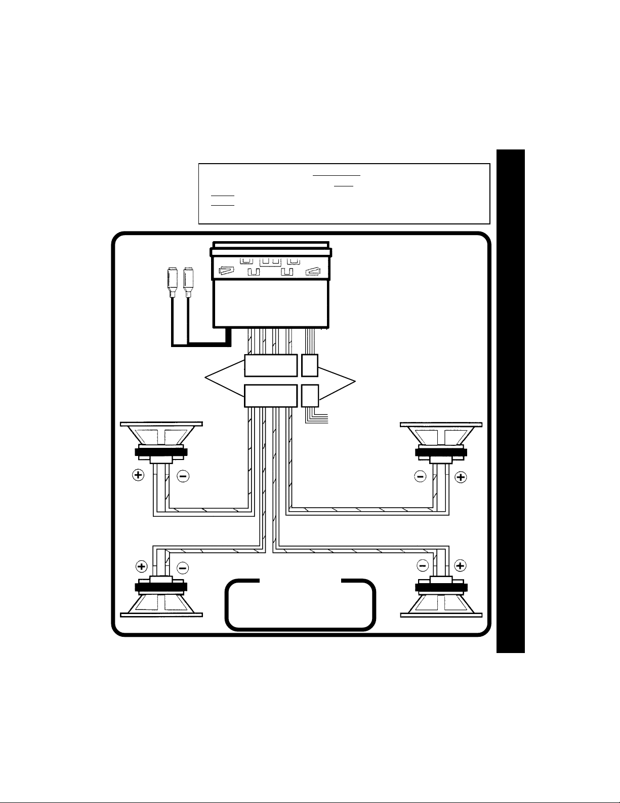
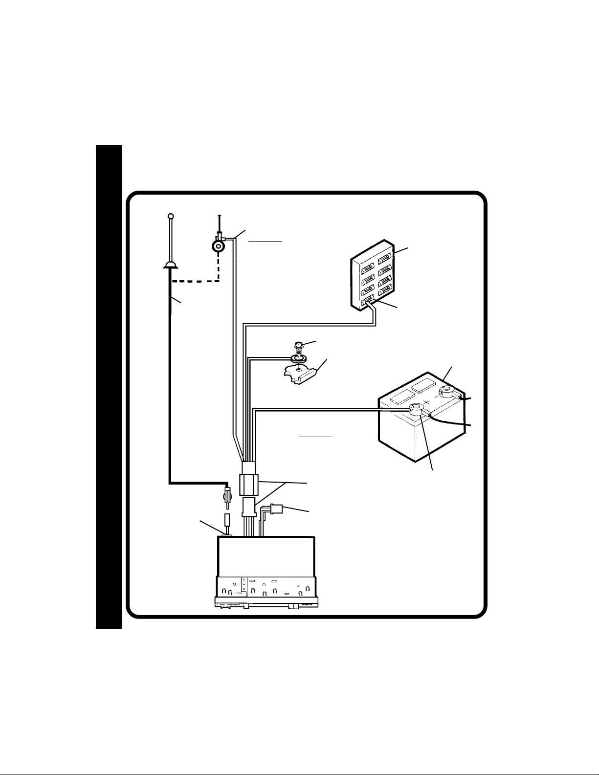
RADIO WIRINGRADIO WIRING
RADIO WIRING
RADIO WIRINGRADIO WIRING
REFER TO PAGE 4 FOR SPEAKER WIRING
ANTENNA
DIO WIRINGDIO WIRING
DIO WIRINGDIO WIRING
DIO WIRING
AA
AA
A
RR
RR
R
EXISTING
ANTENNA
CABLE
AUTOMATIC
ANTENNA
BLUE
IMPORTANT
THE BLUE WIRE CAN BE USED TO
REMOTELY ACTIVATE AN AUTOMATIC
ANTENNA OR AN EXTERNAL AMPLIFIER
(SEE ANTENNA OR AMPLIFIER MANUAL)
RED
SCREW
BLACK
YELLOW WIRE MUST BE CONNECTED
AS SHOWN OR RADIO WILL NOT
OPERATE PROPERLY
IMPORTANT
METAL PART OF DASH
(DRILL HOLE IF NECESSARY)
YELLOW
4-PIN PLUGS
FUSEBLOCK
“RADIO” FUSE
+12V ACCESSORY
CAR BATTERY
POSITIVE (+) TERMINAL
12 VOLT BATTERY
44
4
44
ANTENNA LEAD
ON REAR OF RADIO
9 PIN PLUG
(SEE PAGE 4 FOR SPEAKER WIRING)
Page 5
SPEAKER WIRINGSPEAKER WIRING
SPEAKER WIRING
SPEAKER WIRINGSPEAKER WIRING
REFER TO PAGE 3
FOR RADIO WIRING
RCA JACKS
LINE OUT
FOR USE WITH
OPTIONAL
EXTERNAL
AMPLIFIERS
RED=RIGHT REAR
WHITE=LEFT REAR
WARNING!
l THE AMPLIFIERS IN THIS RADIO ARE ONLY DESIGNED FOR USE WITH 4 SPEAKERS.
l
NEVER COMBINE (BRIDGE) OUTPUTS FOR USE WITH 2 SPEAKERS.
NEVER GROUND NEGATIVE SPEAKER LEADS TO CHASSIS GROUND.
l
l FAILURE TO WIRE EXACTLY AS SHOWN BELOW MAY CAUSE ELECTRICAL
RADIO
SPE
SPESPE
SPESPE
A
AA
AA
K
KK
KK
ER WIRING
ER WIRINGER WIRING
ER WIRINGER WIRING
9-PIN PLUGS
LEFT FRONT SPEAKER
WHITE w/BLACK
STRIPE
WHITE
GREEN
GREEN w/BLACK STRIPE
GRAY w/BLACK STRIPE
VIOLET w/BLACK
4-PIN PLUGS
SEE PAGE 3 FOR
RADIO WIRING
GRAY
VIOLET
RIGHT FRONT SPEAKER
HELP!
1-800-645-49941-800-645-4994
1-800-645-4994
1-800-645-49941-800-645-4994
Monday - Friday
LEFT REAR SPEAKER RIGHT REAR SPEAKER
Saturday
8:30am - 7:00pm Eastern
9:00am - 5:00pm Eastern
55
5
55
Page 6
IONSIONS
IONSIONS
IONS
TT
TT
T
29
30
9
2
20,21
14
12
17
18
26
16
11
ING INSTRUCING INSTRUC
ING INSTRUCING INSTRUC
ING INSTRUC
TT
TT
T
AA
AA
A
28
OPEROPER
OPEROPER
OPER
3, 4, 5, 6, 7
VOL
CONTROL
VOL
AS
PS
SEL
EQ
8,10
LOUD
BAND
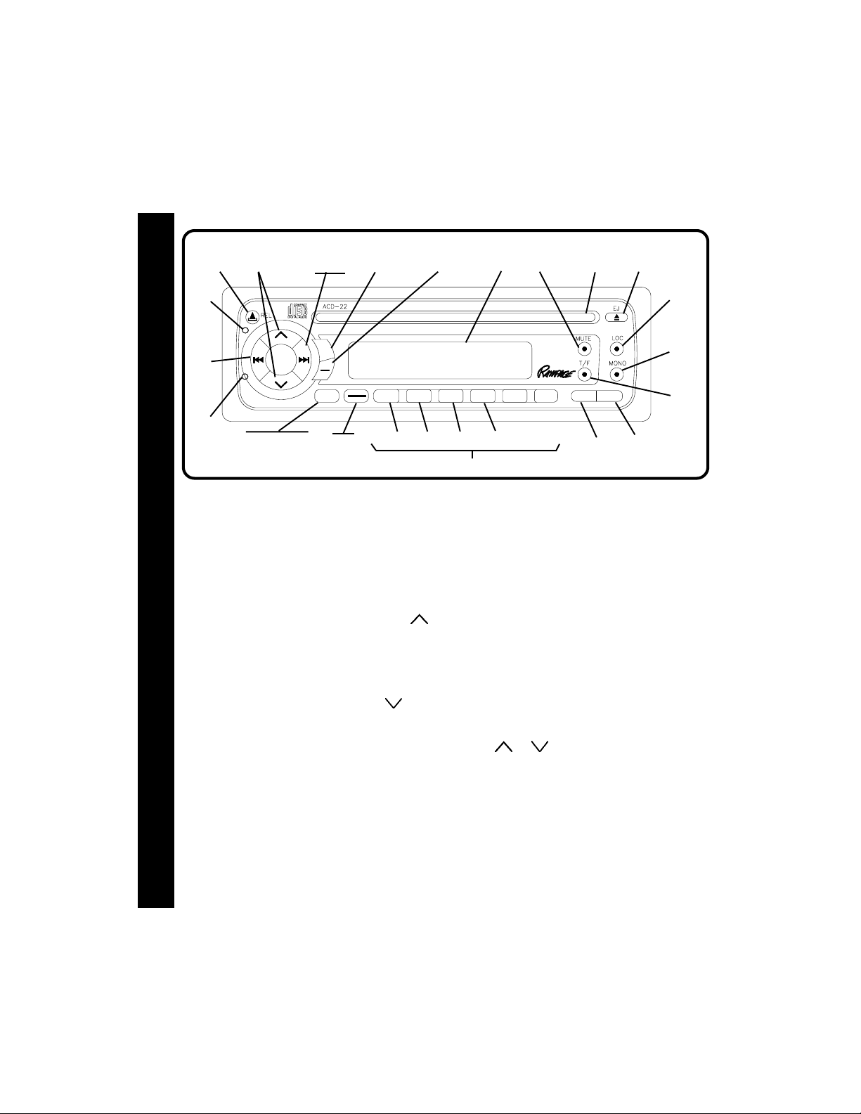
1 POWER ON/OFF BUTTON (PWR)
Press this button to turn the unit on and off.
The unit will also turn on automatically when
a disc is loaded, or when any other button is
pressed.
2 VOLUME / LEVEL CONTROLS
To increase the volume level, press the
button. The volume will increase and the
level will be shown on the display panel
from a minimum of VOL 00 to a maximum
of VOL 100. To increase the volume
quickly, keep the button pressed. To decrease the volume level, press the
ton. Keep the button pressed to decrease
the volume quickly. The display will automatically return to t he n or ma l in d ic a ti o n 5 seconds after the last volume adjustment or
when another function is activated. These
controls are also used in conjunction with
the Select (SEL) button
bass, treble, balance and fader levels as described in
3 SELECT BUTTON (SEL)
66
6
66
This button is used to select the audio
function (volume, bass, treble, balance or
4, 5, 6, and 7.
3 to adjust the
CD-R/RW PLAYBACK
LEVEL METER
1
PAU
2
3
RPT
SCN
22
24 25
23
13
fade) to be adjusted using the Level Control
Pressing the Select button once will set the unit
for volume a d justment (VOL will appear on the
display panel). Pressing the button additional
times will select bass adjustment (BAS on
display panel), treble adjustment (TRB), balance
(BAL), fader (FAD), and volume (VOL) again. The
display will return to the normal indication 5
seconds after the last adjustment or when another function is activated.
4
SHF
56
MODE
PWR
19
15
27
1
2.
4 BASS CONTROL
To adjust the bass level, first select the Bass
but-
mode by pressing the Select button 3 until the
BAS indication appears on the display panel.
Within 5 seconds of choosing the Bass mode,
press the or buttons of the Level Control
2 to adjust the bass response as desired. The
bass level will be shown on the display panel
from a minimum of B--10 to a maximum of B 10
(B 00 represents fl at response). The display
will automatically return to the normal indication 5
seconds after the last adjustment or when
another function is activated. Adjusting the bass
level will automatically return the equalizer setting to the FLAT mode from its previous setting.
Page 7
5 TREBLE CONTROL
To adjust the treble level, first select the Treble
mode by pressing the Select button
the TRB indication appears on the display
panel. Within 5 seconds of choosing the
Treble mode, press the
Level Control
desired. The treble level will be shown on the
display panel from a minimum of TRB--10 to a
maximum of TRB 10 (TRB 00 represents flat response). The display will automatically return
to the normal indication 5 seconds after the
last adjustment or when another function is
activated. Adjusting the treble level will automatically return the equalizer setting to the FLAT mode
from its previous setting.
2 to adjust the treble response as
or buttons of the
3 until
6 LEFT/RIGHT BALANCE CONTROL
To adjust the left-right speaker balance, first select
the Balance mode by pressing the Select button
3 until the BAL indication appears on the display
panel. Within 5 seconds of choosing the Balance
mode, press the button of the Level Control 2
to adjust the st er eo ba lance to the left channel
speakers or the button of the control to adjust
it to the right channel speakers. The balance position
wil l be shown on the display panel from BAL 10L(full
left) to BAL 10R (full right). When the volume level
between the left and right speakers is equal,
BAL L=R will be shown on the display panel. The
display will automatically return to the normal
indication 5 seconds after the last adjustment or
when another function is activated.
7 FRONT/REAR FADER CONTROL
To adjust the front-rear speaker balance, first select the Fader mode by pressing the Select button
3 until the FAD indication appears on the display
panel. Within 5 seconds of choosing the Fader
mode, press the or the buttons of the Level
Control
as desired. The fader position will be shown on
the display panel from FAD 10R(full rear) to
FAD 10F (full front). When the volume level between
the front and rear speakers is equal, FAD F=R will
be shown on the display panel. The display will
automatically return to the normal indication 5 sec-
2 to adjust the front-rear speaker levels
onds after the last adjustment or when another function is activated.
8 LOUDNESS CONTOUR (LOUD)
When listening to music at low volume levels, this feature will boost the bass and treble
ranges to compensate for the characteristics of human hearing. Press and hold the
BAND/LOUD button for 2 seconds to activate this feature as indicated by a beep tone
and LOUD ON appearing on the display
panel for about 5 seconds. (LOUD remains
on the display.) Pressing the button again
for 2 seconds will sound a beep tone and
LOUD OFF will appear on the the display for
about 5 seconds.
9 AUDIO MUTE
This button is used to mute the volume from
the system. By pressing the button, the indication MUTE will appear flashing on the display panel and the volume will be muted.
Pressing the Mute button again or activating
any other function of the unit will return to the
volume level setting in use before the Mute
function was activated.
bl AM/FM BAND SELECTOR
During radio play, each time the button is
pressed, the radio band changes. The indications AM, F1, F2, or F3 will appear on the
display panel according to your selection.
bm MANUAL UP/DOWN ( /
SEEK TUNING
Each time the Up Tuning button (
pressed, the radio will tune higher, seeking
the next strong station and stop. Similarly,
each press of the Down Tuning button
) will tune lower and stop at the next
(
strong station. To manually seek a specific station, press the button in the appropriate direction until the desired frequency
is reached.
Press either button for longer than 2 seconds; MANUAL will appear on the dis-
play. Now, when the Up or Down tuning
)AND
) is
OPER
OPEROPER
OPEROPER
A
AA
AA
T
TT
TT
ING INSTRUC
ING INSTRUCING INSTRUC
ING INSTRUCING INSTRUC
T
TT
TT
IONS
IONSIONS
IONSIONS
77
7
77
66
6
66
Page 8

button is pressed momentarily, tuning will
occur two frequency steps at a time. If either
button is pressed and held in Manual mode
IONSIONS
IONSIONS
IONS
TT
TT
T
for 2 seconds, the manual Seek Tuning function is initiated, whereby the radio will tune
rapidly in the appropriate direction and stop
on, or close to, the desired frequency when
the button is released.
If no further tuning is performed after 5 seconds, AUTO will appear momentarily on the
ING INSTRUCING INSTRUC
ING INSTRUCING INSTRUC
ING INSTRUC
display, and tuning will revert to the original
TT
TT
T
tuning mode.
AA
AA
A
bn AUTO-STORE TUNING (AS)
PRE-SET SCAN TUNING (PS)
OPEROPER
OPEROPER
OPER
Press this button momentarily to scan the 6
stations in the pre-set memories of the FM
band in use, plus the other two FM bands.
The unit will stop at each pre-set station for
10 seconds before continuing to the next
pre-set station (the frequency on the display
panel will flash during Pre-Set Scan operation). Press the button again momentarily
to stop Pre-Set Scan operation and remain
on the selected frequency in that band.
Pressing the button for longer than 2 seconds will activate the Auto-Store Tuning feature. The radio will automatically scan the
band in use and enter strong stations into
the pre-set memory positions for that band.
If you have already set the pre-set memories of that band to your favorite stations,
activating the Auto-Store Tuning feature will
erase those stations and enter the new
strong stations. This feature is most useful
when traveling in a new area where you are
not familiar with the local stations.
bo STA TION PRE-SET MEMORIES
T o set any of the 6 pre-set memory buttons, use
the following procedure:
1.Turn the unit on and select the desired
88
8
88
band.
2.Select the first station to be pre-set using
the Up/Down seek/tuning functions
3.Press the pre-set button to be set and con
tinue tohold the button in. A confirming tone
will be heard and the pre-set number will ap
pear on the display panel. The station is now
set into the memory of that pre-set button and
can be re-called at any time by momentarily
pressing that button.
4.Repeat the above procedure for the remaining
5 pre-sets on the band in use and for the other
3 bands of the unit.
bm.
bp EQUALIZER SELECTOR (EQ)
The EQ button applies preset sound effects to the
unit’s audio output signal. The EQ button, when
pressed, will activate one of the following operating modes: CLASSICS, POP M, ROCK M, FLAT,or
DSP OFF. Nonetheless, when the EQ function is
active, as displayed (
on the panel, the bass and treble levels can still
be changed to accommodate the listener’s ear.
When the EQ function is not active, the unit returns to the user-set bass and treble levels. The
FLAT selection indicates no equalizer enhancement of the program, thereby removing the preset sound effects, unless otherwise desired,
while DSP OFF inhibits selection of equalizer
mode enhancement.
EQ
----CLAS, POP, ROCK)
bq FM MONO/STEREO SELECT (MONO)
During FM radio operation, this button is used to
select monaural or stereo reception of the
broadcast signal. Under normal reception
conditions, the unit should be left in the stereo
mode as indicated by the
panel when tuned to an FM stereo signal. If the
signal is to noisy for comfortable listening, press
the MONO button (the
disappear from the display panel and MONO will
appear).T o return to stereo reception mode, press
the button again so that the
appears on the display panel.
icon on the display
indication will
indication
Page 9
br LOCAL (LOC) BUTTON
This feature is used to select the strength of
the signals at which the radio will stop during
Automatic Seek Tuning. Pressing the button
will select the Local setting (LOCAL will appear
on the display panel for 5 seconds and LOC
will remain in the center of the display) and
only strong (local) stations will be received.
Pressing and holding the button again will
select the Distant setting (Dx will appear on
the display panel for 5 seconds) and the radio
will stop at a wider range of signals, including
weaker (more distant) stations.
bs LIQUID CRYSTAL DISPLA Y P ANEL
The Liquid Crystal Display (LCD) panel displays the
frequency, time, and all activated functions.
NOTE: It is a characteristic of LCD panels that, if
subjected to cold temperatures for an
extended period of time, they may take
longer to illuminate than under normal condi
tions. In addition, the visibility of the numbers
on the LCD may slightly decrease. The LCD
read-out will return to normal when the
temperature increases to a normal range.
bt DISC SLOT
With the label surface facing up, gently insert the
disc into the slot until the soft-loading mechanism
engages and disc play begins. S--CDP will appear
momentarily ; the
mated, and CDP appears together with the track
number and elapsed time.
CAUTION: This unit is designed for play of stan-
dard 5" (12cm) Compact Discs
Do not attempt to use 3" (8cm) CDSingles in this unit, either with or
without an adaptor, as damage to the
player and/or disc can occur. Such
damage will not be covered by the
Warranty on this product.
indication will become ani-
ONLY.
bu MODE SELECTOR (MODE)
This button is used to select the radio, or the playback mode for the CD player. Each press of the
button will select a different mode as indicated on the display panel.
During CD player operation, this button may
be used to change to radio without ejecting the disc (the CDP indication will remain
on the display panel to show that a disc is
still loaded in the unit). Press the button again
to return to integral CD player mode.
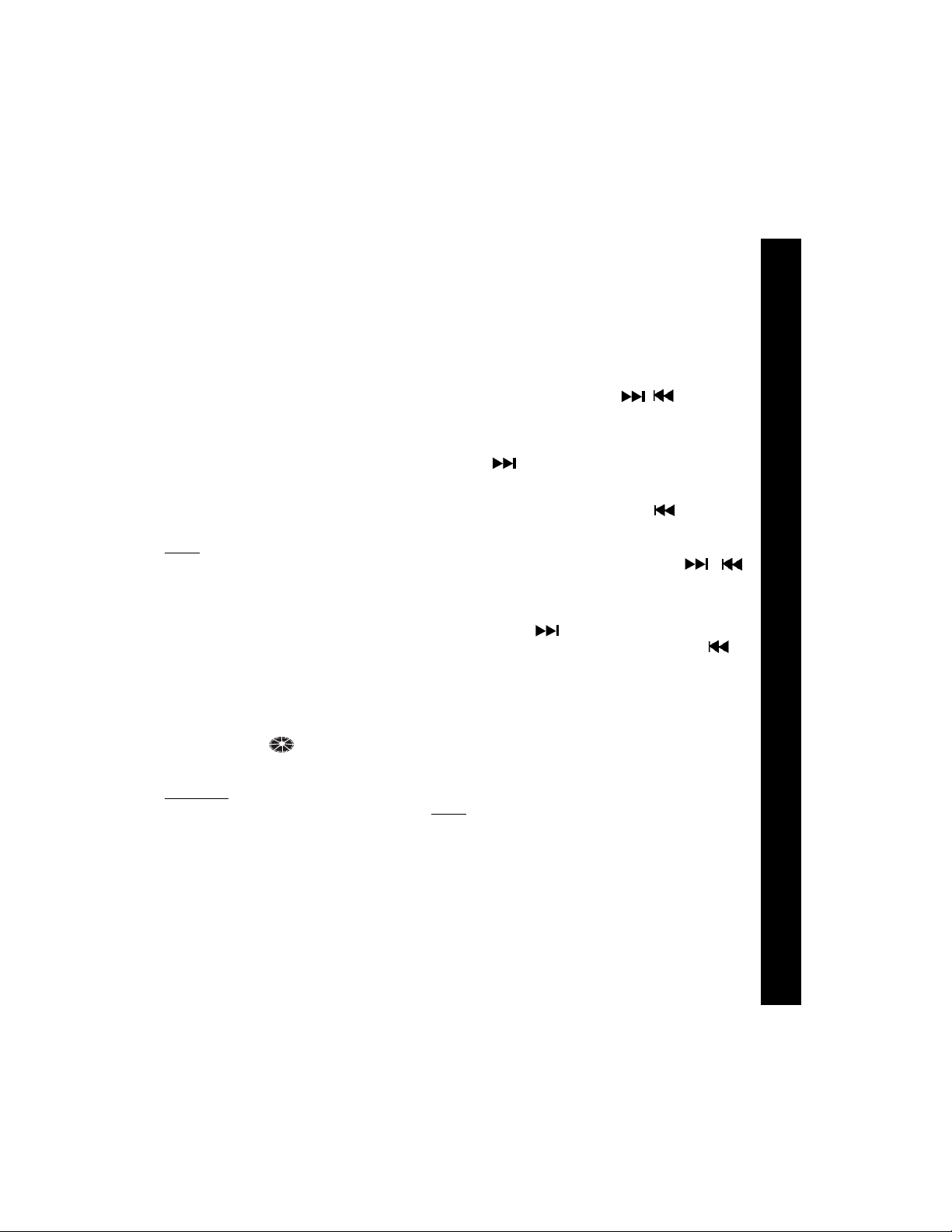
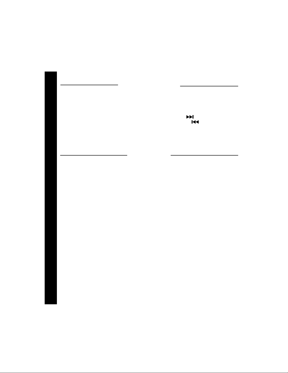
cl TRACK SELECT (
The Track Select functions are used to
quickly access the beginning of a particular
track. Each time the Forward Track Select
(
) button is pressed, the next higher
track number will be selected as shown
on the display panel. Similarly, each time the
Backward Track Select (
pressed, the next lower track number will
be selected as shown on the display panel.
cm CUE/REVIEW FUNCTIONS (
High-speed audible search to any section
of the disc can be made by the Cue and
Review functions. Press and hold the Cue
button (
ward direction or the Review button (
advance rapidly in the backward direction.
During either function, the elapsed time
within each track will automatically be shown
on the display panel.
) to advance rapidly in the for-
/ )
) button is
/ )
) to
cn DISC PAUSE (P AU) SELECT
The Pause function is used to freeze disc
play when the CD player is in use.
S--PAUSE will appear flashing on the display .
Press this button again to resume
the S--PAUSE indication will
disc play;
disappear.
co TRACK SCAN SELECT (SCN)
During disc play, press this button to play the
first 10 seconds of each track on the disc
(S--SCN will appear on the display panel with
the track number). When a desired tr ack is
reached, press the Track Scan button again
to cancel the function and play of the selected track will continue. Track Scan mode
OPER
OPEROPER
OPEROPER
A
AA
AA
T
TT
TT
ING INSTRUC
ING INSTRUCING INSTRUC
ING INSTRUCING INSTRUC
T
TT
TT
IONS
IONSIONS
IONSIONS
99
9
99
Page 10

will also be canceled by activating the Repeat Play
IONSIONS
IONSIONS
IONS
cp TRACK REPEAT PLA Y SELECT (RPT)
TT
TT
T
During disc play, press this button to repeat
the play of the selected track (S--RPT will
appear on the display panel). Play of the
track will continue to repeat until the button
is pressed again and the S--RPT indication disappears from the display panel. Repeat Play mode will also be canceled by acti-
ING INSTRUCING INSTRUC
ING INSTRUCING INSTRUC
ING INSTRUC
vating the Track Scan
TT
TT
T
AA
AA
A
functions.
cp or Shuffle Play cqfunctions.
co or Shuffle Play cq
cq SHUFFLE PLA Y SELECT (SHF)
During disc play, press this button to play the
OPEROPER
OPEROPER
OPER
tracks on the disc in a random shuffled order
(S--SHF will appear on the display panel). In
Shuffle Play mode, pressing the Forward
Track Select (
( ) will also select tracks in a random order
instead of the normal progression.The Shuffle
Play mode can be cancelled by pressing the
button again (S--SHF indication will disappear
from the display panel) or by activating the
Repeat Play cp or Track Scan co functions.
) or Backward Track Select
cr DISC EJECT ( )
When this button is pressed, disc play is
stopped, the disc is ejected and the unit will
change to radio operation (EJECT will briefly
appear on the display panel). If the disc is not
removed from the unit within 15 seconds,
the disc will be re-loaded (S--CDP will reappear).
cs TIME/FREQUENCY(T/F)SELECT
Press this button to call the time display on
the incorporated quartz clock. Press the button again to return to radio frequency or disc
display or it will return automatically after 5
seconds.
ct THEFT-DETERRENT LED
Located on the chassis behind the front
1010
panel, a light-emitting diode (LED) will flash
10
1010
when the panel is removed. The flashing light
serves as a visual warning to the would-be thief
that the unit has been disabled by removal of the
front panel.
cu RESET BUTTON
A RESET button is located on the front of the
chassis above the theft-deterrent LED(front panel
must be removed to access the button). The reset circuitry is provided to protect the microprocessor circuitry and should only be activated under the following circumstances:
1. Upon initial installation after all wiring is
completed.
2. If there is a malfunction of any of the
switches on the unit or of the CD player,
pressing the RESET button may clear the
system and return to normal operation.
dl FRONT PANEL RELEASE BUTT ON ( )
This button is used to release the mechanism
that holds the front panel to the chassis. To detach the front panel, press the button so that the
left side of the panel is released. Grasp the released side and pull it off of the chassis. To reattach the panel, position the right side of the panel
in place first and then press the left side of the
panel until the mechanism locks it into place.
NOTES ON USE OF FRONT PANEL
1. Make sure the front panel is right-side-up when
attaching it to the chassis as it cannot be
attached when up-side down.
2. Do not press very hard on the front panel
when attaching it to the chassis. No
more than light to moderate pressure
should be needed.
3. When attaching the front panel, make
sure the right side is correctly engaged
before pressing the left side to lock it into
position.
4. When taking the front panel with you,
please use the supplied carrying case to
protect the panel from dirt and damage.
Page 11
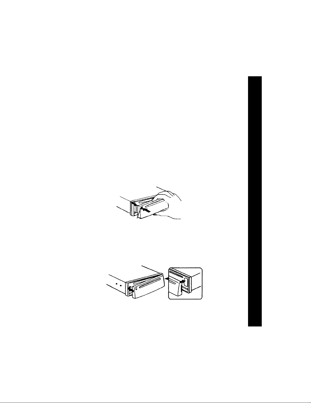
DET ACHING THE FRONT PANEL
Release
button
OPER
OPEROPER
OPEROPER
A
AA
AA
T
TT
TT
ING INSTRUC
ING INSTRUCING INSTRUC
ING INSTRUCING INSTRUC
T
TT
TT
IONS
IONSIONS
IONSIONS
A TTACHING THE FRONT P ANEL
Engage right
side first
1111
11
1111
Page 12
SETSET
TT
ING THE CLOCKING THE CLOCK
SET
T
ING THE CLOCK
SETSET
TT
ING THE CLOCKING THE CLOCK
1. Switch the vehicle ignition “on” and the radio “on” (radio frequency or disc track number will be shown on the display panel).
OR CODESOR CODES
OR CODESOR CODES
OR CODES
2. Momentarily press the Time/Frequency (T/F) button to display the time of day . Then
press and hold the T/F button until the time display flashes.
3. While the display is flashing, press the Up Tuning button (
hours and the A or P indication, and the Down Tuning button (
utes to the correct time.
4. When the correct time is shown on the display panel, press and release the T/F button
(or wait 5 seconds) for the display to return to the normal indication.
ERROR CODESERROR CODES
ERROR CODES
ING THE CLOCK / ERRING THE CLOCK / ERR
ING THE CLOCK / ERRING THE CLOCK / ERR
ING THE CLOCK / ERR
If a problem should develop while operating the CD player, the following error codes
TT
TT
T
may be displayed on the display panel:
SETSET
SETSET
SET
ER-2: Indicates the disc is not loading properly . T ry re-loading or pressing the
Eject button. Check the condition of the disc in use or try another disc.
ER-3: Indicates the disc is not ejecting properly. Try pressing the Eject button
again. Check the condition of the disc in use or try another disc.
ER-4: Indicates an error in the laser reading the disc. Eject the disc, make sure
it is clean, undamaged, and loaded correctly (label side up). Re-load the
disc and check for proper operation or try another disc.
ER-5: Indicates excessive temperature conditions. CD play will resume when
the temperature returns to the normal range.
ER-6: Indicates a mechanism error . Eject the disc and try re-loading. Also try
activating the RESET button cu and try again.
ER-7: Indicates an error in the laser reading the disc. Eject the disc, make sure
it is clean, undamaged, and loaded correctly (label side up). Re-load th e
disc and check for proper operation or try another disc.
ER-8: Indicates an error in the laser reading the disc. Eject the disc, make sure
it is clean, undamaged, and loaded correctly (label side up). Re-load the
disc and check for proper operation or try another disc.
ERROR CODESERROR CODES
) to adjust the
) to adjust the min-
1212
12
1212
If the suggested measures do not solve the problem, contact an approved warranty
station near you for further assistance.
Page 13

SPECIFICATIONSSPECIFICATIONS
SPECIFICATIONS
SPECIFICATIONSSPECIFICATIONS
Size: 7" W x 2" H x 6-1/4" D
178 mm x 50 mm x 160 mm
Operating Voltage: 12 volts DC, negative ground
Output Power: 160 watts maximum
(40 watts x 4 channels)
Output Wiring: Floating-ground type designed for 4 speaker use.
Front and rear channels CANNOT be combined
(bridged) for use with 2 speakers.
RCA low-level outputs (rear channels).
Output Impedance: Compatible with 4-8 ohm speakers.
Low-Level Output: 500 mv.
Tuning Range: AM : 530-1,710 KHz. (10 KHz. step)
FM: 87.5-107.9 MHz. (200 KHz. step)
Sensitivity: AM: 20 uv.
FM: 1.5 uv.
FM Stereo Separation: 30 dB
CD Frequency Response: 20-20,000 Hz. ±1 dB
CD Signal/Noise Ratio: 70 dB
CD Channel Separation: 60 dB
CD Distortion: 0.2%
SPECIFICA
SPECIFICASPECIFICA
SPECIFICASPECIFICA
T
TT
TT
IONS
IONSIONS
IONSIONS
*Specifications are subject to change without notice.
CD-R AND CD-RW PLAYBACK CAPABILITY
This model can play most CD-R and CD-RW media that contains audio programs.
Playback of both CD-R and CD-RW depends on the conditions of the recording equipment
and the CD-R or CD-RW disc quality. In some cases, a CD-R or CD-RW disc cannot be
played on this unit.*Specifications are subject to change without notice.
1313
13
1313
Page 14

CARE AND MAINTENANCECARE AND MAINTENANCE
CARE AND MAINTENANCE
CARE AND MAINTENANCECARE AND MAINTENANCE
The radio section of your new sound system does not require any maintenance. We
NCENCE
NCENCE
NCE
recommend that you keep this manual for reference on the many features found in this unit as
well as how to set the clock.
The compact disc player section also requires no routine maintenance, but proper
understanding of its use and handling will help you obtain maximum enjoyment of its
INTENAINTENA
INTENAINTENA
INTENA
capabilities. The following points should be observed:
l When cleaning the interior of the vehicle, do not get water or cleaning fluids on the unit.
l The CD player is a precision instrument and will not operate properly in extreme heat or cold.
ND MAND MA
ND MAND MA
ND MA
In case of such conditions, wait until the interior temperature of the vehicle reaches a normal
temperature before using the player.
RE ARE A
RE ARE A
RE A
l If the temperature inside the player gets too hot, a protective circuit will automatically stop
play of the disc. In this case, allow the unit to cool off before operating the player again.
CACA
CACA
CA
l Never insert anything other than a 5" (12 cm) compact disc into the player as the
mechanism can be damaged by foreign objects.
l Do not attempt to use 3" (8 cm) CD-Single discs in this unit, either with or without an
adaptor, as damage to the player and/or disc may occur. Such damage will not be covered
by the Warranty on this product.
l When not using the disc player, always remove the compact disc. Do not leave an ejected
disc sitting in the disc slot as this can expose it to sunlight and other causes of damage.
l Do not attempt to open the unit chassis. There are no user serviceable parts or adjustments
inside.
l When the vehicle warms up during cold weather or under damp conditions, moisture may
condense on the lens of the disc player. Should this occur, the player will not operate
properly until the moisture has evaporated.
l The unit is designed with a vibration dampening CD mechanism to minimize interruption
of disc play due to normal vibration in a moving vehicle. When driving on very rough roads,
however, occasional sound skips may occur. This will not scratch or damage the disc and
normal play will resume when the rough conditions cease.
HANDLING COMPACT DISCS
Dirt, dust, scratches, and warpage can cause skips in the playback and deterioration of sound
quality. Please follow these guidelines to take care of your compact discs:
1414
14
1414
l Use only compact discs with the mark .
l Fingerprints, dust, and dirt should be carefully wiped off the disc’s playing surface (shiny
side)with a soft cloth. Wipe in a straight motion from the inside to the outside of the disc.
l Never use chemicals such as record sprays, household cleaners or thinner to clean
compact discs. Such chemicals can irreparably damage the disc’s surface.
l Discs should be kept in their storage cases when not in use.
l Do not expose discs to direct sunlight, high temperatures or high humidity for extended
periods.
l Do not stick paper, tape, or labels on the disc surfaces nor write on them with any type of
marker.
Page 15

WARRANTY
WARRANTYWARRANTY
WARRANTYWARRANTY
12 MONTH LIMI12 MONTH LIMI
12 MONTH LIMI
12 MONTH LIMI12 MONTH LIMI
AUDIOVOX CORPORATION (the Company) warrants to the original retail purchaser
of this product that should this product or any part thereof, under normal use and
conditions, be proven defective in material or workmanship within 12 months from the
date of original purchase, such defect(s) will be repaired or replaced with new or
reconditioned product (at the Company's option) without charge for parts and repair
labor.
To obtain repair or replacement within the terms of this Warranty, the product is to be
delivered with proof of warranty coverage (e.g. dated bill of sale), specification of defect(s),
transportation prepaid, to the warranty center at the address shown below.
This Warranty does not extend to the elimination of car static or motor noise, to
correction of antenna problems, to costs incurred for installation, removal, or reinstallation of the product, or damage to tapes, compact discs, speakers, accessories, or
vehicle electrical systems.
This Warranty does not apply to any product or part thereof which, in the opinion of the
Company, has suffered or been damaged through alteration, improper installation,
mishandling, misuse, neglect, accident, or by removal or defacement of the factory
serial number/bar code label(s). THE EXTENT OF THE COMPANY'S LIABILITY
UNDER THIS WARRANTY IS LIMITED TO THE REPAIR OR REPLACEMENT
PROVIDED ABOVE AND, IN NO EVENT, SHALL THE COMPANY'S LIABILITY
EXCEED THE PURCHASE PRICE PAID BY PURCHASER FOR THE PRODUCT.
This Warranty is in lieu of all other express warranties or liabilities. ANY IMPLIED
WARRANTIES, INCLUDING ANY IMPLIED WARRANTY OF MERCHANTABILITY,
SHALL BE LIMITED TO THE DURATION OF THIS WRITTEN WARRANTY. ANY
ACTION FOR BREACH OF ANY WARRANTY HEREUNDER INCLUDING ANY IMPLIED
WARRANTY OF MERCHANTABILITY MUST BE BROUGHT WITHIN A PERIOD OF 30
MONTHS FROM DATE OF ORIGINAL PURCHASE. IN NO CASE SHALL THE
COMPANY BE LIABLE FOR ANY CONSEQUENTIAL OR INCIDENTAL DAMAGES
FOR BREACH OF THIS OR ANY OTHER WARRANTY, EXPRESS OR IMPLIED,
WHATSOEVER. No person or representative is authorized to assume for the
Company any liability other than expressed herein in connection with the sale of this
product.
Some states do not allow limitations on how long an implied warranty lasts or the
exclusion or limitation of incidental or consequential damage so the above limitations
or exclusions may not apply to you. This Warranty gives you specific legal rights and
you may also have other rights which vary from state to state.
TED WTED W
TED W
TED WTED W
AA
RRRR
AA
NTNT
A
RR
AA
RRRR
YY
A
NT
Y
AA
NTNT
YY
U.S.A.: AUDIOVOX CORPORATION, 150 MARCUS BLVD., HAUPPAUGE, NEW YORK 11788 • 1-800-645-4994
CANADA: CALL 1-800-645-4994 FOR LOCATION OF WARRANTY STATION SERVING YOUR AREA
Form No. 128-4270E
1515
15
1515
Page 16

DIRECTIVES D’INSTALLATIONDIRECTIVES D’INSTALLATION
DIRECTIVES D’INSTALLATION
Cet appareil est conçu pour être installé dans une voiture, un camion ou une fourgonnette étant déjà doté
d’une ouverture pour la radio. Dans bien des cas, il faudra un nécessaire spécial d’installation pour
monter la radio au tableau de bord. Ces nécessaires sont vendus dans les magasins de matériel
électronique et les ateliers spécialisés dans l’installation des chaînes stéréo d’auto. Vérifiez toujours
l’utilisation indiquée du nécessaire avant de l’acheter pour vous assurer qu’il convient à votre véhicule.
S’il vous faut un nécessaire mais que vous ne parvenez pas à vous en procurez un, composez le
numéro de notre ligne d’assistance sans frais.
INSTALLA TION UNIVERSELLE
1. Retirer le panneau avant, s’il est fixé au châssis, en poussant le bouton de libération “Release”. Faire glisser
la gaine de montage hors du châssis. Si elle est bloquée, la dégager à l’aide des outils de retrait (fourni).
2. Vérifier la taille de l’ouverture pratiquée dans le tableau de bord en y insérant la gaine. Si l’ouverture n’est
pas suffisante, découper ou limer délicatement les bords jusqu’à ce que la gaine puisse être insérée
aisément dans l’ouverture. Ne pas forcer la gaine dans l’ouverture et éviter de la courber ou de la plier.
Vérifier qu’il y ait suffisamment d’espace derrière le tableau de bord pour loger le châssis de la radio.
3. Repérer la série de pattes de pliage situées sur le pourtour de la gaine de montage. Cette dernière étant
complètement introduite dans l’ouverture du tableau de bord, replier vers l’extérieur autant de pattes qu’il
est nécessaire pour fixer solidement la gaine au tableau de bord.
4. Placer la radio devant l’ouverture du tableau de bord de manière à ce que le câblage puisse être acheminé
à travers la gaine. Suivre rigoureusement le schéma de câblage et s’assurer que tous les branchements
DIRECTIVES D'INSTALLATIONDIRECTIVES D'INSTALLATION
DIRECTIVES D'INSTALLATIONDIRECTIVES D'INSTALLATION
DIRECTIVES D'INSTALLATION
du harnais de câbles sont solides et isolés avec des écrous ou du ruban isolant pour garantir un
fonctionnement correct de l’unité. Une fois le câblage terminé, fixer le panneau avant et mettre l’unité sous
tension pour vérifier le bon fonctionnement (la clé de contact doit être tournée). Si l’unité ne se met pas
en marche, vérifier tous les câblages jusqu’à ce que le problème disparaisse. Une fois l’installation réussie,
couper le contact, et procéder au montage final de ce dernier.
5. Insérer délicatement la radio dans la gaine de montage, en s’assurant que la radio ne soit pas sens dessus
dessous, jusqu’à ce qu’elle repose complètement et que les pinces à ressort s’enclenchent.
6. Fixer l’une des extrémités de l’étrier perforé (fourni) au crampon à vis situé à l’arrière de la radio, à l’aide
de l’écrou hexagonal fourni. Fixer l’autre extrémité de l’étrier à une partie fixe du tableau de bord, soit
endessus, soit en-dessous de la radio, à l’aide de la vis et de l’écrou hexagonal fournis. Courber l’étrier
pour rectifier la position si nécessaire.
1616
16
1616
ATTENTION: L’arrière de la radio doit être soutenu par l’étrier pour éviter que le poids de l’unité ou un
7. Remonter le panneau avant sur le châssis et vérifier le fonctionnement de la radio en se reportant aux
consignes de fonctionnement de l’unité.
RETIRER L'AUTORADIO DES INST ALLA TIONS DE LA GAINE DE MONTAGE
1. S'il s'avère nécessaire d'enlever l'autoradio pour le réparer ou pour toute autre raison, retirez d'abord
le panneau avant amovible.
2. Retirez l'armature de support arrière en dévissant l'écrou hexagonal la maintenant au goujon prisonnier
àl'arrière du châssis.
3. Utilisez les outils de retrait (fournis) afin de dégager les agrafes à ressort latérales et extgraire l'autoradio
de la gaine de montage.
METHODE DE POSE ISO
Les panneaux latéraux du boîtier de cet appareil sont dotés de trous filetés pouvant être utilisés avec les
supports de montage d’origine de certains véhicules Toyota, Nissan, Mitsubishi, Isuzu, Hyundai et Honda
pour monter l’autoradio sur tableau de bord. Veuillez demander avis à votre magasin d’autoradios local
pour vous qu’il vousconseille sur ce type de pose.
1. Enlevez l’autoradio d’origine du tableau de bord ou de sa console centrale. Conservez tout le matériel et
les fixations car vous en aurez besoin pour monter le nouvel autoradio.
2. Détacher délicatement le cadre de plastique du devant du châssis de la nouvelle radio, puis l 'enlever et la jeter.
3. Retirez les supports de montage et le matériel de l’autoradio d’origine et fixez-les sur le nouvel autoradio.
ATTENTION :N’UTILISEZ PAS DE VIS D’UNE TAILLE SUPERIEURE A M5X8MM. DES VIS D’UNE LONGUEUR
4. Branchez le nouvel autoradio sur le véhicule en suivant l’étape 4 ci-dessus.
5. Montez le nouveau bloc autoradio sur le tableau de bord ou sur la console centrale en suivant l’étape 1
en sens inverse.
fonctionnement incorrect dû aux vibrations n’endommagent le tableau de bord.
SUPERIEURE POURRAIENT TOUCHER ET ENDOMMAGER LES ELEMENTS SE TROUVANT A
L’INTERIEUR DU CHASSIS.
DIRECTIVES D’INSTALLATIONDIRECTIVES D’INSTALLATION
Page 17

ASSISTANCE GRATUITEASSISTANCE GRATUITE
ASSISTANCE GRATUITE
ASSISTANCE GRATUITEASSISTANCE GRATUITE
Le montage et les branchements sont si simples que vous n'aurez vraisemblablement besoin d'aucune
assistance; toutefois, nous sommes là pour vous aider en cas de besoin. Il suffit d'appeler notre ligne
d'assistance (appel gratuit) 1-800-645-4994 (aux Etats-Unis et Canada).
CÓTE QUEST
LUNDI AU VENDREDI
SAMEDI
ECROU
ETRIER PERFORE
ATTACHER CETTE EXTREMITE
AU CRAMPON A VIS A
L’ARRIERE DU CHASSIS
VIS
ECROU
GAINE DE MONTAGE
ATTACHER CETTE EXTREMITE POUR FIXER LA PIECE AU
TABLEAU DE BORD. PERCER UN TROU SI NECESSAIRE.
POUR QUE LE LECTEUR DE CD FONTIONNE CORRECTEMENT LE
CHÂSSIS DOIT ÊTRE MONTÉ SELON UN ANGLE INFÉRIEUR À 20°
DE LA POSITION HORIZONTAL EL ASSUREZ-VOUZ QUE
L'APPAREIL EST MONTÉ EN FONCTION DE CETTE RESTRICTION.
VUE LATÉRALE
DU CHÂSSIS
ATTENTION
5:30AM - 4PM
6AM - 2PM
INSTALLATION UNIVERSELLE
20° MAXIMUM
PANNEAU AVANT
MONTAGNE
6:30AM - 5PM
7AM - 3PM
OUVERTURE ACTUELLE DANS LE TABLEAU DE BORD (LIMER
LES BORDS POUR ACCOMODER L’UNITE SI NECESSAIRE - NE
PAS LIMER TROP LOIN)
REMARQUE : SI LE TABLEAU DE BORD EST PLEIN, UTILISER LA
GAINE DE MONTAGE COMME GABARIT ET DECOUPER
L’OUVERTURE
CRAMPON A VIS
HORAIRES
RADIO
OUTILS DE RETRAIT
CENTRE CÔTE EST
7:30AM - 6PM
8AM - 4PM
PANNEAU AVANT
AMOVIBLE
8:30AM - 7PM
9AM - 5PM
REPLIER LES PATTES
SUPERIEURES VERS
LE HAUT
REPLIER LES
PATTESINFERIEURES
VERS LE BAS
INST
INSTINST
INSTINST
ALL
ALLALL
ALLALL
A
AA
AA
T
TT
TT
ION UNI
ION UNIION UNI
ION UNIION UNI
VERSELLE
VERSELLEVERSELLE
VERSELLEVERSELLE
ENLEVER LE CADRE DE PLASTIQUE DU DEVANT DU
CHÂSSIS EN LE DÉTACHANT DÉLICATEMENT.
DÉTACHER À DEUX ENDROITS
SUR LE DESSUS ET À DEUS
ENDROITS EN DESSOUS.
CADRE DE
PLASTIQUE
INSTALLATION ISOINSTALLATION ISO
INSTALLATION ISO
INSTALLATION ISOINSTALLATION ISO
DIMENSION
MAX.
M5 x 8
SUPPORTS DE
MONTAGE D'ORIGINE
INSTALLATION (TYPIQUE)
DIMENSION
MAX.
M5 x 8
1717
17
1717
Page 18
SCHEMA DE CABLSCHEMA DE CABL
SCHEMA DE CABL
SCHEMA DE CABLSCHEMA DE CABL
GEGE
GEGE
GE
AA
AA
A
AA
GEGE
A
GE
AA
GEGE
ANTENNE
SCHEMA DE CABLSCHEMA DE CABL
SCHEMA DE CABLSCHEMA DE CABL
SCHEMA DE CABL
ANTENNE A COMMANDE
LE FIL
D'ANTENNE
ELECTRIQUE
BLEU
IMPORTANT
DU FIL BLEU PEUT ETRE UTILISE POUR
ACTIVER A DISTANCE UNE ANTENNE A
COMMANDE ELECTRIQUE AUTOMATIQUE
OU POUR ALLUMER UN AMPLIFICATEUR
EXTERIEUR OPTIONNEL. REPORTEZ-VOUS
A LA NOTICE DÍNSTALLATION DE
L'ANTENNE OU DE L'AMPLIFICATEUR.
ROUGE
VIS
NOIR
IMPORTANT
BRANCHER LE FIL JAUNE VERS LA
SOURCE +12 VOLTS CONSTANTE.
ATTACHE EXISTANTE DANS LE
TABLEAU DE BORD
(PERCER SI NÉCESSAIRE)
JAUNE
FICHE À 4 BROCHES
COFRET À FUSIBLES
FUSIBLE "RADIO"
OU "ACCESSORY"
CAR BATTERY
BORNE POSITIVE DE LA
BATTERIE (12 VOLT)
1818
18
1818
PRISE D'ANTENNE AU
DOS DE LA RADIO
POSTE DE RADIO
FICHE À 9 BROCHES
RACCORDER TOUS LES AUTRES FILS COMME
IL EST MONTRE À LA PAGE 18.
Page 19

SYSTEME DES HAUT-PARLEURS
l LES AMPLIFICATEURS DE CET AUTORADIO SONT UNIQUEMENT CONÇCUS POUR UNE UTILISATION AVEC 4 HAUT-PARLEURS.
l NE COMBINEZ JAMAIS (PAR UN MONTAGE EN PONT) DES SORTIES POUR UNE UTILISATION AVEC 2 HAUT-PARLEURS.
l NE METTEZ
l TOUT MAUVAIS CABLAGE PEUT ENDOMMAGER L'AUTORADIO.
SORTIES RCA BASSE
PUISSANCE
A CONNECTER
A UN/DES
AMPLIFICATEUR(S)
EXTERIEUR(S)
OPTIONNELS
ROUGE=CANAL DROIT
ARRIÈRE
BLANC=CANAL
GAUCHE ARRIÈRE
JAMAIS A LA MASSE DES CABLES DES HAUT-PARLEURS NEGATIFS.
POSTE DE RADIO
ATTENTION!
SY
SYSY
SYSY
STEME DES H
STEME DES HSTEME DES H
STEME DES HSTEME DES H
AUT-P
AUT-PAUT-P
AUT-PAUT-P
A
AA
AA
RLEURS
RLEURSRLEURS
RLEURSRLEURS
FICHE À 9 BROCHES
HAUT-PARLEUR AVANT GAUCHE HAUT-PARLEUR AVANT DROIT
BLANC RAYE NOIR
BLANC
VERT
VERT RAYE NOIR
GRIS RAYE NOIR
FICHE À 4 BROCHES
RACCORDER TOUS
LES AUTRES FILS
COMME IL EST MONTRE
À LA PAGE 17.
GRIS
VIOLET
VIOLET RAYE NOIR
HELP!
1-800-645-49941-800-645-4994
1-800-645-4994
1-800-645-49941-800-645-4994
8:30am - 7:00pm Côte Est
9:00am - 5:00pm Côte Est
HAUT-PARLEUR ARRIÈRE DROIT
HAUT-PARLEUR ARRIÈRE GAUCHE
Lundi au Vendredi
Samedi
1919
19
1919
Page 20

IONION
IONION
ION
TT
TT
T
30
2
20,21
14
12
17
9
18
26
ILISAILISA
ILISAILISA
ILISA
ICE D’UTICE D’UT
ICE D’UTICE D’UT
ICE D’UT
TT
TT
T
NONO
NONO
NO
2020
20
2020
29
11
28
VOL
CONTROL
VOL
3, 4, 5, 6, 7
AS
PS
SEL
EQ
8,10
LOUD
BAND
1
PAU
2
22
1 TOUCHE DE MARCHE-ARRÊT (PWR)
Appuyez sur cette touche pour allumer ou
éteindre l’appareil. L’appareil s’allume
automatiquement lors du chargement d’un
disque compact ou lorsque l’on appuie sur
n’importe quelle autre touche.
2 TOUCHES DE RÉGLAGE DU VOLUME /
NIVEAU
Pour augmenter le volume, appuyez sur la
touche . Le volume augmentera et le
niveau s’inscrira sur l’afficheur, sa valeur
étant comprise entre VOL 00 et VOL 100.
Pour augmenter rapidement le volume,
maintenez la touche enfoncée. Pour
baisser le volume, appuyez sur la touche
. Maintenez la touche enfoncée pour
baisser le volume rapidement. L’affichage
revient automatiquement à l’indication
normale 5 secondes après le dernier
réglage du volume ou lorsqu’une autre
fonction est activée. Les touches de
réglage permettent également, en
conjonction avec le sélecteur (SEL) 3, de
régler le niveau des basses, des aigus, de
la balance et de l’équilibreur avant-arrière,
comme le décrivent les sections
et 7.
4,5,6
CD-R/RW PLAYBACK
SCN
23
3
RPT
24 25
13
4
SHF
LEVEL METER
56
MODE
19
PWR
1
3 SÉLECTEUR (SEL)
Cette touche permet de sélectionner la fonction
audio (volume, basses, aigus, balance ou
équilibreur avant-arrière) à régler à l’aide de
la touche de réglage du niveau 2. Une pression
unique sur le sélecteur permet d’accéder au
réglage du volume de l’appareil (VOL s’inscrit
sur l’afficheur). Les pressions suivantes
permettent de sélectionner le réglage des
basses (BAS s’affiche), le réglage des aigus
(TRB), de la balance (BAL) ou de l’équilibreur
avant-arrière (FAD), puis de nouveau du volume (VOL). L’affichage revient
automatiquement à l’indication normale 5
secondes après le dernier réglage ou
lorsqu’une autre fonction est activée.
4 RÉGLAGE DES BASSES
Pour régler le niveau des basses, commencez
par sélectionner le mode Basses en appuyant
sur le sélecteur 3 jusqu’à ce que l’indication
BAS s’affiche. Dans un délai de 5 secondes
après avoir choisi le mode Basses, appuyez
sur la touche
pour régler les basses au niveau voulu. Le
niveau s’affichera et sera compris entre B-10
et B 10 (B 00 représentant la fidélité uniforme).
ou de réglage du niveau 2
16
15
27
Page 21

L’affichage reviendra automatiquement à
l’indication normale 5 secondes après le dernier
réglage ou lorsqu’une autre fonction sera
activée. Régler le niveau des basses fait
automatiquement revenir l’égaliseur en mode
FLAT (fidélité uniforme) et annule le réglage
antérieur.
5 RÉGLAGE DES AIGUS
Pour régler le niveau des aigus, commencez
par sélectionner le mode Aigus en appuyant
sur le sélecteur 3 jusqu’à ce que l’indication
TRB s’affiche. Dans un délai de 5 secondes
après avoir choisi le mode Aigus, appuyez sur
la touche
régler les aigus au niveau voulu. Le niveau
s’affichera et sera compris entre TRB—10 et
TRB 10 (TRB 00 représentant la fidélité
uniforme). L’affichage reviendra
automatiquement à l’indication normale 5
secondes après le dernier réglage ou
lorsqu’une autre fonction sera activée. Régler
le niveau des aigus fait automatiquement
revenir l’égaliseur en mode FLAT (fidélité
uniforme) et annule le réglage antérieur.
ou de réglage du niveau 2 pour
6 RÉGLAGE DE LA BALANCE DROITE/GAUCHE
Pour régler la balance entre le haut-parleur droit
et le haut-parleur gauche, commencez par
sélectionner le mode Balance en appuyant sur
le sélecteur 3 jusqu’à ce que l’indication BAL
s’affiche. Dans un délai de 5 secondes après
avoir choisi le mode Balance, appuyez sur la
touche
privilégier les haut-parleurs de la voie gauche,
ou sur la touche de réglage pour privilégier
les haut-parleurs de la voie droite. Le niveau de
la balance s’affichera et sera compris entre BAL
10L (haut-parleurs droits coupés) et BAL 10R
(haut-parleurs gauches coupés). Lorsque le
volume entre les haut-parleurs droit et gauche
est équilibré, l’afficheur indique BAL L=R.
L’affichage revient automatiquement à
l’indication normale 5 secondes après le dernier
réglage ou lorsqu’une autre fonction est activée.
de réglage du niveau 2 pour
7 RÉGLAGE DE L ’ÉQUILIBREUR A VANT/
ARRIÈRE
Pour réaliser l’équilibrage entre les hautparleurs avant et arrière, commencez par
sélectionner le mode Équilibreur avantarrière en appuyant sur le sélecteur 3
jusqu’à ce que l’indication FAD s’affiche.
Dans un délai de 5 secondes après avoir
choisi le mode Équilibreur avant-arrière,
appuyez sur la touche
du niveau 2 pour réaliser l’équilibrage entre
les haut-parleurs avant et arrière de la
manière voulue. Le niveau de l’équilibreur
avant-arrière s’affichera et sera compris
entre FAD 10R (haut-parleurs avant coupés)
et FAD 10F (haut-parleurs arrière coupés).
Lorsque le niveau des haut-parleurs avant
et arrière est équilibré, l’afficheur indique
FAD F=R. L’affichage revient automatiquement à l’indication normale 5 secondes
après le dernier réglage ou lorsqu’une autre fonction est activée.
ou de réglage
8 COMPENSATION PHYSIOLOGIQUE
(LOUD)
Lorsque vous écoutez de la musique à
faible volume, cette fonction accentue les
fréquences basses et aiguës de façon à
compenser les insuffisances de l’oreille
humaine. Pressez la touche BAND/LOUD
et maintenez-la enfoncée pendant 2
secondes pour activer cette fonction.
L’activation est confirmée par un signal
sonore et par l’affichage de LOUD ON pendant 5 secondes environ. (LOUD reste
affiché). Une nouvelle pression de 2
secondes sur la touche fait retentir un signal sonore et LOUD OFF s’affiche pendant 5
secondes environ.
9 MISE EN SOURDINE
Cette touche permet de couper le son de la
chaîne stéréo. Une pression sur la touche
fait apparaître l’indication MUTE qui clignote
sur l’afficheur et coupe le volume. Appuyer
NO
NONO
NONO
T
TT
TT
ICE D’UT
ICE D’UTICE D’UT
ICE D’UTICE D’UT
ILISA
ILISAILISA
ILISAILISA
T
TT
TT
ION
IONION
IONION
2121
21
2121
2121
21
2121
Page 22

de nouveau sur la touche de mise en
sourdine ou activer toute autre fonction fait
IONION
IONION
ION
TT
TT
revenir l’appareil au niveau sonore antérieur.
T
bl SÉLECTEUR DE BANDE AM/FM
En mode radio, chaque brève pression sur
ILISAILISA
ILISAILISA
ILISA
cette touche change de bande radio.
L’indication AM, F1, F2 ou F3 s’inscrira sur
l’afficheur en fonction de votre sélection.
bm SYNTONISA TION MANUELLE VERS LE
ICE D’UTICE D’UT
ICE D’UTICE D’UT
ICE D’UT
HAUT OU VERS LE BAS (
TT
TT
T
SYNTONISATION AUTOMATIQUE PAR
NONO
NONO
NO
REPÉRAGE
Chaque fois que l’on appuie sur la touche
de syntonisation vers le haut (
l’autoradio se syntonise dans le sens des
fréquences plus élevées, repère la station
suffisamment puissante suivante et s’y
arrête. De la même façon, chaque pression
sur la touche de syntonisation vers le bas
) syntonise l’appareil dans le sens
(
des fréquences plus basses et s’arrête sur
la station suffisamment puissante suivante.
Pour faire l’accord sur une station
manuellement, appuyez sur la touche
correspondant à la direction choisie jusqu’à
ce que vous parveniez à la fréquence
désirée. Appuyez sur l’une des deux touches
pendant plus de 2 secondes; MANUAL
s’affiche. À présent, lorsque l’on appuie
brièvement sur la touche de syntonisation
vers le haut ou vers le bas, la syntonisation
s’effectue par bloc de deux pas de
fréquences. En mode manuel, une pression
supérieure à 2 secondes sur l’une des deux
touches a pour effet de lancer la
syntonisation manuelle rapide de
l’autoradio dans la direction choisie jusqu’à
ce que l’on relâche la touche; l’appareil
s’arrête alors sur ou à proximité de la
fréquence désirée.
Si la syntonisation est interrompue pendant
plus de 5 secondes, AUTO s’affiche
2222
22
brièvement et l’on revient au mode de
2222
syntonisation d’origine.
/
bn MÉMORISATION AUTOMA TIQUE DES ST A-
TIONS (AS) SYNTONISATION DES
PRÉSÉLECTIONS PAR BALA Y AGE (PS)
Appuyez brièvement sur cette touche pour
balayer les 6 stations présélectionnées de la
bande FM utilisée ainsi que des deux autres
bandes FM. L’appareil s’arrête 10 secondes
sur chaque station présélectionnée avant de
passer à la suivante (la fréquence clignote sur
l’afficheur durant le balayage des
présélections). Appuyez de nouveau
)
brièvement sur la touche pour interrompre la
fonction de syntonisation des présélections
par balayage et rester sur la fréquence choisie
de la bande utilisée.
),
Une pression supérieure à 2 secondes sur la
touche active la fonction de mémorisation
automatique des stations. L’autoradio balaie
automatiquement la bande utilisée et
mémorise les stations suffisamment
puissantes dans les emplacements mémoire
de cette bande. Si vous avez déjà attribué les
emplacements mémoire à vos stations favorites, activer la fonction de mémorisation
automatique des stations effacera ces
dernières pour mémoriser à leur place de
nouvelles stations suffisamment puissantes.
Cette fonction est particulièrement utile
lorsque vous voyagez dans une région dont
vous ne connaissez pas les stations locales.
bo PRÉSÉLECTION DES STA TIONS
Pour effectuer l’une des 6 présélections
possibles, procédez comme suit :
1. Allumez l’appareil et sélectionnez la bande
désirée.
2. Choisissez la première station à mémoriser
à l’aide des fonctions de syntonisation
manuelle ou de syntonisation automatique
par repérage vers le haut ou vers le bas 11.
3. Appuyez sur la touche de présélection à
régler et maintenez-la enfoncée. Une
tonalité de confirmation retentit et le numéro
de la présélection s’affiche. La station est à
présent mémorisée à cet emplacement et
peut être rappelée à tout moment en
appuyant brièvement sur cette touche.
4. Répétez la procédure ci-dessus pour les 5
Page 23

présélections restantes de la bande utilisée
ainsi que pour les 3 autres bandes de
l’appareil.
bp SÉLECTEUR DE L ’ÉGALISEUR (EQ)
La touche EQ applique des effets sonores au
signal audio de sortie de l’appareil. La touche
EQ active l’un des modes de fonctionnement
suivants : CLASSICS, POP M, ROCK M, FLA T
ou DSP OFF . Cependant, lorsque la fonction EQ
est active, comme l’indique l’afficheur (
CLAS, POP, ROCK), il est toujours possible de
modifier le niveau des basses et des aigus
selon le goût de l’auditeur. Lorsque la fonction
EQ n’est pas active, l’appareil revient aux
niveaux de basses et d’aigus réglés par
l’utilisateur. La sélection FLAT indique que
l’égaliseur n’est pas utilisé pour le programme,
ce qui supprime les effets sonores
présélectionnés, sauf souhait contraire de
l’utilisateur, tandis que DSP OFF invalide la
sélection de l’amélioration du mode égaliseur.
EQ
—
bq SÉLECTEUR FM MONO/STÉRÉO (MONO)
Lorsqu’on écoute la radio sur la bande FM,
cette touche permet de sélectionner la réception
mono ou stéréo du signal d’émission. Dans
des conditions de réception normales,
l’appareil doit rester en mode stéréo; l’icône
sur l’afficheur indiquera que l’on est réglé
sur un signal FM stéréo. Si le signal stéréo est
trop bruité pour une écoute agréable, appuyez
sur la touche MONO (l’indication
et MONO s’affichera). Pour revenir au mode de
réception stéréo, appuyez de nouveau sur la
touche de façon à ce que l’indication
s’affiche.
s’effacera
br SÉLECTEUR LOCAL (LOC)
Cette fonction permet de choisir la puissance
des signaux sur lesquels l’autoradio s’arrêtera
lors de la syntonisation automatique par
repérage. Une pression sur la touche permet
de sélectionner le réglage local (LOCAL
s’affiche pendant 5 secondes et LOC reste
affiché au centre de l’afficheur), et seules les
stations dont le signal est puissant (stations locales) sont reçues. Une nouvelle
pression sur la touche permet de
sélectionner le réglage distant (Dx s’affiche
pendant 5 secondes) et l’autoradio s’arrête
sur un plus grand nombre de signaux, dont
ceux émis par les stations moins
puissantes (plus éloignées).
bs AFFICHEUR À CRISTAUX LIQUIDES
L’afficheur à cristaux liquides (ACL) affiche
la fréquence, l’heure et les fonctions
activées.
REMARQUE : Les afficheurs à cristaux
liquides présentent la particularité, s’ils
sont soumis à des températures basses
pendant une période prolongée, de mettre
plus de temps à s’allumer que dans des
conditions normales. La visibilité des
chiffres peut également s’en trouver
légèrement affectée. L’af fichage à cristaux
liquides redevient normal lorsque la
température se normalise.
bt FENTE D’INSERTION DU DISQUE COM
PACT
Introduisez doucement le disque compact
dans la fente, étiquette vers le haut, jusqu’à
ce que le mécanisme s’engage et que la
lecture commence. S—CDP s’affiche
brièvement, l’indication
s’inscrit sur l’afficheur ainsi que le numéro
de la plage et la durée écoulée.
REMARQUE : Cet appareil est conçu
pour la lecture des disques compacts standard de 12 cm
d’utiliser des mini-disques de 8 cm sur cet
appareil, que ce soit avec ou sans
adaptateur, car cela pourrait endommager
le lecteur et/ou le disque. De tels dommages
ne seront pas couverts par la Garantie de
l’appareil.
UNIQUEMENT . Ne tentez pas
s’anime et CDP
bu SÉLECTEUR DE MODE (MODE)
Cette touche permet de sélectionner
l’autoradio ou le mode lecture sur le lecteur
de CD. Chaque pression sur cette touche
NO
NONO
NONO
T
TT
TT
ICE D’UT
ICE D’UTICE D’UT
ICE D’UTICE D’UT
ILISA
ILISAILISA
ILISAILISA
T
TT
TT
ION
IONION
IONION
2323
23
2323
2323
23
2323
Page 24

sélectionne un mode différent qui s’inscrit
sur l’afficheur.
IONION
IONION
ION
En mode lecture de CD, cette touche permet
TT
TT
T
de passer à l’écoute de l’autoradio sans
éjecter le disque compact (l’indication CDC
reste affichée pour signaler la présence d’un
ILISAILISA
ILISAILISA
ILISA
disque dans l’appareil). Appuyez de
nouveau sur la touche pour revenir au mode
lecture de CD intégral.
cl RECHERCHE DE PLAGE (
ICE D’UTICE D’UT
ICE D’UTICE D’UT
ICE D’UT
La fonction recherche de plage permet de
TT
TT
T
se rendre rapidement au début de la plage
voulue. Chaque brève pression sur la tou-
NONO
NONO
NO
che de recherche de plage vers l’avant (
sélectionne la plage suivante et affiche son
numéro. De la même façon, chaque brève
pression sur la touche de recherche de
) sélectionne la
plage vers l’arrière (
plage précédente et affiche son numéro.
cm FONCTIONS DE REPÉRAGE/RETOUR
RAPIDE (
Il est possible d’effectuer une recherche audible haute vitesse de n’importe quelle portion du disque compact grâce aux fonctions
de repérage et de retour rapide. Appuyez
sur la touche de repérage (
maintenez-la enfoncée pour défiler
rapidement vers l’avant, ou sur la touche de
retour rapide (
vers l’arrière. Lorsque l’on utilise l’une ou
l’autre de ces fonctions, la durée écoulée
de chaque plage s’affiche
automatiquement.
)
/
) pour défiler rapidement
cn SÉLECTEUR DE PAUSE (P AU)
La fonction Pause permet d’interrompre la
lecture d’un disque compact en mode lecture de CD. S—PAUSE s’affiche et clignote
sur l’afficheur. Appuyez de nouveau sur cette
touche pour reprendre la lecture du disque;
l’indication S—PAUSE s’effacera.
co SÉLECTEUR DE BALA YAGE DES INTRO-
DUCTIONS DES PLAGES (SCN)
2424
24
2424
Pendant la lecture d’un disque compact,
appuyez sur cette touche pour écouter les
10 premières secondes de chaque plage du
disque compact (S—SCN s’affichera ainsi que
le numéro de la plage). Lorsque vous avez
trouvé une plage intéressante, appuyez de
nouveau sur la touche de balayage des introductions des plages pour désactiver la fonction
et la lecture de la plage sélectionnée se
poursuivra. Le mode Balayage des introductions des plages est également désactivé par
les fonctions de répétition 24 et de lecture
)
/
aléatoire 25.
cp SÉLECTEUR DE RÉPÉTITION (RPT)
Pendant la lecture d’un disque compact,
appuyez sur cette touche pour répéter la lec-
)
ture de la plage choisie (S—RPT s’affichera).
La lecture de la plage sera répétée en boucle
jusqu’à ce que l’on appuie de nouveau sur la
touche; l’indication S—RPT s’effacera alors. Le
mode Répétition est également désactivé par
les fonctions de balayage des introductions
des plages 23 et de lecture aléatoire 25.
cq SÉLECTEUR DE LECTURE ALÉA TOIRE (SHF)
Pendant la lecture d’un disque compact,
appuyez sur cette touche pour lire les plages
du disque compact dans un ordre aléatoire (S—
) et
SHF s’affichera). En mode Lecture aléatoire, les
touches de défilement des plages vers l’avant
(
) ou vers l’arrière (
également des plages dans un ordre aléatoire
au lieu de la progression normale. On pourra
désactiver le mode Lecture aléatoire en
appuyant de nouveau sur la touche (l’indication
S—SHF s’effacera) ou en activant les fonctions
de répétition 24 ou de balayage des introductions des plages 23.
) sélectionnent
cr ÉJECTION DU DISQUE COMP ACT ( )
En appuyant sur cette touche, la lecture du
disque compact s’interrompt, le disque est
éjecté et l’appareil revient en mode radio
(EJECT s’inscrit brièvement sur l’afficheur). Si
le disque compact n’est pas retiré de l’appareil
dans les 15 secondes suivant son éjection, il
sera automatiquement réinséré dans l’appareil
(S— CDP s’affichera de nouveau).
Page 25

cs SÉLECTEUR D’HEURE/FRÉQUENCE (T/F)
Appuyez sur cette touche pour afficher l’heure
sur la montre à quartz intégrée. Appuyez de
nouveau sur la touche pour revenir à
l’affichage de la fréquence radio ou du disque,
ou celui-ci reviendra automatiquement au
bout de 5 secondes.
ct VOY ANT DEL ANTIVOL
Une diode électroluminescente (DEL) située
sur le châssis, derrière la façade, clignote
lorsque cette dernière a été retirée. Le témoin
clignotant prévient visuellement les voleurs
en puissance que l’appareil a été mis hors
service en retirant la façade.
cu BOUTON DE RÉINITIALISA TION
Un bouton de réinitialisation est situé sur le
devant du châssis, au-dessus du voyant DEL
antivol (la façade doit avoir été retirée pour
pouvoir y accéder). Les circuits de
réinitialisation sont là pour protéger les circuits du microprocesseur et ne doivent être
activés que dans les circonstances
suivantes :
1. Après l’installation initiale, une fois tous
les câblages effectués.
2. En cas de mauvais fonctionnement d’un
des commutateurs de l’appareil ou du
lecteur de CD, appuyer sur le bouton de
réinitialisation permet de remettre le
système à zéro et de revenir à un
fonctionnement normal.
dl BOUTON DE VERROUILLAGE DE LA
FAÇADE ( )
Ce bouton permet de déverrouiller le
mécanisme retenant la façade au châssis.
Pour détacher la façade, appuyez sur le bouton de façon à libérer la partie gauche.
Saisissez ensuite la partie dégagée et retirezla du châssis. Pour remettre la façade,
replacez d’abord la partie droite, puis appuyez
sur la partie gauche jusqu’au déclic du
mécanisme de verrouillage.
REMARQUES SUR L’UTILISATION DE LA
FAÇADE
1. S’assurer que la façade est bien à l’endroit
en la fixant au châssis car on ne peut pas
la fixer lorsqu’elle est à l’envers.
2. Ne pas appuyer pas trop fort sur la façade
en la fixant au châssis. Une pression
légère ou moyenne devrait suffire.
3. En installant la façade, s’assurer que la
partie droite est correctement engagée
avant d’appuyer sur la partie gauche pour
emboîter la façade.
4. Lorsque l’on emporte la façade avec soi,
utiliser la housse de transport fournie pour
ne pas l’abîmer et la protéger de la
poussière.
NO
NONO
NONO
T
TT
TT
ICE D’UT
ICE D’UTICE D’UT
ICE D’UTICE D’UT
ILISA
ILISAILISA
ILISAILISA
T
TT
TT
ION
IONION
IONION
2525
25
2525
2323
23
2323
2525
25
2525
Page 26

RETRAIT DU PANNEAU FRONTAL
Bouton de déblocage
A MONTRE / CODES D’ERREURA MONTRE / CODES D’ERREUR
A MONTRE / CODES D’ERREURA MONTRE / CODES D’ERREUR
A MONTRE / CODES D’ERREUR
GE DE LGE DE L
GE DE LGE DE L
GE DE L
AA
AA
A
1. Mettez le contact du véhicule et allumez l’autoradio (la fréquence radio ou le numéro de
RÉGLRÉGL
RÉGLRÉGL
RÉGL
la plage du disque s’affichera).
2. Appuyez brièvement sur le sélecteur d’heure/fréquence (T/F) de façon à afficher l’heure.
Pressez ensuite le sélecteur (T/F) et maintenez-le enfoncé jusqu’à ce que l’affichage de
l’heure se mette à clignoter.
3. Tandis que l’affichage clignote, appuyez sur la touche de syntonisation vers le haut
(
) pour régler les heures et l’indication A ou P, et sur la touche de syntonisation vers
le bas ( ) pour régler les minutes.
4. Lorsque l’heure correcte s’affiche, pressez et relâchez le sélecteur (T/F) (ou attendez 5
secondes) pour que l’affichage revienne à l’indication normale.
RÉGLAGE DE LA MONTRE
RÉINSTALLA TION DU P ANNEAU FRONT AL
Insérer le côté droit
en premier
LECTURE DES CD-R ET DES CD-RW
Ce modele peut lire la plupart des medias CD-R et CD-RW contenant des
programmes audio.
La lecture des CD-R et des CD-RW depend de l’etat du materiel d’enregistrement et
2626
26
2626
de la qualite du disque CD-R ou CD-RW. Il arrive parfois qu’un disque CD-R ou CDRW ne puisse pas etre lu sur cet appareil.
Page 27

CODES D’ERREURCODES D’ERREUR
CODES D’ERREUR
CODES D’ERREURCODES D’ERREUR
Si un problème de fonctionnement du lecteur de disques compacts survenait, il se peut que les codes
d’erreur suivants apparaissent sur l’afficheur :
ER –2 : Indique que l’opération de chargement ne se fait pas correctement. Essayer de recharger ou
ER –3 : Indique que l’opération d’éjection ne se fait pas correctement. Essayer d’appuyer à nouveau
ER –4 : Indique une erreur du lecteur laser. Éjecter le disque, s’assurer qu’il est propre, en bonne
ER –5 : Indique une température excessive du lecteur de CD. La lecture du disque reprendra lorsque
ER –6 : Indique une erreur mécanique. Éjecter le disque et tenter de le recharger. Tenter également
ER –7 : Indique une erreur du lecteur laser. Éjecter le disque, s’assurer qu’il est propre, en bonne
ER –8 : Indique une erreur du lecteur laser. Éjecter le disque, s’assurer qu’il est propre, en bonne
Si les mesures préconisées s’avéraient insuffisantes pour résoudre le problème, communiquer avec
votre revendeur autorisé offrant la garantie pour obtenir de l’aide.
Dimensions: 7 p o L x 2 po H x 6-1/4 po P
Tension d’opération: 12 Volts CC, masse négative
Puissance de sortie: 160 Watts maximum
Câblage de sortie: À masse flottante destinée à l’alimentation de 4 haut-
Impédance de sortie: Compatible avec des haut-parleurs de 4 à 8 ohms
Sortie bas niveau: 500 mv.
Plage de syntonisation: AM: 530 - 1,720 Khz. (incrément de 10 KHz)
Sensibilité: AM: 20 µv
Séparation stéréo FM: 30 dB
Courbe de réponse du CD: 20-20,000 Hz ± 1 dB
Rapport signal/bruit du CD: 70 dB
Séparation entre canaux du CD: 60 dB
Distorsion du CD: 0.2%
d’appuyer sur la touche d’éjection. Vérifier l’état du disque ou essayer un autre disque.
sur la touche d’éjection. Vérifier l’état du disque ou essayer un autre disque.
condition et qu’il est correctement chargé (l’étiquette tournée vers le haut).
la température reviendra à la normale.
d’activer la touche de remise à zéro
condition et qu’il est correctement chargé (l’étiquette tournée vers le haut).
condition et qu’il est correctement chargé (l’étiquette tournée vers le haut).
CARACTÉRISTIQUESCARACTÉRISTIQUES
CARACTÉRISTIQUES
CARACTÉRISTIQUESCARACTÉRISTIQUES
178 mm x 50 mm x 160 mm
(40 Watts x 4 voies)
parleurs. NE PEUT PAS être utilisé avec 2 haut-parleurs.
Sorties bas niveau RCA (canaux arrières).
FM: 87.5 - 107.9 MHz. (incrément de 200 KHz)
FM : 1.5 µv
*Les caractéristiques peuvent être modifiées sans préavis.
cu et faire un nouvel essai.
CODES D’ERREUR / CARACTÉRISTIQUES
CODES D’ERREUR / CARACTÉRISTIQUES CODES D’ERREUR / CARACTÉRISTIQUES
CODES D’ERREUR / CARACTÉRISTIQUES CODES D’ERREUR / CARACTÉRISTIQUES
2727
27
2727
Page 28

SOINS ET ENTRETIENSOINS ET ENTRETIEN
SOINS ET ENTRETIEN
IENIEN
IENIEN
IEN
La portion radio de votre nouveau système de son n’a pas besoin d’entretien. Nous vous recommandons de
garder ce manuel à la portée de la main pour y référer ultérieurement concernant les nombreuses
caractéristiques de cet appareil et la façon de régler l’horloge.
Le lecteur de disques compacts de votre système n’a pas lui non plus besoin d’entretien de routine, mais une
meilleure compréhension de son fonctionnement vous permettra de tirer le maximum de cet appareil. Les
points suivants sont à surveiller:
l Lorsque vous nettoyez l’intérieur de votre véhicule, prendre garde de ne pas éclabousser votre appareil
avec de l’eau ou des produits de nettoyage.
l Le lecteur de disques compacts est un instrument de précision ne pouvant pas fonctionner adéquatement
dans une ambiance de chaleur ou de froid extrême. Dans ces conditions, attendre que la température à
l’intérieur du véhicule revienne à la normale avant d’utiliser le lecteur.
SOINS ET ENTRETSOINS ET ENTRET
SOINS ET ENTRETSOINS ET ENTRET
SOINS ET ENTRET
l Si la température interne du lecteur devient trop élevée, un circuit de protection fera arrêter automatiquement
le lecteur et le disque sera éjecté. Dans ce cas, laisser refroidir l’appareil avant de le remettre en marche.
l Insérer uniquement des disques compacts de 5 po (12 cm) dans le lecteur et rien d’autre puisque des
corps étrangers pourraient endommager le mécanisme.
l Ne pas utiliser de CD simples de 3 po (8 cm) dans cet appareil, peu importe qu’ils soient munis ou non
d’adaptateurs, car des dommages au lecteur et/ou au disque pourraient en découler. Ces dommages ne
sont pas couverts par la garantie de cet appareil.
l Lorsque vous ne vous servez pas du lecteur, retirer toujours le disque compact. Ne pas laisser un disque
éjecté dans la fente durant une longue période de temps car il pourrait être exposé aux rayons du soleil
ou à d’autres éléments dommageables. Toujours remettre le disque qui ne sert pas dans son boîtier.
l Ne pas essayer d’ouvrir le boîtier du lecteur. Il ne contient aucune commande d’ajustement ni aucune
pièce dont on doit faire l’entretien.
l Lorsque le véhicule se réchauffe alors qu’il fait très froid où qu’il y a beaucoup d’humidité, il peut se former
de la condensation sur l’objectif du lecteur. Si cela se produit, le lecteur ne fonctionnera pas tant que
l’humidité ne se sera pas évaporée.
l Cet appareil est doté d’un mécanisme amortissant les vibrations pour diminuer les interruptions de lecture du
disque causées par la vibration que produit normalement un véhicule en marche. Toutefois, si le véhicule
roule sur une route très accidentée, le lecteur peut occasionnellement sauter des sons. Ceci n’égratignera
MANIPULATION DES DISQUES
La saleté, la poussière et la déformation peuvent provoquer des sauts à la lecture et détériorer la qualité
sonore. Voici quelques conseils concernant le nettoyage et la manipulation des disques.
SOINS ET ENTRETIENSOINS ET ENTRETIEN
l Employer les disques compacts qui portent la marque .
l On doit essuyer soigneusement les traces de doigt et la poussière sur la surface pressée (surface brillante)
à l’aide d’un chiffon doux. Contrairement aux disques conventionnels, le disque compact n’a pas de sillon
favorisant l’accumulation de poussière et de débris microscopiques; ainsi, le fait d’essuyer légèrement à
l’aide d’un chiffon doux débarrassera la surface de la plupart des particules. Essuyer d’un mouvement
rectiligne à partir du centre et vers le bord du disque. De fines particules de poussière et de légères taches
n’affecteront en rien la qualité de la reproduction.
l Ne jamais employer de produits chimiques tels que le nettoyant pour disque en aérosol, les produits
antistatiques ou les liquides contentant de la benzène ou du diluant pour nettoyer les disques compacts.
Ces produits chimiques endommageraient d’une façon irréversible la surface en plastique du disque.
l Les disques doivent être remis dans leur boîtier après usage pour éviter qu’ils ne s’égratignent, ce qui peut
causer des sauts lors de la lecture.
l Ne pas exposer les disques aux rayons directs du soleil, à une température ou à un taux d’humidité élevés
2828
28
2828
durant de longues périodes. Une exposition prolongée à une température élevée peut déformer le disque.
l Ne pas coller de papier ni écrire avec un stylo à bille sur la surface du disque.
Page 29

GG
AA
RR
AA
NTNT
A
AA
IE LIMIIE LIMI
NT
IE LIMI
NTNT
IE LIMIIE LIMI
G
A
R
GG
AA
RR
AUDIOVOX CORPORATION (la Société) garantit à l’acheteur initial du produit que si tout
ou partie de ce produit, en cours d’utilisation et sous des conditions normales, venait à
présenter des vices de matière primitive ou des défauts de fabrication, dans les 12 mois
suivant la date d’achat initial, ce(s) défaut(s) sera(seront) réparé(s) ou remplacé(s) par un
produit neuf ou reconditionné (au choix de la Société), sans frais de pièces ni de maind’oeuvre.
Pour obtenir réparation ou remplacement selon les termes de cette Garantie, le produit doit
être renvoyé, accompagné d’une attestation de garantie (par ex., ticket de caisse daté),
d’une description du(des) défaut(s), transport prépayé à un centre de garantie à l'adresse
indiquée ci-dessous.
Cette Garantie ne couvre pas la suppression de l’électricité statique ou des bruits du moteur,
la correction des problèmes d'antenne, les coûts engendrés par l'installation, l'enlèvement
ou la réinstallation du produit, ou les dégats subis par les cassettes, les disques compacts,
les haut-parleurs, les accessoires ou les circuits électriques du véhicle.
Cette Garantie ne s’applique pas à tout ou partie de produit qui, de l’avis de la Société, a été
endommagé en raison ou au cours de modification, installation incorrecte, défaut de
manipulation, emploi abusif, négligence, accident, ou lors du retrait ou de la dissimulation
de l’(des) étiquette(s) portant le numéro de série de l’usine ou le code barres. SELON LES
TERMES DE CETTE GARANTIE, LA RESPONSABILITE DE LA SOCIETE EST LIMITEE A
LA REPARATION OU AU REMPLACEMENT, TEL(LE) QU’IL(ELLE) EST STIPULE(E) CIDESSUS ET, EN AUCUN CAS, LA RESPONSABILITE DE LA SOCIETE NE POURRA
EXCEDER LE PRIX D’ACHAT PAYE PAR L’ACHETEUR DU PRODUIT.
Cette Garantie remplace toute autre garantie expresse ou responsabilité. TOUTE GARANTIE
TACITE, COMPRENANT TOUTE GARANTIE DE QUALITE LOYALE ET MARCHANDE,
EST LIMITEE A LA DUREE DE CETTE GARANTIE ECRITE. TOUTE ACTION POUR
RUPTURE DE TOUTE GARANTIE, SELON LES TERMES DE LA PRESENTE,
COMPRENANT TOUTE GARANTIE IMPLICITE DE QUALITE LOYALE ET MARCHANDE,
DOIT ETRE INTENTEE DANS LES 30 MOIS A COMPTER DE LA DATE D’ACHAT INITIAL.
EN AUCUN CAS LA SOCIETE NE SERA RESPONSABLE DE TOUT DOMMAGE INDIRECT OU FORTUIT POUR RUPTURE DE CETTE GARANTIE OU DE TOUTE AUTRE
GARANTIE, EXPRESSE OU IMPLICITE, DE QUELLE QUE NATURE QUE CE SOIT.
Aucune personne ni aucun représentant n’est autorisé(e) à assumer, au nom de la Société,
d’autre responsabilité que celle exprimée dans la présente, et se rapportant à la vente de
ce produit.
Certains Etats n’autorise pas les restrictions relatives à la durée d’application des garanties
implicites ni l’exclusion ou la limitation des dommages indirects ou fortuits. Dans ces Etats,
de telles limitations ou exclusions ne s’appliquent donc pas. Cette Garantie vous donne des
droits juridiques spécifiques et vous pouvez également jouir d’autres droits, suivant l’Etat
dans lequel vous vivez.
TÉE DE 12 MOISTÉE DE 12 MOIS
TÉE DE 12 MOIS
TÉE DE 12 MOISTÉE DE 12 MOIS
GARANTIE
GARANTIEGARANTIE
GARANTIEGARANTIE
ETATS-UNIS : AUDIOVOX CORPORATION, 150 MARCUS BLVD., HAUPPAUGE, NEW YORK 11788
CANADA : COMPOSEZ LE 1-800-645-4994 CONNAÎTRE L'ADRESSE DU POSTE DE GARANTIE DE VOTRE RÉGION
l
1-800-645-4994
Formulaire n°128-4270E
2929
29
2929
Page 30

INSTRUCCIONES DE INSTINSTRUCCIONES DE INST
INSTRUCCIONES DE INST
Esta unidad está diseñada para instalarse en automóviles, camiones y camionetas que ya tengan un lugar para
una radio. En muchos casos, se necesitará un juego de instalación especial para montar la radio en el tablero.
Estos juegos se consiguen en tiendas de artículos electrónicos y especializados en equipos estereofónicos para
ACIÓNACIÓN
ACIÓNACIÓN
ACIÓN
autos. Fíjese siempre en la aplicación del juego antes de comprarlo para asegurarse de que funcione con su
vehículo. Si necesita un juego de este tipo pero no puede encontrarlo, llame a nuestro teléfono de “AYUDA” sin cargo.
ALAL
ALAL
AL
INSTALACIÓN UNIVERSAL
1. Saque el panel delantero desmontable si está fijado al chasis, apretando el botón “Release”. Corra el soporte de
montaje para sacarlo del chasis. Si está trabado, use la herramienta de extracción (provista) para desengancharlo.
2. Verifique el tamaño de la abertura del tablero deslizando el soporte de montaje. Si la abertura no es lo
suficientemente grande, corte o lime con mucho cuidado y según sea necesario, hasta que el soporte se deslice
con facilidad en la abertura. No lo fuerce hacia adentro de la abertura ni deje que se doble o curve. Fíjese que
haya suficiente espacio detrás del tablero para el chasis de la radio.
3. Ubique la serie de lengüetas plegables que hay a lo largo de las partes superior e inferior y los costados del soporte
de montaje. Cuando el soporte esté totalmente insertado en la abertura del tablero, doble tantas lengüetas como
sea necesario para asegurarse de que el soporte esté bien fijo en el tablero.
4. Coloque la radio enfrente del tablero de manera tal que el cableado puedan pasarse por el soporte de montaje.
Atienda cuidadosamente las instrucciones del diagrama de cableado y asegúrese de que todas las conexiones
del cableado estén seguras y aisladas con tuercas para cables o cintas eléctricas a fin de asegurar un
funcionamiento adecuado de la unidad. Después de finalizar con el cableado, fije el panel delantero en el chasis
y encienda la unidad para comprobar que funcione (el interruptor de encendido tiene que estar en “on”). Si la
unidad no funciona, vuelva a examinar todo el cableado hasta solucionar el problema. Una vez que el
INSTRUCCIONES DE INSTINSTRUCCIONES DE INST
INSTRUCCIONES DE INSTINSTRUCCIONES DE INST
INSTRUCCIONES DE INST
funcionamiento sea correcto, apague el interruptor de encendido y prosiga con el montaje final del chasis.
5. Deslice con cuidado la radio hacia el soporte de montaje, asegurándose de que el lado correcto esté hacia arriba
y, una vez que esté totalmente asentada, pueda enganchar los sujetadores de resorte para trabarla.
6. Fije un extremo de la correa de soporte perforada (provista) al tornillo que está en la parte posterior de la radio,
utilizando la tuerca hexagonal provista. Ajuste el otro extremo de la correa perforada a una parte segura del
tablero, ya sea arriba o abajo de la radio, utilizando el tornillo y la tuerca hexagonal provistos. Doble la correa para
ubicarla, si es necesario.
PRECAUCION: La parte posterior de la radio deberá fijarse con la correa para evitar daños al tablero por el peso
7. Vuelva a colocar el panel delantero en el chasis y pruebe el funcionamiento de la radio consultando las
Instrucciones de operación de la unidad.
CÓMO SACAR EL RADIO DE LAS INSTALACIONES DEL SOPORTE DE MONTAJE
1. Si resulta necesario sacar el radio para darle servicio o por otros motivos, primero quite el tablero delantero desprendible.
2. Quite el fleje de apoyo trasero quitando la tuerca hexagonal que lo fija al tornillo prisionero en la parte trasera del chasis.
3. Use las herramientas de extracción (suministradas) para desenganchar los muelles de retén laterales y sacar el
radio del soporte de montaje.
PROCEDIMIENTO DE INSTALACIÓN ISO
Esta unidad está dotada de agujeros roscadas en el los paneles laterales del chasis, que podrán usarse con las
ménsulas de montaje originales de ciertos vehículos Toyota, Nissan, Mitsubishi, Isuzu, Hyundai y Honda para
montar el radio en el tablero de instrumentos. Sírvase consultar con su especialista local de equipos estereofónicos
de automóvil para ayuda sobre este tipo de instalación.
1. Quite el radio existente de fábrica de su montaje del tablero de instrumentos o consola central. Guarde todos los
herrajes y ménsulas, ya que se usarán para montar el radio nuevo.
2. Cuidadosamente desenbroche el marco plastico del frente del chassis del radio nuevo. Remueva y descarge el marco.
3. Quite las ménsulas de montaje de fábrica y los herrajes del radio existente y fíjelos al radio nuevo.
PRECAUCIÓN: NO EXCEDA UN TAMAÑO MÁXIMO DE TORNILLO DE M5 X 8MM. LOS TORNILLOS MÁS
4. Alambre el radio nuevo al vehículo de acuerdo con el paso 4 que antecede.
3030
30
3030
5. Monte el nuevo conjunto de radio en el tablero de instrumentos o consola central siguiendo el procedimiento
inverso del paso 1.
INSTRUCCIONES DE INSTINSTRUCCIONES DE INST
de la radio o un mal funcionamiento debido a la vibración.
LARGOS PODRÁN TOCAR Y DAÑAR LOS COMPONENTES EN EL INTERIOR DEL CHASIS.
ALAL
AL
ALAL
ACIÓNACIÓN
ACIÓN
ACIÓNACIÓN
Page 31

ILIL
AA
MAMA
IL
ILIL
La instalacion & alambración de las conecciónes para esta unidad son tan simples que no creemos que usted
necisite nuestra ayuda, peru si lo necesita estamos aquí para ayudarle. Solamente tiene que llamar nuestra
linia telefonica gratis de asistencia al 1-800-645-4994 durante los dias y horas indicadas (solament en los
U.S.A. y en Canada).
DÍA
LUNES-VIERNES
SÁBADO
TORNILLO
TUERCA
AJUSTE ESTE EXTREMO A UNA PARTE
SEGURA DEL TABLERO. PERFORE UN
ORIFICIO SI ES NECESARIO.
SOPORTE DE MONTAJE
PARA LA OPERACIÓN APROPIADA DEL REPRODUCTOR DE
DISCOS CD, EL CHASÍS DEBE SER MONTADO DENTRO DE
20° DEL HORIZONTAL. ASEGÚRESE QUE LA UNIDAD ESTÉ
MONTADA DENTRO DE ESTA LIMITACIÓN.
VISTA LATERAL
DEL CHASSÍS
DA GRDA GR
A
MA
DA GR
AA
MAMA
DA GRDA GR
TUERCA
CORREA PERFORADA
FIJE ESTE EXTREMO AL
TORNILLO DE LA PARTE
TRASERA DEL CHASIS
PRECAUCIÓN
AA
TT
IS PIS P
A
T
IS P
AA
TT
IS PIS P
PACIFICO
5:30AM - 4PM
6AM - 2PM
ABERTURA QUE EXISTE EN EL TABLERO (LOME LOS BORDES
PARA ADAPTARLA SI ES NECESARIO-NO LIME DEMASIADO)
NOTA: SI EL TABLERO ES SOLIDO, USE EL CHASIS DE LA
20° MÁXÍMO
PANEL
DELANTERO
AA
RR
A ASISTENCIA ASISTENCI
A
R
A ASISTENCI
AA
RR
A ASISTENCIA ASISTENCI
ZONAS de TIEMPO
MONTAÑA
6:30AM - 5PM
7AM - 3PM
INSTALACION UNIVERSALINSTALACION UNIVERSAL
INSTALACION UNIVERSAL
INSTALACION UNIVERSALINSTALACION UNIVERSAL
RADIO COMO PLANTILLA Y CORTE LA ABERTURA
TORNILLO
HERRAMIENTA
DE EXTRACCION
RADIO
A DE INSTA DE INST
A DE INST
A DE INSTA DE INST
CENTRAL EL ESTE
7:30AM - 6PM
8AM - 4PM
ALAL
ACIONACION
AL
ACION
ALAL
ACIONACION
8:30AM - 7PM
9AM - 5PM
DOBLE LAS
LENGUETAS
SUPERIORES HACIA
ARRIBA
DOBLE LAS
LENGUETAS
INFERIORES HACIA
ABAJO
PANEL DELANTERO
DESMONTABLE
INST
INSTINST
INSTINST
AL
ALAL
ALAL
ACION UNI
ACION UNIACION UNI
ACION UNIACION UNI
VERSAL
VERSALVERSAL
VERSALVERSAL
INSTALACIÓN ISOINSTALACIÓN ISO
INSTALACIÓN ISO
INSTALACIÓN ISOINSTALACIÓN ISO
REMUEVA EL MARCO PLASTICO DEL FRENTE DEL CHASSIS
CUIDADO SAMENTE DESENBROCHANDOLO.
DESENBROCHE EN 2
SITIOS CADA UNO ENCIMA
Y POR DEBASO
MARCO PLASTICO
TAMAÑO
MÁXIMO
M5 x 8
MÉNSULAS DE
MONTAJE DE FÁBRICA
INSTALACIÓN TÍPICA
TAMAÑO
MÁXIMO
M5 x 8
3131
31
3131
Page 32

DIDI
DI
DIDI
AA
A
AA
GRGR
AA
MA DE CABLEMA DE CABLE
GR
A
MA DE CABLE
GRGR
AA
MA DE CABLEMA DE CABLE
AA
DODO
A
DO
AA
DODO
ANTENA
DIAGRAMA DE CABLEADODIAGRAMA DE CABLEADO
DIAGRAMA DE CABLEADODIAGRAMA DE CABLEADO
DIAGRAMA DE CABLEADO
ANTENA
AUTOMATICA
EL CABLE DE
LA ANTENA
AZUL
IMPORTANTE
EL ALAMBRE AZUL PUEDE SER
USADO PARA ACTIVAR POR CONTROL REMOTO UNA ANTENNA
AUTOMATICA O UN
AMPLIFICADOR EXTERNAL (VEA
EL MANUAL DE LA ANTENNA O
AMPLIFICADOR)
ROJO
TORNILLO
NEGRO
ESTE ALAMBRE TIENE QUE SER
CONECTADO COMO ILUSTRADO O EL
RADIO NO OPERARA PROPIAMENTE
IMPORTANTE
UNA PARTE SEGUIRA DEL
TABLERO (TALADRE UN
AGUJERO SIES
NECESSARIO)
AMARILLO
ENCHUFE DE
4 CLAVIJAS
FUSIBLES DEL
VEHICULO
"RADIO" O
"ACCESORIO"
FUSIBLE
BATERÍA
TERMINAL POSITIVO (+)
BATTERIA DE 12 VATIOS
3232
32
3232
ZOCALO PARA LA
ANTENA DE LA PARTE
TRASERA DE LA RADIO
VEA PAGINA 32 PARA ALAMBRACION
DE LOS ALTAVOZ
RADIO
Page 33

SYSTEMA DESYSTEMA DE
SYSTEMA DE
SYSTEMA DESYSTEMA DE
ALTAVOZALTAVOZ
ALTAVOZ
ALTAVOZALTAVOZ
LAS SALIDAS
RCA DE BAJO
NIVEL SE
CONECTAN A
AMPLIFICADOR(ES)
EXTERNO(S)
OPCIONAL(ES)
ROJO=CANAL
DERECHO
TRASERO
BLANCO=CANAL
IZQUIERDO
TRASERO
ENCHUFE DE 9 CLAVIJAS
l LOS AMPLIFICADORES DE ESTE RADIO SÓLO ESTÁN DISEÑADOS PARA USO CON 4
ALTOVOZ.
l
NUNCA COMBINE (CONECTE) LAS SALIDAS PARA USO CON 2 ALTOVOZ.
l NUNCA CONECTE A TIERRA LOS CONDUCTORES NEGATIVOS DE LOS ALTOVOZ A LA
CONEXIÓN A TIERRA DEL CHASIS.
l EL ALAMBRADO INCORRECTO PODRÁ OCASIONAR DAÑOS AL RADIO.
PRECAUCIÓN!
RADIO
ENCHUFE DE 4 CLAVIJAS
SYSTEMA DE ALTAVOZ
SYSTEMA DE ALTAVOZSYSTEMA DE ALTAVOZ
SYSTEMA DE ALTAVOZSYSTEMA DE ALTAVOZ
ALTAVOZ
DELANTERO IZQUIERDO
BLANCO CON RAYAS
NEGRO
BLANCO
VERDE
VERDE CON RAYAS NEGRO
ALTAVOZ
TRASERO IZQUIERDO
VIOLADO CON RAYAS NEGRO
HELP!
1-800-645-49941-800-645-4994
1-800-645-4994
1-800-645-49941-800-645-4994
Lunes - Viernes
Sàbado
8:30am - 7:00pm El Este
9:00am - 5:00pm El Este
VEA PAGINA 31
ALAMBRACIÓN
DEL RADIO
GRAY CON RAYAS
NEGRO
GRAY
VIOLADO
ALTAVOZ
DELANTERO DERECHO
ALTAVOZ
TRASERO DERECHO
3333
33
3333
Page 34

ACIÓNACIÓN
ACIÓNACIÓN
ACIÓN
A OPERA OPER
A OPERA OPER
A OPER
A LA L
A LA L
A L
RR
RR
R
AA
AA
A
30
29
11
28
2
VOL
CONTROL
VOL
3, 4, 5, 6, 7
20,21
EQ
AS
PS
SEL
8,10
LOUD
BAND
14
1
PAU
22
9
12
2
3
RPT
SCN
23
17
CD-R/RW PLAYBACK
LEVEL METER
4
SHF
24 25
13
56
MODE
18
19
PWR
26
16
15
27
1
1 BOTÓN DE ENCENDIDO Y AP AGADO (PWR)
Pulse este botón para encender o apagar
el aparato. El aparato también se enciende
INSTRUCCIONES PINSTRUCCIONES P
INSTRUCCIONES PINSTRUCCIONES P
INSTRUCCIONES P
automáticamente cuando se introduce un
disco, o cuando se pulsa uno de los demás
botones.
2 REGULACIÓN DE VOLUMEN Y NIVELES
Para subir el volumen, pulse el botón
El volumen subirá y se verá el nivel en e l
visor, desde un mínimo de VOL 00 a un
máximo de VOL 100. Para subir el
volumen rápidamente, mantenga el
botón pulsado. Para bajar el volumen,
oprima el botón
pulsado para bajar el volumen
rápidamente.
automática a la indicación normal, 5
segundos después del último cambio de
volumen, o cuando se active otra función.
Estos controles también se usan en
combinación con el botón selector (SEL)
3 para regular los sonidos graves y
agudos, el equilibrio acústico y la
atenuación acústica, según se describe
en 456 y 7.
3434
34
3434
. Mantenga el botón
El visor vuelve de manera
3 BOTÓN SELECTOR (SEL)
Este botón se emplea para seleccionar la
función de audio (volumen, sonidos graves y
agudos, equilibro o atenuación acústica) que
se regula con el botón de nivel 2. Al oprimir el
botón una vez, se prepara la unidad para
regular el volumen (aparece VOL en el visor).
Al oprimir el botón más veces, se prepara la
.
unidad para regular los sonidos bajos (Aparece
BAS en el visor), los sonidos agudos (TRB
en la pantalla), equilibrio acústico (BAL), o
atenuación acústica (FAD) y volumen
nuevamente (VOL). El visor volverá a la
indicación normal, 5 segundos después de la
última regulación, o cuando se active alguna
otra función.
4 REGULACIÓN DE SONIDOS GRA VES
Para regular los sonidos graves, primero
seleccione este modo oprimiendo el botón
selector 3 hasta que aparezca en el visor la
indicación BAS . Dentro de los 5 segundos
posteriores, pulse los botones o del
control de nivel 2 para regular la respuesta
deseada para los sonidos graves. En el visor
aparece desde el mínimo B--10 al máximo B
Page 35

10 (B 00 representa la respuesta plana). El
visor vuelve automáticamente a la indicación
normal, 5 segundos después de la última
regulación o cuando se active alguna otra
función. Con la regulación de los sonidos graves
la configuración del ecualizador volverá
automáticamente del modo donde se encuentre
al modo plano (FLAT).
5 REGULACIÓN DE SONIDOS AGUDOS
Para regular el nivel de sonidos agudos,
primero seleccione este modo pulsando el
botón selector 3hasta que la indicación TRB
aparezca en el visor. Dentro de los 5 segundos
posteriores, pulse los botones o del
control de nivel 2 para regular la respuesta
que se desee. En el visor aparece desde el
nivel mínimo TRB--10 al máximo TRB 10 (TRB
00 representa la respuesta plana). El visor
vuelve automáticamente a la indicación
normal, 5 segundos después de la última
regulación o cuando se active alguna otra
función. Con la regulación de los sonidos
agudos la configuración del ecualizador volverá
automáticamente del modo donde se encuentre
al modo plano (FLAT)
6 REGULACIÓN DE EQUILIBRIO ACÚSTICO A
LA IZQUIERDA O LA DERECHA
Para regular el equilibrio acústico de los
parlantes izquierdo y derecho, primero
seleccione el modo de equilibrio acústico
apretando el botón selector 3 hasta que la
indicación BAL aparezca en el visor . Dentro
de los 5 segundos posteriores, oprima el
botón del control de nivel 2 para llevar más
sonido a los parlantes del canal izquierdo, o
pulse el botón para llevar el sonido a los
parlantes del canal derecho. El grado del
equilibrio se indica en el visor con la escala
desde BAL 10L (totalmente a la izquierda) a
BAL 10R (totalmente a la derecha). Cuando
el nivel de volumen entre los parlantes
izquierdo y derecho sea igual, en el visor
aparece la indicación BAL L=R. El visor vuelve
automáticamente a la indicación normal,
5 segundos después de la última
regulación, o cuando se active otra
función.
7 REGULACIÓN DEL ATENUADOR DE
VOLUMEN ADELANTE O ATRÁS
Para regular el equilibrio acústico de los
parlantes delantero y trasero, primero
seleccione el modo de atenuación
acústica pulsando el botón selector 3
hasta que la indicación FAD aparezca en
el visor. Dentro de los 5 segundos
siguientes a elegir el modo, pulse el botón
o el botón del control de nivel 2
para regular el equilibrio de los parlantes
como desee. La posición de atenuación
estará indicada en el visor con la escala
desde F AD 10R (totalmente atrás) a FAD
10F (totalmente adelante). Cuando el
volumen entre los parlantes delantero y
trasero sea igual, en el visor aparece la
indicación FAD F=R. El visor vuelve
automáticamente a la indicación normal,
5 segundos después de la última
regulación o cuando se active alguna otra
función.
8 REGULACIÓN DE SONORIDAD (LOUD)
Al escuchar música a niveles de volumen
bajos, esta función amplía las gamas de
graves y agudos para compensar las
características de la capacidad auditiva
humana. Mantenga pulsado el botón
BAND/LOUD durante 2 segundos para
activar esta función. Cuando se active
escuchará una señal sonora y aparecerá
LOUD ON en el visor durante 5 segundos
(LOUD permanece en el visor). Al oprimir
este botón nuevamente durante 2
segundos, se oirá una señal y aparecerá
la indicación LOUD OFF en el visor
durante aproximadamente 5 segundos.
INSTRUCCIONES P
INSTRUCCIONES PINSTRUCCIONES P
INSTRUCCIONES PINSTRUCCIONES P
A
AA
AA
R
RR
RR
A L
A LA L
A LA L
A OPER
A OPERA OPER
A OPERA OPER
ACIÓN
ACIÓNACIÓN
ACIÓNACIÓN
3535
35
3535
Page 36

9 SELECTOR SIN AUDIO (MUTE)
Se usa este botón para silenciar el
ACIÓNACIÓN
ACIÓNACIÓN
ACIÓN
volumen del sistema. Al pulsar el botón,
aparece intermitentemente la indicación
MUTE en el visor y se silencia el volumen.
Al pulsar nuevamente el botón MUTE, o al
A OPERA OPER
A OPERA OPER
A OPER
activar cualquier otra función del aparato,
el volumen volverá al nivel que tenía antes
A LA L
A LA L
A L
de activar esta función.
RR
RR
R
AA
AA
A
bl SELECTOR DE BANDA DE AM O FM
(BAND)
Mientras está funcionando la radio, cada
vez que se pulsa el botón, cambia la banda
de frecuencia. De acuerdo con su
elección, en el visor aparecerán las
indicaciones AM, F1, F2 o F3.
bm SINTONIZACIÓN ASCENDENTE O
DESCENDENTE Y BÚSQUEDA MANUAL (
INSTRUCCIONES PINSTRUCCIONES P
INSTRUCCIONES PINSTRUCCIONES P
INSTRUCCIONES P
3636
36
3636
)
/
Cada vez que se pulse el botón de
sintonización ascendente (
buscará la próxima estación con alcance y
se detendrá. Del mismo modo, al oprimir el
botón de sintonización descendente (
buscará una estación hacia abajo y se
detendrá en la primera con alcance.
buscar una estación específica en forma
manual, pulse el botón de la dirección
correspondiente hasta alcanzar la
frecuencia deseada.
Pulse cualquier botón durante más de 2
segundos y aparecerá MANUAL en el visor.
Ahora, cuando se oprimen los botones de
sintonía ascendente o descendente
brevemente, la sintonización se hará de a
dos pasos de frecuencia por vez. Si se
oprime y mantiene pulsado durante 2
segundos cualquiera de los dos botones
en el modo manual, se inicia la función de
búsqueda de sintonía manual, con la cual
la radio sintonizará rápidamente en la
dirección correspondiente y se detendrá
), la radio
Para
en la frecuencia deseada, o cerca de ella,
cuando se suelte el botón.
Si no se realiza otra sintonización después
de 5 segundos, por un instante aparecerá
AUTO en el visor y la sintonización volverá
al modo anterior.
bn SINTONIZACIÓN DEL ALMACENAMIENTO
AUTOMÁTICO (AS); SINTONIZACIÓN DE
ESTACIONES PREDETERMINADAS (PS)
Pulse este botón brevemente para recorrer
las 6 estaciones de las memorias
predeterminadas de la banda de FM que está
usando y las otras dos bandas de FM. La
radio se detendrá en cada estación
predeterminada durante 10 segundos y
luego continuará a la próxima estación
predeterminada (la frecuencia que se ve en
el visor se verá intermitentemente durante la
operación del recorrido predeterminado).
Para detener la operación del recorrido
predeterminado y permanecer en la
frecuencia seleccionada de esa banda, pulse
el botón brevemente una vez más.
Si pulsa el botón durante más de 2
),
segundos, activará la función de
sintonización de almacenamiento
automático. La radio recorrerá
automáticamente la banda en uso e
ingresará las estaciones con alcance a las
posiciones de memoria predeterminada de
esa banda. Si usted ya hubiera determinado
cuáles son sus estaciones preferidas que
ocupan las memorias de esa banda, al
activar la función de sintonización de
almacenamiento automático se borrarán
esas estaciones e ingresarán las nuevas
estaciones con buen alcance. Esta función
es más útil cuando se viaja en una zona
nueva donde no se conocen las estaciones
de radio del lugar.
Page 37

bo MEMORIAS PREDETERMINADAS PARA
LAS ESTACIONES
Para emplear la función de uno de los 6 botones
de las memorias predeterminadas, siga el
siguiente procedimiento:
1. Encienda la radio y seleccione la banda
que desea.
2. Seleccione la primera estación que desea
predeterminar con las funciones de
búsqueda y sintonización ascendente o
descendente
3. Pulse el botón de preselección que desea
seleccionar y manténgalo pulsado. Oirá
una señal de confirmación y verá el número
de preselección en el visor. La estación
ahora está seleccionada en la memoria de
ese botón y puede oírsela cada vez que se
pulse brevemente ese botón.
4.Repita el procedimiento anterior para los
demás 5 botones de la banda en uso y para
las otras tres bandas de la radio.
bm.
bp SELECTOR DE ECUALIZADOR (EQ)
El botón EQ asigna efectos sonoros
predeterminados a la señal de salida de
audio de la radio. Al oprimir el botón EQ se
activa uno de los siguientes modos de
operación: CLASSICS, POP M, ROCK M, FLAT
o DSP OFF . No obstante, cuando la función
EQ está activa, y se ve en el visor (
POP, ROCK), igualmente pueden cambiarse
a gusto los niveles de sonidos graves y
agudos. Cuando la función EQ no está activa,
la unidad vuelve a los niveles de sonidos
graves y agudos determinados por el usuario.
La selección de FLAT indica que no existe
intervención del ecualizador para mejorar el
programa, o sea que no hay efectos sonoros
predeterminados, a menos que se decida lo
contrario, mientras que DSP OFF inhibe la
selección del modo de realce por
ecualización
.
EQ
----CLAS,
bq SELECCIÓN MONOAURAL O ESTEREO
PARA FM (MONO)
Durante el funcionamiento de la radio en
FM, se usa este botón para seleccionar la
recepción estereofónica o monoaural de la
señal de transmisión. En situaciones
normales de recepción, tiene que dejarse
la radio en el modo de recepción
estereofónica que se indica en el visor con
el ícono
estéreo. Si la señal es demasiado ruidosa,
oprima el botón MONO (la indicación
desaparece del visor y aparecerá MONO).
Para volver al modo de recepción
estereofónica, oprima el botón nuevamente
y la indicación vuelve a aparecer en el
visor.
, al sintonizar una señal FM
br BOTÓN DE FRECUENCIAS
LOCALES (LOC)
Esta función se emplea para seleccionar
la potencia de las señales en las que se
detendrá la radio durante la sintonización
por búsqueda automática. Al pulsar el
botón se selecciona la configuración de
local (Aparecerá LOCAL en el visor
durante 5 segundos y LOC permanecerá
en el centro del visor) y sólo recibirá las
estaciones potentes (locales). Al oprimir
y mantener pulsado el botón nuevamente
se seleccionará la configuración distante
(Dx aparecerá en el visor durante 5
segundos) y la radio se detendrá en el
rango de señales más amplio, incluyendo
las estaciones más débiles (más
distantes).
bs VISOR DE CRISTAL LÍQUIDO
En este visor se visualizan la frecuencia
de la radio, la hora y otras funciones
activas.
NOTA: Es una característica de los
paneles de cristal líquido que, si
están expuestos a bajas
INSTRUCCIONES P
INSTRUCCIONES PINSTRUCCIONES P
INSTRUCCIONES PINSTRUCCIONES P
A
AA
AA
R
RR
RR
A L
A LA L
A LA L
A OPER
A OPERA OPER
A OPERA OPER
ACIÓN
ACIÓNACIÓN
ACIÓNACIÓN
3737
37
3737
Page 38

3838
38
3838
temperaturas durante un período
prolongado, tarden más en
iluminarse que en condiciones
normales. Además, la visibilidad de
los números en el cristal líquido
puede disminuir levemente. La
visibilidad para la lectura vuelve a
ser normal cuando la temperatura
aumenta a valores normales.
bt RANURA P ARA DISCOS
Inserte suavemente el disco en la ranura
con la cara de la etiqueta hacia arriba, hasta
que el mecanismo de carga suave
enganche y comience la reproducción.
Aparecerá brevemente S--CDP; la indicación se
volverá animada y se verá CDP junto con el
número de pista y el tiempo transcurrido.
PRECAUCIÓN: Esta unidad está diseñada
para reproducir SOLAMENTE discos
compactos estándar de 5" (12cm). No
intente usar CD de 3" (8cm) en este aparato,
ni con adaptador ni sin él, ya que pueden
dañarse el aparato o el disco . Ese daño
no será cubierto por la garantía de este
producto.
bu SELECTOR DE MODOS (MODE)
Este botón se usa para seleccionar la
radio o la reproducción de CD. Cada vez
que oprima el botón, selecciona un modo
de reproducción según se indique en el
visor. Durante la reproducción de CD,
puede usarse este botón para cambiar a
radio sin expulsar el disco (permanece la
indicación CDP en el visor para indicar
que aún hay un disco dentro de la unidad).
Pulse el botón nuevamente para volver al
modo de reproducción integral de CD.
cl SELECCIÓN DE LA PIST A (
Este botón se usa para acceder rápidamente
al principio de una pista en particular. Cada
vez que oprime el botón de selección de
pista hacia delante (
), se selecciona el
/ )
número siguiente de pista, tal como aparece
indicado en el visor. De igual manera, cada
vez que se aprieta el botón de selección de
pista hacia atrás (
número siguiente de pista en orden
descendente, que se indicará en el visor.
), se selecciona el
cm BOTONES DE AVANCE Y RETROCESO
RÁPIDOS (
Con estas funciones puede realizarse una
búsqueda audible de alta velocidad a través
de las secciones de un disco. Pulse y
mantenga pulsado el botón de avance (
para adelantar rápidamente o el botón de
retroceso (
Durante cualquiera de estas funciones, el visor
indicará automáticamente el tiempo
transcurrido de cada pista.
/ )
)
) para retroceder rápidamente.
cn SELECCIÓN DE PAUSA DEL DISCO (P AU)
Esta función se usa para suspender la
reproducción de un disco mientras el
reproductor está en uso. Se verá S--PAUSE
intermitentemente en el visor. Pulse este botón
nuevamente para reanudar
disco y desaparecerá la indicación S--PAUSE
la reproducción del
co SELECCIÓN POR BARRIDO DE PISTAS
(SCN)
Durante la reproducción de un disco, pulse este
botón para reproducir los primeros 10 segundos
de cada pista del disco (en el visor aparecerá S--
SCN junto con el número de pista). Cuando se
llega a la pista deseada, p uls e nuevamente el
botón de barrido de pistas para interrumpir la
función y continuará la reproducción de la pista
seleccionada. El modo de barrido de pistas
también se interrumpirá al activar las funciones
de reproducción repetida de pista
reproducción aleatoria
cq.
cp o
cp SELECCIÓN DE REPRODUCCIÓN
REPETIDA DE PIST A (RPT)
Durante la reproducción de un disco, pulse
este botón para repetir la reproducción de la
pista seleccionada (en el visor aparecerá S--
RPT). La reproducción de la pista continuará
Page 39

repitiéndose hasta que el botón se oprima
nuevamente y la indicación S--RPT desaparezca
del visor. El modo de repetición también se
interrumpe al activar las funciones de barrido
de pistas
co o de reproducción aleatoria cq.
cq SELECCIÓN DE REPRODUCCIÓN
ALEAT ORIA (SHF)
Durante la reproducción de un disco, pulse este
botón para reproducir las pistas del disco en
orden aleatorio (aparecerá S--SHF en el visor).
En el modo de reproducción aleatoria, al pulsar
la selección de pista adelante ( ) o selección
de pista atrás ( ) también seleccionará pistas
en orden aleatorio en vez de la sucesión normal.
El modo de reproducción aleatoria puede
cancelarse si se pulsa el botón nuevamente
(desaparecerá la indicación S--SHF del visor) o
si se activan las funciones de reproducción
repetida cp o de barrido de pistas co.
cr EXPULSIÓN DEL DISCO ( )
Cuando se pulsa este botón se detiene la
reproducción del disco, se expulsa el disco y la
unidad cambia al funcionamiento de radio
(aparece brevemente EJECT en el visor). Si el
disco no se extrae del aparato durante los 15
segundos siguientes, el disco volverá a cargarse
(reaparece S--CDP).
cs SELECCIÓN DE HORA O FRECUENCIA
(T/F)
Oprima este botón para visualizar la hora en
el reloj de cuarzo incorporado. Oprima una
vez más el botón para volver a la frecuencia
de la radio o a la visualización del disco, o
volverá automáticamente después de 5
segundos.
ct INDICADOR LIMINOSO ANTIRROBOS
Cuando se quita el conjunto del frente, se ve
un diodo emisor de luz (LED) ubicado en el
bastidor, detrás del frente. La luz intermitente
actúa como advertencia visual para el posible
ladrón de que la unidad está inhabilitada por
la extracción de su frente.
cu BOTÓN DE REINICIO
Este botón se encuentra en el frente del
bastidor, arriba del diodo antirrobos (el
frente debe abrirse para tener acceso al
botón). El circuito de reinicio protege los
circuitos del microprocesador y sólo debe
activarse en las siguientes
circunstancias:
1. Al realizarse la instalación inicial
después de finalizar el cableado.
2.Si existe un desperfecto de algún
conmutador de la unidad o del
reproductor de CD, al pulsar el botón
RESET vuelve a cero el sistema y
permite recuperar el funcionamiento
normal.
dl BOTÓN P ARA DESCONECTAR EL FRENTE
)
(
Este botón se usa para liberar el
mecanismo que sujeta el conjunto del
frente al bastidor. Para separar el frente,
oprima el botón de manera de liberar el
lado izquierdo del panel. Tome el lado
separado y tíre de él para sacarlo del
bastidor. Para recolocar el frente, primero
posicione el lado derecho del frente en su
lugar y luego oprima el lado izquierdo del
frente hasta que el mecanismo lo trabe en
su lugar.
NOTAS ACERCA DEL USO DEL FRENTE
1. Asegúrese de que el frente esté en la
posición correcta al deslizarlo dentro
del soporte, dado que no podrá
colocarse cuando esté dado vuelta
hacia abajo.
2. No haga mucha presión sobre el frente
cuando lo coloque en el bastidor. No
hace falta más que una presión suave
a moderada.
3. Al colocar el frente, asegúrese de que
el lado derecho esté correctamente
calzado antes de hacer presión sobre
INSTRUCCIONES P
INSTRUCCIONES PINSTRUCCIONES P
INSTRUCCIONES PINSTRUCCIONES P
A
AA
AA
R
RR
RR
A L
A LA L
A LA L
A OPER
A OPERA OPER
A OPERA OPER
ACIÓN
ACIÓNACIÓN
ACIÓNACIÓN
3939
39
3939
Page 40

el lado izquierdo para trabarlo en su lugar.
4. Al llevarse el frente, no deje de usar el
estuche provisto para evitar que se
ensucie o dañe.
NOTAS SOBRE EL USO DEL PANEL
DELANTERO
1. Asegúrese de que el panel delantero
esté en la posición correcta para fijarlo al
chasis dado que no podrá colocarse
cuando esté dado vuelta hacia abajo.
DESCONEXIÓN DEL P ANEL DELANTERO
2. Al colocar el panel delantero, no lo
apriete muy fuerte para enganchar el
mecanismo.Solamente es
necesario ejercer una presión que
sea suave o moderada.
3. Al colocar el panel delantero, asegúrese
de que esté en el centro de la estructura
del chasis y quede bien enganchado en
su posición. No lo coloque apretando
el lado derecho o el izquierdo primero.
4.Al llevarse el panel delantero, sírvase usar
el estuche provisto para evitar que el panel
se ensucie o dañe.
CONEXIÓN DEL PANEL DELANTERO
Botón de desenganche
PRPR
OGROGR
AA
PR
OGR
PRPR
OGROGR
1. Coloque la llave de encendido del vehículo y la radio en la posición ON (en el visor
se verán la frecuencia de la radio o el número de pista del disco).
INSTRUCCIONES DE OPERACIÓN / AJUSTE DEL RELOJINSTRUCCIONES DE OPERACIÓN / AJUSTE DEL RELOJ
INSTRUCCIONES DE OPERACIÓN / AJUSTE DEL RELOJINSTRUCCIONES DE OPERACIÓN / AJUSTE DEL RELOJ
INSTRUCCIONES DE OPERACIÓN / AJUSTE DEL RELOJ
2. Oprima el botón de la hora y la frecuencia (T/F) para que aparezca la hora en el
visor. Luego pulse y mantenga pulsado el botón T/F hasta que la visualización de la
hora sea intermitente.
3. Mientras la hora se ve intermitente, oprima el botón (
ascendente para programar las horas y la indicación de A o P (am o pm), y el
botón de sintonización descendente (
correcto.
4. Cuando se visualiza el horario correcto en el visor, pulse y suelte el botón T/F (o
espere 5 segundos) para que el visor vuelva a la indicación normal.
CAPACIDAD DE REPRODUCCION DE DISCOS CD-R Y CD-RW
Este modelo puede reproducir la mayoria de los discos CD-R y CD-RW que contengan
4040
40
4040
programas de audio.
La reproduccion de los discos CD-R y CD-RW depende de las condiciones del equipo
de grabacion y la calidad del disco CD-R o CD-RW. En algunos casos, un disco CD-R o
CD-RW no puede reproducirse en esta unidad.
MACIÓN DEL RELOJMACIÓN DEL RELOJ
A
MACIÓN DEL RELOJ
AA
MACIÓN DEL RELOJMACIÓN DEL RELOJ
) para programar los minutos al horario
Enganche el lado
derecho primero
) de sintonización
Page 41

CÓDIGOS DE ERROR
Si se presentara algún problema durante el funcionamiento del reproductor de CD, es probable que aparezcan los siguientes códigos de error en el panel de visualización.
ER-2: Indica que el disco no está bien cargando. Intente volver a cargarlo u oprima el botón
ER-3: Indica que el disco no se eyecta correctamente. Oprima el botón eyector nuevamente.
ER-4: Indica un error en el láser que lee el disco. Eyecte el disco, fíjese si está limpio, sin
ER-5: Indica que la condición de temperatura es excesiva. El reproductor de CD volverá a
ER-6: Indica un error de mecanismo. Intente eyectar el disco y vuelva a colocarlo. T ambién
ER-7: Indica un error en el láser que lee el disco. Eyecte el disco, fíjese si está limpio, sin
ER-8: Indica un error en el láser que lee el disco. Eyecte el disco, fíjese si está limpio, sin
Tamaño: 7" (ancho) x 2" (altura) x 6-1/4" (profundidad)
Tensión de servicio: 12 voltios CC, negativo a masa
Potencia de salida: máxima de 160 vatios
Cableado de salida: Tipo masa flotante diseñado para usar con 4 parlantes.
Impedancia de salida: Compatible con parlantes de 4-8 ohms
Salida de bajo nivel: 500 mv.
Margen de sintonización: AM: 530-1.720 KHz (incrementos de 10 KHz.)
Sensibilidad: AM: 20uV
Separación estereofónica FM: 30dB
Respuesta de frecuencia de CD: 20-20,000Hz ± 1 dB
Relación señal/ruido de CD: 70 dB
Separación de canales de CD: 60 dB
Distorsión de CD: 0.2%
de eyección. Revise el disco y fíjese si funciona bien o pruebe algún otro disco.
Revise el disco y fíjese si funciona bien o pruebe algún otro disco.
daño alguno y colocado correctamente (con la etiqueta hacia arriba). Vuelva a colocar
el disco y fíjese si funciona bien o pruebe algún otro disco.
la normalidad cuando la temperatura vuelva a ser normal.
intente oprimir el botón de reposición
daño alguno y colocado correctamente (con la etiqueta hacia arriba). Vuelva a colocar
el disco y fíjese si funciona bien o pruebe algún otro disco.
daño alguno y colocado correctamente (con la etiqueta hacia arriba). Vuelva a colocar
el disco y fíjese si funciona bien o pruebe algún otro disco.
Si las medidas sugeridas no solucionan el problema, comuníquese con un centro de garantía
autorizado cercano a su domicilio para solicitar asistencia técnica.
ESPECIFICACIONESESPECIFICACIONES
ESPECIFICACIONES
ESPECIFICACIONESESPECIFICACIONES
178 mm x 50 mm x 160 mm
(40 vatios por 4 canales)
NO se puede utilizar con 2 parlantes.
Salidas de bajo nivel RCA (canales posteriores).
FM: 87.5-107.9 MHz (incrementos de 200 KHz.)
FM: 1.5uV
cu y vuelva a probar.
CÓDIGOS DE ERROR / ESPECIFICACIONES
CÓDIGOS DE ERROR / ESPECIFICACIONESCÓDIGOS DE ERROR / ESPECIFICACIONES
CÓDIGOS DE ERROR / ESPECIFICACIONESCÓDIGOS DE ERROR / ESPECIFICACIONES
4141
41
4141
* Las especificaciones están sujetas a cambios sin previo aviso.
Page 42

CUIDACUIDA
CUIDA
CUIDACUIDA
La sección de la radio de su nuevo sistema de sonido no requiere mantenimiento alguno. Le
recomendamos guardar este manual para consultar las diversas funciones que tiene la unidad y la
forma de poner la hora.
La sección del reproductor de discos compactos tampoco requiere mantenimiento constante, pero los
conocimientos adecuados del sistema, su uso y manejo le ayudarán a disfrutar al máximo sus
posibilidades. Se recomienda tener en cuenta lo siguiente:
l Al limpiar el interior del vehículo, no deje que entre agua o algún líquido de limpieza en la unidad.
l El reproductor de CD es un instrumento de precisión y no va a operar como corresponde cuando
se encuentre en lugares de mucho calor o frío. En caso de existir esas condiciones, espere hasta
que la temperatura interior del vehículo llegue a una temperatura normal antes de usar el
reproductor.
l Si la temperatura interior del reproductor es muy elevada, un circuito protector detendrá
automáticamente el disco. En este caso, deje que la unidad se enfríe antes de volver a operar el
reproductor.
l Nunca inserte nada más que un disco compacto de 5” (12 cm) en el reproductor dado que el
CUIDADO Y MANTENIMIENTOCUIDADO Y MANTENIMIENTO
CUIDADO Y MANTENIMIENTOCUIDADO Y MANTENIMIENTO
CUIDADO Y MANTENIMIENTO
mecanismo puede dañarse con objetos extraños.
l No intente usar discos compactos de 3” (8 cm) en esta unidad, ya sea con un adaptador o sin él,
dado que se pueden producir daños al reproductor y/o disco. Dichos daños no estarán cubiertos
por la garantía del producto.
l Cuando no use el reproductor de disco, siempre quite el disco compacto. No deje un disco
eyectado en la ranura del disco dado que puede quedar expuesto a la luz directa del sol y otras
causas de daños.
l No intente abrir el chasis de la unidad. No hay piezas que puedan arreglarse ni tampoco se
pueden hacer ajustes internos.
l Cuando el vehículo se calienta en climas fríos, o en condiciones de mucha humedad, la humedad
puede condensarse en la lente del reproductor de discos. Si esto ocurriera, el reproductor no
operará en la forma adecuada hasta que se evapore la humedad.
l La unidad está diseñada con un mecanismo para CD que amortigua las vibraciones a efectos de
minimizar la interrupción de la reproducción del disco como consecuencia de una vibración normal en un vehículo en movimiento. Al conducir en carreteras de suelo desparejo, sin embargo, se
pueden producir algunas omisiones de pistas y sonido. Esto no rayará ni dañará el disco y la
reproducción normal continuará cuando las condiciones sean normales de nuevo.
MANEJO DE LOS DISCOS COMPACTOS
La tierra, la suciedad, el polvo, los rayones y el combado de los discos puede ocasionar omisiones en
la reproducción y deterioro de la calidad del sonido. Sírvase tener en cuenta las siguientes pautas para
cuidar sus discos compactos:
DO Y MADO Y MA
DO Y MA
DO Y MADO Y MA
NTENIMIENTNTENIMIENT
NTENIMIENT
NTENIMIENTNTENIMIENT
OO
O
OO
4242
42
4242
l Use solamente los discos compactos que tengan la marca .
l Es necesario limpiar bien toda huella digital, polvillo y suciedad que tenga la superficie del disco
(el lado brillante), para lo cual puede usar un paño suave. Limpie con movimientos rectos de
adentro hacia afuera del disco.
l Nunca use productos químicos tales como limpiadores en aerosol para discos, productos de
limpieza para el hogar o algún diluyente para limpiar los discos compactos. Esos productos
químicos pueden dañar irreversiblemente la superficie del disco.
l Es conveniente guardar los disco en sus estuches cuando no estén en uso.
l No exponga los discos a la luz del sol directa, a altas temperaturas o a un alto nivel de humedad
durante períodos prolongados.
l No pegue ningún papel, cinta o etiqueta en las superficies de los discos ni tampoco escriba sobre
ellos con algún tipo de marcador.
Page 43

GG
AA
RR
AA
NTNT
II
G
A
R
GG
AA
RR
AUDIOVOX CORPORATION (la Compañía) garantiza al comprador minorista original del presente
producto que en el caso de que este producto o cualquiera de las partes del mismo, bajo circunstancias
y condiciones de uso normal, tuviera algún defecto, tanto en el material como en la mano de obra,
dentro de un plazo de 12 meses a partir de la fecha de compra original, dicho(s) defecto(s) serán
reparados o reemplazados (a criterio de la Compañía) sin cargo alguno por las piezas y la mano de
obra para la reparación.
Para obtener servicios de reparación o sustitución en virtud de los términos y las condiciones de la
Garantía, se enviará el producto con la correspondiente constancia de la garantía (es decir, la factura
con la fecha de compra), especificando los defectos, con flete prepagado, a algún sitio de garantía
aprobado.
Esta garantía no cubre la eliminación de la estática del automóvil ni los ruidos del motor, la corrección
de los problemas de antena, los gastos incurridos para la remoción o la reinstalación del producto, o
los daños provocados a las cintas, los discos compactos, los altavoces, los accesorios o los sistemas
eléctricos del vehículo.
Esta Garantía no se aplica a aquellos productos, o partes de los mismos, que, según opinión de la
Compañía, ha sufrido algún daño o fue dañado como consecuencia de alguna alteración, instalación
incorrecta, maltrato, uso indebido, negligencia, accidente o por la eliminación o mutilación de las
etiquetas correspondientes al número de serie y código de barras de la fábrica. LA RESPONSABILIDAD
QUE LA COMPAÑIA ASUME EN VIRTUD DE LA PRESENTE GARANTIA SE LIMITA A LA
REPARACION O LA SUSTITUCION QUE SE MENCIONAN ANTES Y, BAJO NINGUNA
CIRCUNSTANCIA, LA RESPONSABILIDAD DE LA COMPAÑIA HABRA DE EXCEDER EL PRECIO
DE COMPRA QUE EL COMPRADOR PAGO POR EL PRODUCTO.
Esta Garantía reemplaza a toda otra garantía expresa o implícita. TODA GARANTIA IMPLICITA,
INCLUYENDO AQUELLAS GARANTIAS IMPLICITAS DE BUENA CALIDAD Y COMERCIABILIDAD,
ESTARA LIMITADA A LA DURACION DE ESTA GARANTIA ESCRITA. CUALQUIER TIPO DE
DEMANDA JUDICIAL POR INCUMPLIMIENTO DE ALGUNAS DE LAS CONDICIONES DE LA
GARANTIA ESPECIFICADA EN EL PRESENTE, INCLUIDA CUALQUIER GARANTIA IMPLICITA
DE BUENA CALIDAD Y COMERCIABILIDAD, DEBERA PRESENTARSE EN EL PLAZO DE 30
MESES A PARTIR DE LA FECHA DE LA COMPRA ORIGINAL. DE NINGUN MODO LA COMPAÑIA
TENDRA RESPONSABILIDAD ALGUNA POR CUALQUIER DAÑO O PERJUICIO INDIRECTO O
INCIDENTAL OCASIONADO POR EL INCUMPLIMIENTO DE LA PRESENTE GARANTIA, O DE
CUALQUIER OTRA GARANTIA EXPRESA O IMPLICITA. Ninguna persona ni representante está
autorizada a asumir responsabilidad alguna en nombre de la Compañía, excepto por lo expresado en
la presente garantía, en relación con la venta de este producto.
Algunos estados no permiten limitaciones respecto de la duración de una garantía implícita o la
exclusión o limitación de los daños indirectos o incidentales, por lo tanto, es posible que las
limitaciones antes citadas no correspondan en su caso. La presente Garantía le otorga derechos
especiales y usted puede gozar de otros derechos que varían de un estado a otro.
EE. UU.: AUDIOVOX CORPORATION, 150 MARCUS BLVD., HAUPPAUGE, NEW YORK 11788 l 1-800-645-4994
CANADA: LLAMAR AL TELÉFONO 1-800-645-4994 PARA LA UBICACIÓN DE LA ESTACIÓN QUE LE PROPORCIONA
SERVICO DE GARANTÍA A SU AREA
A LIMIA LIMI
A
NT
I
A LIMI
AA
NTNT
II
A LIMIA LIMI
TT
AA
DA DE 12 MESESDA DE 12 MESES
T
A
DA DE 12 MESES
TT
AA
DA DE 12 MESESDA DE 12 MESES
Form. No. 128-4270E
GARANTIA
GARANTIAGARANTIA
GARANTIAGARANTIA
4343
43
4343
Page 44

© 2003 Audiovox Electronics Corporation, Hauppauge, N.Y. 11788
Printed in China
128-5300F
 Loading...