

Page 1

®
Installation Instructions for
Stereo Systems
CALL TOLL-FREE FOR ANSWERS TO INSTALLATION QUESTIONS: 1-800-645-7102
TIME ZONE
DAY PACIFIC
MON.- FRI.
SATURDAY
INDEINDE
XX
INDE
X
INDEINDE
XX
How To Use This Manual / Kit Information ..............................................................................
Universal and Import Car Installations ....................................................................................
Chevrolet-Oldsmobile-Pontiac-Buick-GMC-Cadillac-Saturn Installations..............................
Ford-Lincoln-Mercury Installations ........................................................................................
Chrysler-Dodge-Plymouth Installations .................................................................................
Wiring Diagram ....................................................................................................................
HOHO
W TW T
HO
HOHO
1. Identify the make and year of the car in which you will be installing this sound system.
2. Refer to the Kit Information and Kit Listing sections to determine if a kit is required.
3. If a kit is required, follow the directions in Kit Information section.
4. Follow the specific installation instructions for your particular make of car as listed in the index.
O USE THIS MAO USE THIS MA
W T
O USE THIS MA
W TW T
O USE THIS MAO USE THIS MA
NOTE:
installations in these vehicles. However, this sound system can be installed in many import cars by following the "Universal
Installation" section on page 2. Check the application chart at your retail store or call our toll-free "HELP" line for specific
information on your particular car.
Due to the wide variety of import cars and the different installations required, this manual does not show specific
5:30 AM - 4 PM
6 AM - 2 PM
NUALNUAL
NUAL
NUALNUAL
MOUNTAIN
6:30 AM - 5 PM
7 AM - 3 PM
CENTRAL
7:30 AM - 6 PM
8 AM - 4 PM
EASTERN
8:30 AM - 7 PM
9 AM - 5 PM
Page 1
Page 2
Pages 3, 4
Pages 5, 6
Page 7
Page 8
KK
II
T INFORMAT INFORMA
K
I
T INFORMA
KK
II
T INFORMAT INFORMA
1. The years shown in the Kit Listing below are approximate. Always check the application chart at your retail store
to find information on your specific make, model, and year of vehicle. If a kit is required, read the description on the
kit you intend to purchase to make sure it applies to your vehicle. If you have any doubts or questions, call our toll-free
"HELP" line.
2. The kits shown below are Audiovox kits. Your retailer may sell kits made by other manufacturers which may also be usable
to install this radio. Always check the kit application before purchasing it to make sure it will work with your vehicle.
3. If you believe you need a kit but cannot find a retail store where it is available, call our toll-free "HELP" line.
KK
II
T LISTT LIST
K
I
T LIST
KK
II
T LISTT LIST
VEHICLE TYPE
Chevrolet-Oldsmobile-Buick-Pontiac-Cadillac-Saturn...
Chevrolet-GMC Full Size Vans ...................................
Chevrolet-GMC Full Size Pickups ...............................
Chrysler-Dodge-Plymouth ...........................................
Ford-Lincoln-Mercury ..................................................
AMC-Jeep-Eagle . .......................................................
IMPORTS:
Acura-Audi-BMW-Daihatsu-Fiat-Honda-Hyundai-Mercedes-
Peugeot-Porsche-Saab-Subaru-Volkswagen-Volvo-Yugo ......................
Nissan (Most Models) :1982 and Newer ............................................
Mazda (Most Models):1986 and Newer ...................................................
Toyota (Most Models):1982 and Newer ...................................................
For vehicles not listed or more specific information, refer to the in-store application chart or call our "HELP" line.
INGING
ING
INGING
TT
T
TT
IONION
ION
IONION
1981 and Older ..............................
1982 and Newer .............................
1987 and Older ..............................
1988 and Newer ..............................
1987 and Older ..............................
1988 and Newer ..............................
U.S. Built 1974 and Newer ..............
Imported .........................................
1984 and Older ...............................
1985 through 1990 ..........................
1991 and Newer ..............................
1971 and Newer ..............................
Will Fit Most Years; Some Require AX-88-SNP Kit *
Will Fit Most Years; Some Require AX-88-NAB Kit *
Will Fit Most Years; Some Require AX-87-MAZ Kit *
Will Fit Most Years; Some Require AX-88-TOY Kit *
* Refer to In-Store Chart to determine if kit is required.
-1-
KIT REQUIREMENT/NOTES
No Kit Required
AX-93-FCGM
No Kit Required
AX-88-CHV
No Kit Required
AX-88-CHT
AX-93-FCGM
Refer to In-Store Chart
No Kit Required
AX-93-FCGM
AX-88-SNP
No Kit Required
Page 2
UNIUNI
VERSAL INSTVERSAL INST
UNI
VERSAL INST
UNIUNI
VERSAL INSTVERSAL INST
WIWI
TH ATH A
WI
TH A
WIWI
TH ATH A
This installation is designed for cars, trucks, vans, and boats that have an existing radio opening. It can also be
used as an option on some of the vehicles listed as requiring the AX-88-SNP kit. It will not work on all vehicles,
but can be used on most newer Fords and many imports.
1. Inspect the Existing Radio Opening:
A. Use the trimplate supplied with the radio to cover the existing opening. If it completely covers the opening,
you can install the radio as explained below. If it does not cover the opening, you will need an installation
kit.
B. Check that there will be sufficient space behind the dashboard for the radio chassis.
2. Wire the Radio to the Vehicle's Wiring:
A. In most cases it is easier to wire the radio before mounting it. Place the radio near the dashboard so the
wires can be led through the opening.
B. Carefully follow the diagram on page 8 to wire the radio, making certain all connections are secure and
insulated with wire nuts or electrical tape to insure proper operation of the unit.
C. After completing the wiring, turn the unit on to confirm operation (ignition switch must be "on"). If unit does
not operate, re-check all wiring until problem is corrected. Once proper operation is achieved, turn off unit
and ignition switch, and proceed with final mounting of the radio.
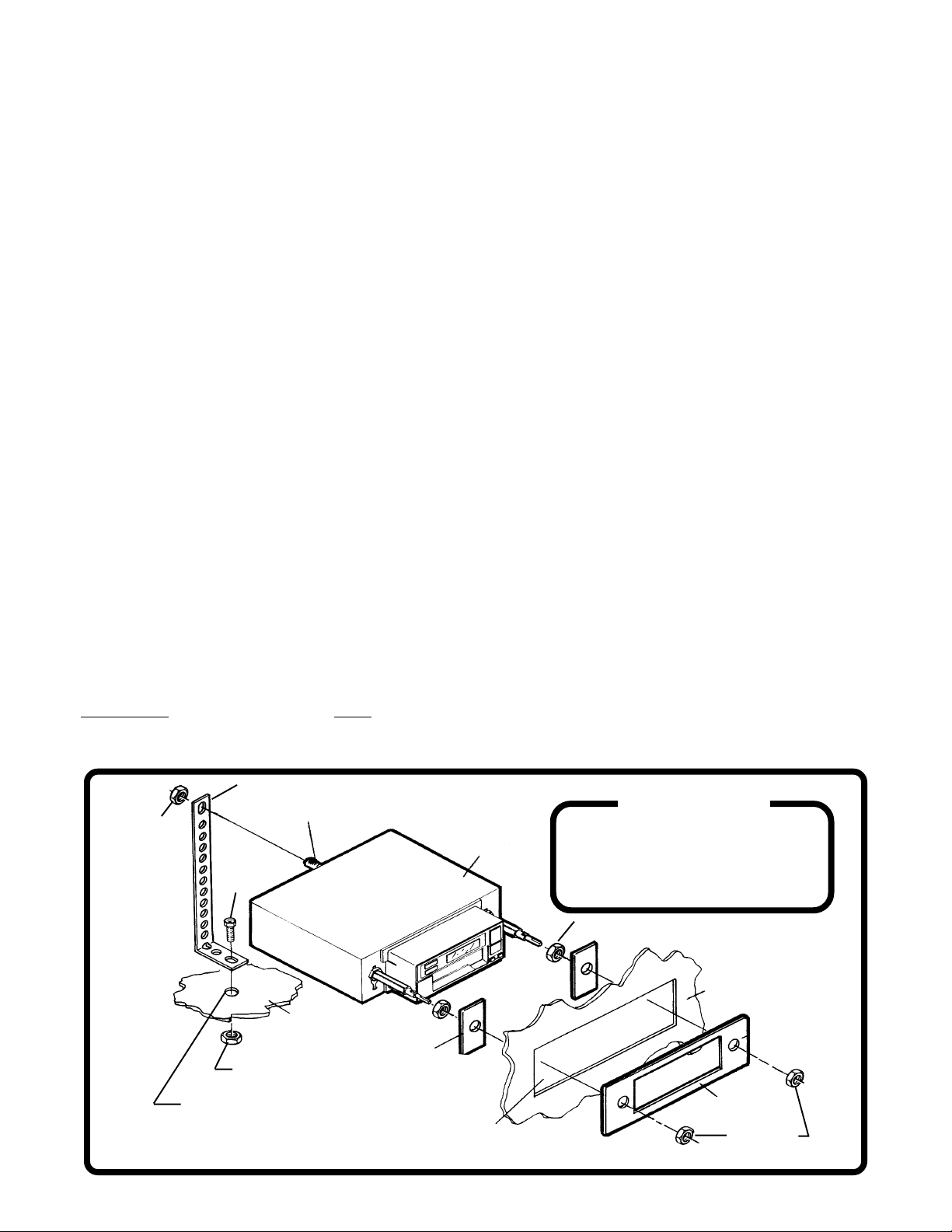
3. Mounting the Radio:
A. Thread a shaft nut half-way down each radio shaft.
B. Place a metal back-up plate on each radio shaft against the shaft nut.
C. Position the radio behind the dashboard opening so that the back-up plates are snug against the back of
the opening. Adjust the shaft nuts behind the back-up plates so that the desired amount of radio extends
through the opening. If possible, the best appearance is usually achieved when there is enough of the radio
extending to be flush with the front of the trimplate.
D. Place the trimplate over the front of the radio and secure it with a shaft nut on each radio shaft.
E. Attach one end of the perforated support strap (supplied) to the screw stud on the radio using the hex nut
provided. Fasten the other end of the perforated strap to a secure part of the dashboard either above or
below the radio using the screw and nut provided. Bend the strap to position it as necessary.
CAUTION: The rear of the radio must be supported with the strap to prevent damage to the dashboard from
the weight of the radio or improper operation of the radio due to vibration.
F. Install knobs on radio shafts.
N EN E
N E
N EN E
ALLALL
ALL
ALLALL
XISTXIST
XIST
XISTXIST
AA
TT
ION FOR VEHICLESION FOR VEHICLES
A
T
ION FOR VEHICLES
AA
TT
ION FOR VEHICLESION FOR VEHICLES
ING RING R
ING R
ING RING R
AA
DIO OPENINGDIO OPENING
A
DIO OPENING
AA
DIO OPENINGDIO OPENING
HEX NUT
PERFORATED STRAP
SCREW STUD
SCREW
METAL PART OF
DASHBOARD
BACK-UP PLATE
HEX NUT
DRILL HOLE IF NECESSARY
EXISTING OPENING
-2-
RADIO
HELP!
1-800-645-49941-800-645-4994
1-800-645-4994
1-800-645-49941-800-645-4994
Monday - Friday
Saturday
SHAFT NUT
8:30am - 7:00pm Eastern
9:00am - 5:00pm Eastern
DASHBOARD
TRIMPLATE
SHAFT NUTS
Page 3
CHECHE
CHE
CHECHE
VRVR
OLET-OLDSMOBILE-BUICK-PONTOLET-OLDSMOBILE-BUICK-PONT
VR
OLET-OLDSMOBILE-BUICK-PONT
VRVR
OLET-OLDSMOBILE-BUICK-PONTOLET-OLDSMOBILE-BUICK-PONT
II
AC-GMC-CAAC-GMC-CA
I
AC-GMC-CA
II
AC-GMC-CAAC-GMC-CA
DILLDILL
DILL
DILLDILL
AC INSTAC INST
AC INST
AC INSTAC INST
ALLALL
ALL
ALLALL
AA
A
AA
TT
T
TT
IONION
ION
IONION
1981 A1981 A
1981 A
1981 A1981 A
Important-This installation is designed for 1981 and older U.S. made GM cars, trucks, and vans. For 1981 and
newer vehicles, an installation kit may be required. See Kit Listing on Page 1 of this manual or refer to the in-store
application chart. If a kit is not required, use the following instructions.
1. Remove the Existing Radio:1. Remove the Existing Radio:
1. Remove the Existing Radio:
1. Remove the Existing Radio:1. Remove the Existing Radio:
A. Remove radio knobs and shaft nuts behind the knobs.
B. Locate and remove support brace at back of radio.
C. Push radio back into dashboard to access the wiring and antenna cables plugged into the rear of the
chassis.
D. Un-plug the wiring harness(es) and antenna cable and remove the radio.
2. Wire the New Radio:2. Wire the New Radio:
2. Wire the New Radio:
2. Wire the New Radio:2. Wire the New Radio:
A. In most cases it is easier to wire the radio before mounting it. Place the radio near the dashboard so the
wires can be led through the opening.
B. Carefully follow the diagram on page 8 to wire the radio, making certain all connections are secure and
insulated with wire nuts or electrical tape to insure proper operation of the unit.
C. After completing the wiring, turn the unit on to confirm operation (ignition switch must be "on"). If unit does
not operate, re-check all wiring until problem is corrected. Once proper operation is achieved, turn off unit
and ignition switch, and proceed with final mounting of the radio.
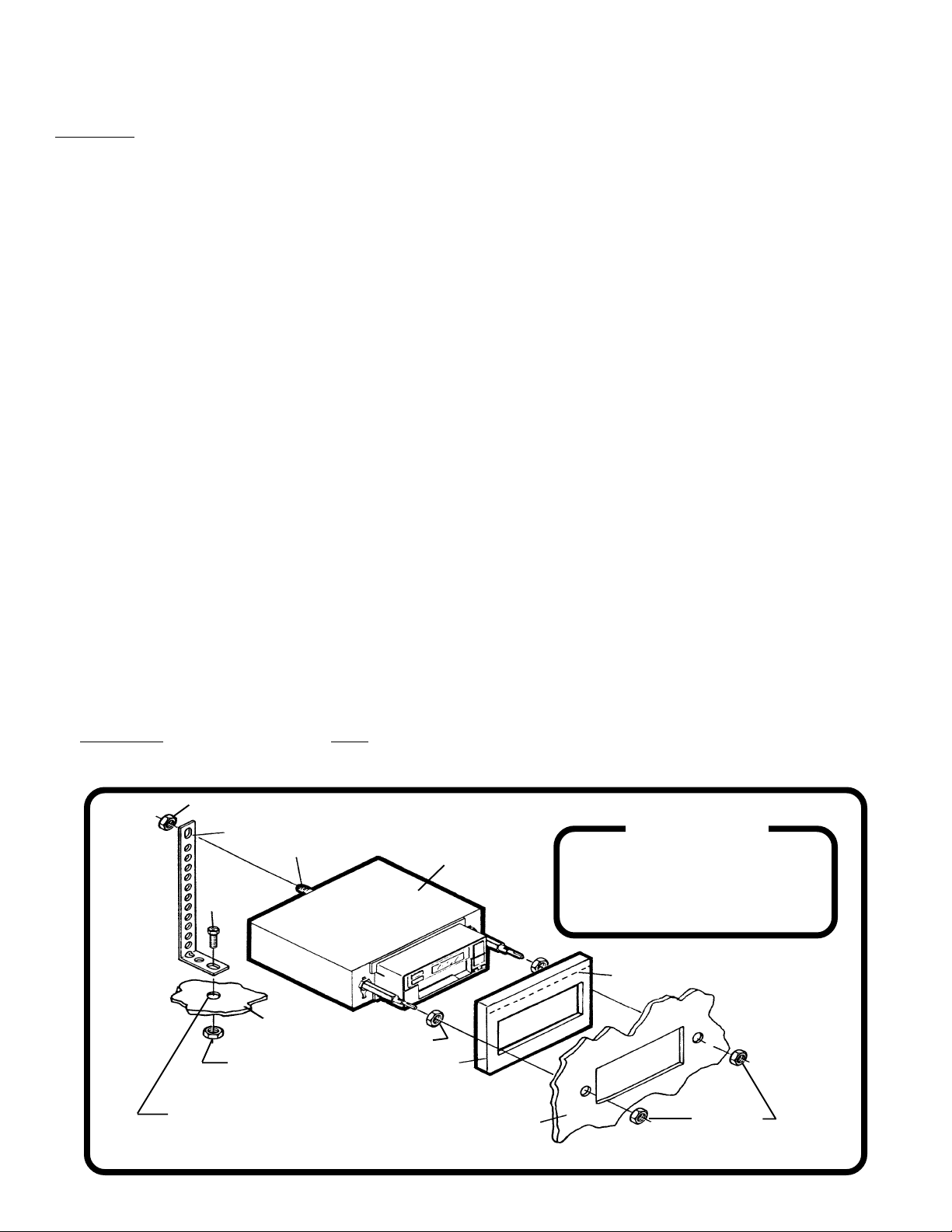
3. Install the New Radio:3. Install the New Radio:
3. Install the New Radio:
3. Install the New Radio:3. Install the New Radio:
A. Thread a shaft nut half-way down each radio shaft.
B. Trim the top edge off of the nosepiece collar at the "CUT OFF FOR GM" mark and place the collar on radio
nosepiece.
C. Place the radio behind dashboard and through the radio opening. Adjust the position of the shaft nuts so
that the radio nosepiece and collar are flush against the back of the dashboard.
D. Secure the radio with a shaft nut on each radio shaft.
E. Attach one end of the perforated support strap (supplied) to the screw stud on the radio using the hex nut
provided. Fasten the other end of the perforated strap to a secure part of the dashboard either above or
below the radio using the screw and nut provided. Bend the strap to position it as necessary.
CAUTION: The rear of the radio must be supported with the strap to prevent damage to the dashboard from
the weight of the radio or improper operation of the radio due to vibration.
F. Install knobs on radio shafts.
ND OLDERND OLDER
ND OLDER
ND OLDERND OLDER
HEX NUT
PERFORATED STRAP
SCREW STUD
SCREW
METAL PART OF
DASH BOARD
HEX
DRILL HOLE IF NECESSARY
NOSE PIECE COLLAR
(INCLUDED WITH RADIO)
SHAFT NUT
RADIO
DASHBOARD
-3-
HELP!
1-800-645-49941-800-645-4994
1-800-645-4994
1-800-645-49941-800-645-4994
Monday - Friday
Saturday
TRIM FOR "GM"
8:30am - 7:00pm Eastern
9:00am - 5:00pm Eastern
SHAFT NUTS
Page 4

CHECHE
CHE
CHECHE
VRVR
OLET-OLDSMOBILE-BUICK-PONTOLET-OLDSMOBILE-BUICK-PONT
VR
OLET-OLDSMOBILE-BUICK-PONT
VRVR
OLET-OLDSMOBILE-BUICK-PONTOLET-OLDSMOBILE-BUICK-PONT
II
AC-GMC-CAAC-GMC-CA
I
AC-GMC-CA
II
AC-GMC-CAAC-GMC-CA
DILLDILL
DILL
DILLDILL
AC-SAAC-SA
AC-SA
AC-SAAC-SA
TURNTURN
TURN
TURNTURN
INSTINST
INST
INSTINST
Important-This installation is designed for most 1982 and newer GM cars, trucks, and vans where an installation
kit is required. See Kit Listing on Page 1 of this manual or refer to the in-store application chart. If a kit is not
required, use the instructions on Page 3.
1. Remove the Existing Radio:1. Remove the Existing Radio:
1. Remove the Existing Radio:
1. Remove the Existing Radio:1. Remove the Existing Radio:
A. Remove the existing dashboard trimpanel surrounding the radio opening. This panel is usually secured
by screws and/or snap-in clips.
B. Remove the screws used to secure the radio to the sub-dashboard.
C. Pull the radio forward to access the wiring and antenna cables plugged into the rear of the chassis.
D. Un-plug the wiring harness(es) and antenna cable and remove the radio.
2. Install the New Radio:2. Install the New Radio:
2. Install the New Radio:
2. Install the New Radio:2. Install the New Radio:
A. Follow the instructions included with the installation kit to attach the radio to the mounting plate supplied
with the kit.
B. Place the radio near the dashboard so the wires can be led through the opening and following the
instructions of Step 2 on Page 2 and diagram on Page 8, carefully wire the radio making certain all
connections are secure and insulated and confirm proper operation.
C. Install the radio/mounting plate assembly to the sub-dashboard according to instructions of installation kit.
D. Attach one end of the perforated support strap (supplied) to the screw stud on the radio using the hex nut
provided. Fasten the other end of the perforated strap to a secure part of the dashboard either above or
below the radio using the screw and nut provided. Bend the strap to position it as necessary.
CAUTION: The rear of the radio must be supported with the strap to prevent damage to the dashboard from
the weight of the radio or improper operation of the radio due to vibration.
E. Replace the dashboard trimpanel.
F. Install knobs on radio shafts.
ALLALL
ALL
ALLALL
AA
TT
ION - 1982 AION - 1982 A
A
T
ION - 1982 A
AA
TT
ION - 1982 AION - 1982 A
ND NEWERND NEWER
ND NEWER
ND NEWERND NEWER
HEX NUT
HEX NUT
MOUNTING PLATE FROM KIT
(NOT INCLUDED WITH RADIO)
IMPORTANT
A MOUNTING KIT IS
REQUIRED
FOR THIS INSTALLATION
PERFORATED STRAP
SCREW STUD
SCREW
RADIO
SHAFT NUT
EXISTING DASH TRIMPANEL
-4-
Page 5

FORD-LINCOLN-MERCURFORD-LINCOLN-MERCUR
FORD-LINCOLN-MERCUR
FORD-LINCOLN-MERCURFORD-LINCOLN-MERCUR
Important-This installation is designed for 1984 and older U.S. made Ford cars, trucks, and vans. For newer
vehicles, an installation kit may be required. See Kit Listing on Page 1 of this manual or refer to the in-store chart.
1. Remove the Existing Radio:1. Remove the Existing Radio:
1. Remove the Existing Radio:
1. Remove the Existing Radio:1. Remove the Existing Radio:
A. Remove radio knobs and shaft nuts behind the knobs.
B. Locate and remove support brace at back of radio.
C. Push radio back into dashboard to access the wiring and antenna cables plugged into the rear of the chassis
D. Un-plug the wiring harness(es) and antenna cable and remove the radio.
2. Wire the New Radio:2. Wire the New Radio:
2. Wire the New Radio:
2. Wire the New Radio:2. Wire the New Radio:
A. In most cases it is easier to wire the radio before mounting it. Place the radio near the dashboard so the
wires can be led through the opening.
B. Carefully follow the diagram on pages 8 to wire the radio, making certain all connections are secure and
insulated with wire nuts or electrical tape to insure proper operation of the unit.
C. After completing the wiring, turn the unit on to confirm operation (ignition switch must be "on"). If unit does
not operate, re-check all wiring until problem is corrected. Once proper operation is achieved, turn off unit
and ignition switch, and proceed with final mounting of the radio.
3. Install the New Radiio:3. Install the New Radiio:
3. Install the New Radiio:
3. Install the New Radiio:3. Install the New Radiio:
A. Thread a shaft nut halfway down each radio shaft.
B. Place the nosepiece collar on the radio nosepiece.
C. Place the radio behind dashboard and through the radio opening. Adjust the position of the shaft nuts so
that the radio nosepiece and collar are flush against the back of the dashboard.
D. Secure the radio with a shaft nut on each radio shaft.
E. Attach one end of the perforated support strap (supplied) to the screw stud on the radio using the hex nut
provided. Fasten the other end of the perforated strap to a secure part of the dashboard either above or
below the radio using the screw and nut provided. Bend the strap to position it as necessary.
CAUTION: The rear of the radio must be supported with the strap to prevent damage to the dashboard from
the weight of the radio or improper operation of the radio due to vibration.
F. Install knobs on radio shafts.
Y INSTY INST
Y INST
Y INSTY INST
ALLALL
ALL
ALLALL
AA
TT
ION - 1984 AION - 1984 A
A
T
ION - 1984 A
AA
TT
ION - 1984 AION - 1984 A
ND OLDERND OLDER
ND OLDER
ND OLDERND OLDER
HEX NUT
PERFORATED STRAP
SCREW
HEX NUT
IMPORTANT
A MOUNTING KIT IS
REQUIRED
FOR THIS INSTALLATION
SCREW STUD
RADIO
NOSE PIECE COLLAR
(INCLUDED WITH RADIO)
METAL PART OF DASHBOARD
DRILL HOLE IF
NECESSARY
DASHBOARD
SHAFT NUTS
-5-
Page 6

FORD-LINCOLN-MERCURFORD-LINCOLN-MERCUR
FORD-LINCOLN-MERCUR
FORD-LINCOLN-MERCURFORD-LINCOLN-MERCUR
Important-This installation is designed for most 1985 through 1990 U.S. made Ford cars, and vans and an
installation kit is required for these vehicles. See Kit Listing on Page 1 of this manual or refer to the in-store
application chart. For 1991 and newer vehicles, the radio can be installed as shown on Page 2 of this manual
or you can use the AX-88-SNP kit. Instructions for use of the AS-88-SNP kit are included with the kit and are not
shown in this manual.
1. Remove the Existing Radio:1. Remove the Existing Radio:
1. Remove the Existing Radio:
1. Remove the Existing Radio:1. Remove the Existing Radio:
A. Remove existing dashboard trimpanel surrounding the radio opening. This panel is usually secured by
screws and/or snap-in clips.
B. Remove the screws used to secure radio to the sub-dashboard.
C. Pull the radio forward to access the wiring and antenna cables plugged into the rear of the chassis.
D. Un-plug the wiring harness(es) and antenna cable and remove the radio.
2. Install the New Radio:2. Install the New Radio:
2. Install the New Radio:
2. Install the New Radio:2. Install the New Radio:
A. Follow the instructions included with the installation kit to attach the radio to the mounting plate supplied
with the kit.
B. Place the radio near the dashboard so the wires can be led through the opening and following the
instructions of Step 2 on Page 2 and diagram on Page 8, carefully wire the radio making certain all
connections are secure and insulated and confirm proper operation.
C. Install the radio/mounting plate assembly to the sub-dashboard according to instructions of installation kit.
D. Attach one end of the perforated support strap (supplied) to the screw stud on the radio using the hex nut
provided. Fasten the other end of the perforated strap to a secure part of the dashboard either above or
below the radio using the screw and nut provided. Bend the strap to position it as necessary.
CAUTION: The rear of the radio must be supported with the strap to prevent damage to the dashboard from
the weight of the radio or improper operation of the radio due to vibration.
E. Replace the dashboard trimpanel.
F. Install knobs on radio shafts.
Y INSTY INST
Y INST
Y INSTY INST
ALLALL
ALL
ALLALL
AA
TT
ION - 1985 AION - 1985 A
A
T
ION - 1985 A
AA
TT
ION - 1985 AION - 1985 A
ND NEWERND NEWER
ND NEWER
ND NEWERND NEWER
PERFORATED STRAP
HEX NUT
HEX NUT
IMPORTANT
A MOUNTING KIT IS
REQUIRED
FOR THIS INSTALLATION
SCREW STUD
SCREW
HELP!
1-800-645-49941-800-645-4994
1-800-645-4994
1-800-645-49941-800-645-4994
Monday - Friday
Saturday
RADIO
EXISTING DASH TRIMPANEL
-6-
8:30am - 7:00pm Eastern
9:00am - 5:00pm Eastern
MOUNTING PLATE FROM KIT
(NOT INCLUDED WITH RADIO)
SHAFT NUTS
Page 7

CHRCHR
CHR
CHRCHR
YY
SLER-DODGE-PLSLER-DODGE-PL
Y
SLER-DODGE-PL
YY
SLER-DODGE-PLSLER-DODGE-PL
YY
MOUTH INSTMOUTH INST
Y
MOUTH INST
YY
MOUTH INSTMOUTH INST
ALLALL
ALL
ALLALL
AA
A
AA
TT
T
TT
IONION
ION
IONION
ALL U.S. MAALL U.S. MA
ALL U.S. MA
ALL U.S. MAALL U.S. MA
Important-This radio cannot be installed in any U.S. made Chrysler, Dodge, or Plymouth vehicle without an
installation kit. Refer to the Kit Listing on Page 1 for the required kit. Complete kit installation is explained in the
instructions included with the kit.
1. Remove the Existing Radio:1. Remove the Existing Radio:
1. Remove the Existing Radio:
1. Remove the Existing Radio:1. Remove the Existing Radio:
A. Remove the existing dashboard trimpanel surrounding the radio opening. This panel is usually secured
by screws and/or snap-in clips.
B. Remove the two large screws used to secure radio to the sub-dashboard.
C. Pull the radio forward to access the wiring and antenna cables plugged into the rear of the chassis.
D. Un-plug the wiring harness(es) and antenna cable and remove the radio.
2. Install the New Radio:2. Install the New Radio:
2. Install the New Radio:
2. Install the New Radio:2. Install the New Radio:
A. Follow the instructions included with the installation kit to attach the radio to the mounting plate supplied
with the kit.
B. Place the radio near the dashboard so the wires can be led through the opening and following the
instructions of Step 2 on Page 2 and the diagram on Page 8, carefully wire the radio making certain all
connections are secure and insulated and confirm proper operation.
C. Install the radio/mounting plate assembly to the sub-dashboard according to instructions of installation kit.
D. Attach one end of the perforated support strap (supplied) to the screw stud on the radio using the hex nut
provided. Fasten the other end of the perforated strap to a secure part of the dashboard either above or
below the radio using the screw and nut provided. Bend the strap to position it as necessary.
CAUTION: The rear of the radio must be supported with the strap to prevent damage to the dashboard from
the weight of the radio or improper operation of the radio due to vibration.
E. Replace the dashboard trimpanel.
F. Install knobs on radio shafts.
DE CADE CA
DE CA
DE CADE CA
RS, TRUCKS, ARS, TRUCKS, A
RS, TRUCKS, A
RS, TRUCKS, ARS, TRUCKS, A
ND VAND VA
ND VA
ND VAND VA
NS BUILNS BUIL
NS BUIL
NS BUILNS BUIL
T SINCE T SINCE
T SINCE
T SINCE T SINCE
19741974
1974
19741974
HEX NUT
HEX NUT
IMPORTANT
A MOUNTING KIT IS
REQUIRED
FOR THIS INSTALLATION
SCREW
PERFORATED STRAP
SCREW STUD
EXISTING DASH TRIMPANEL
-7-
HELP!
1-800-645-49941-800-645-4994
1-800-645-4994
1-800-645-49941-800-645-4994
Monday - Friday
Saturday
RADIO
8:30am - 7:00pm Eastern
9:00am - 5:00pm Eastern
MOUNTING PLATE FROM KIT
(NOT INCLUDED WITH RADIO)
SHAFT NUT
Page 8
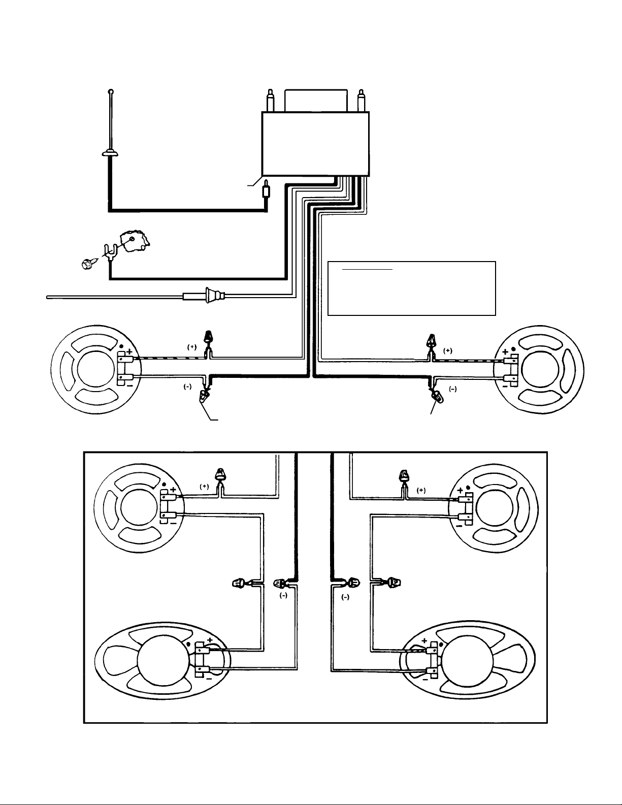
WIRING DIWIRING DI
WIRING DI
WIRING DIWIRING DI
CAUTION: NEVER TURN ON RADIO WITHOUT ALL SPEAKERS CONNECTED. NEVER CONNECT RADIO TO ONLY ONE SPEAKER - A MINIMUM
ANTENNA
ANTENNA SOCKET
ON REAR OF
RADIO
EXISTING ANTENNA CABLE
OF TWO MUST BE USED.
RADIO
AA
A
AA
GRGR
GR
GRGR
AA
A
AA
MM
M
MM
GROUNDED METAL
OF CAR BODY
(REMOVE ANY
BLACK
ORANGE w/WHITE STRIPE FUSED WIRE
LEFT SPEAKER
4 - 8 OHMS
LEFT FRONT SPEAKER
PART
PAINT)
IMPORTANT
CONNECT THE ORANGE w/WHITE
STRIPE WIRE TO THE "RADIO" OR
"ACCESSORY" FUSE IN THE FUSE
BLOCK OF THE VEHICLE.
WHITE
VIOLET
USE WIRE NUTS OR SOLDER AND TAPE ALL SPLICES
WHITE
YELLOW
LIGHT GREEN
YELLOW
RIGHT SPEAKER
4 - 8 OHMS
RIGHT FRONT SPEAKER
VIOLET
LEFT REAR SPEAKER
LIGHT GREEN
4 SPEAKER WIRING USING 4 OHM SPEAKERS
Audiovox Corporation, 150 Marcus Blvd., Hauppauge N.Y. 11788
-8-
RIGHT REAR SPEAKER
Form No.128-4874A
 Loading...