

Page 1
Printed in the U.S.A
INSTALLATION INSTRUCTIONS
FOR
50-0301x-002 SERIES 1181334
50-0301x-014 SERIES 1181332
50-0301x-019 SERIES 1181336
FORD EXPLORER / MERCURY MOUNTAINEER
VCP HOUSING
These instructions are intended for use only by experienced professionals in the automotive
customizing business. Special tools and equipment, as well as specialized handling and care
of product during installation, may be required. Before beginning this installation, carefully
read through the following instructions. Check for wiring or other componentry behind VCP
area before installing.
Materials/ Tools required for this installation:
1. #2 Phillips screwdriver 2. Powered screwdriver or drill with adapter
3. Awl or similar tool 4. Razor knife or similar
5. Audiovox VCP (AVP-7180 or equiv.)
INSTALLATION INSTRUCTION # 44-0040A
Nov. 8, 1999
Page 2
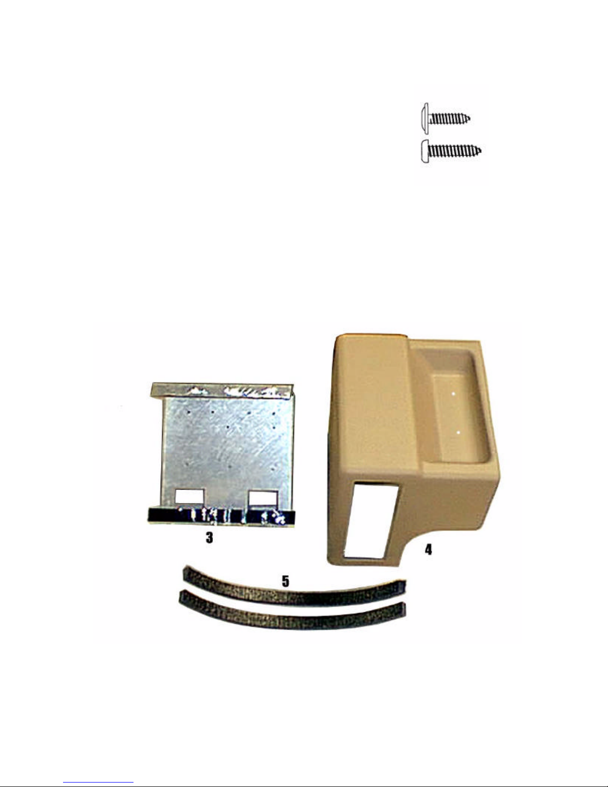
MATERIALS PROVIDED FOR INSTALLATION:
ITEM Description QTY
1
SCREW, # 8X 9/16" PWH
10
2
SCREW, # 8 X 3/4" PPH
2
3
VCP MOUNTING BRACKET
1
4
5
VCP HOUSING
FOAM TAPE, 3/4" X 3/4" X 14"
1
2
1
2
INSTALLATION INSTRUCTION # 44-0040A Nov. 8, 1999
2
Printed in the U.S.A.
Page 3

I. PREPARATION OF VEHICLE INTERIOR
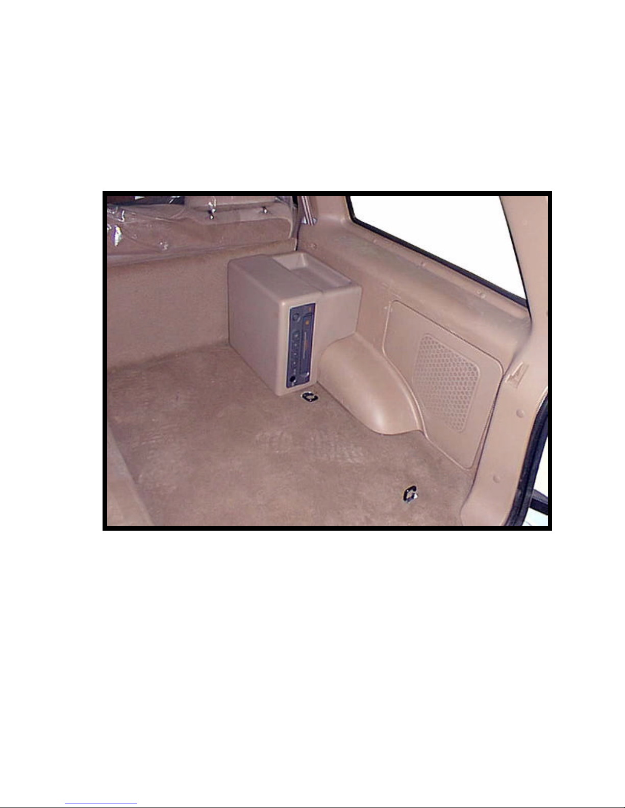
FIGURE 1
3. Install and route all video and audio cables, and
any other added component requirements to their
respective places in the vehicle. Refer to
component installation instructions for wiring
diagrams. The suggested routing of the video
system cable is as follows: Above the headliner
from video system to C-pillar. Down the C-pillar to
the floor. Route the power lead to a fused
accessory controlled source. Connect the ground
lead to the vehicle chassis. Route the remaining
wiring (RCA plugs, Remote Sensor extension, etc.)
to the VCP location. See Figure 2. Connect per
instructions included with the video system. If
video system if to be used as a television, install an
appropriate antenna per instructions included with
the antenna.
II. INSTALLATION OF HOUSING
4. Remove and retain (2) two # 8 X 9/16" screws (item 1
Do not overtighten screws.
3
FIGURE 3
1. Retract storage cover, remove from location
and lay it in a safe place. See Figure 1.
2. Fold rear seat forward.
FIGURE 2
pg 2 ) from VCP housing assembly. Separate VCP
housing (item 4 pg 2) from mounting bracket (item 3
pg 2). Install mounting bracket as shown in Fig. 3.
Secure using (8) eight # 8 X 9/16" screws (item 1
pg 2).
Page 4

5. Remove and discard (2) two screws from the left
side of VCP. See Figure 4.
FIGURE 5
9. Place VCP housing (item 4 pg 2) over VCP.
Lightly mark the location where housing mates
to side panel. Remove VCP housing.
FIGURE 4
6. Insert VCP into mounting bracket (item 3 pg 2) as
shown in Figure 5. Route wiring through opening
in VCP bracket. Connect all wiring to VCP per
instructions included with video system.
7. Check function of all components. See operating
instruction for video system operations check. For
further assistance, refer to the video system manual
for the technical support phone number listed for
your area.
8. Secure VCP to mounting bracket using (2) two # 8
X 3/4" screws (item 2 pg 2) into original holes in
VCP. Do not overtighten screws. See Fig. 5.
FIGURE 6
4
Page 5

FIGURE 7
12. Install VCP housing (item 4 pg 2) and secure to
mounting bracket using (2) two # 8 X 9/16" screws,
removed in step 4. (item 1 pg 2). See Fig. 8. Make
sure Velcro tape adheres to bottom of VCP housing.
10. Install foam tape (item 5 pg 2) along each side of
mounting bracket where lines were previously
marked. See Figure 7.
11. Remove adhesive backing from Velcro tape along
bottom of VCP bracket. See Figure 7.
FIGURE 8
13. Trim floor mat, if applicable, to fit around VCP
housing. See Figure 9.
14. Raise seat into locked upright position.
15. Replace storage cover, if applicable, in original
location.
FIGURE 9
5
 Loading...