

Page 1
Printed in the U.S.A
INSTALLATION INSTRUCTIONS
FOR
50-0285x-015 SERIES 1181279
CHEVROLET VENTURE
OVERHEAD CONSOLE for use with FLIPDOWN VIDEO SYSTEM
These instructions are intended for use only by experienced professionals in the automotive
customizing business. Special tools and equipment, as well as specialized handling and care
of product during installation, may be required. Before beginning this installation, carefully read through
the following instructions. Use extreme care when cutting headliner material.
Check for wiring or other componentry above headliner material. Cut only where indicated.
Materials/ Tools required for this installation:
1. #2 Phillips screwdriver 2. Powered screwdriver or drill with adapter
3. T-15 TORX bit driver 4. Razor knife or similar
5. Awl or similar tool 6. 1/4” hex socket bit
7. 18 GA wire 4' 8. Audiovox Series 640/650 Video Module
NOT FOR VEHICLES EQUIPPED WITH SUN ROOF.
INSTALLATION INSTRUCTION # 44-0034A
MATERIALS PROVIDED FOR INSTALLATION:
June 2, 1999
Page 2
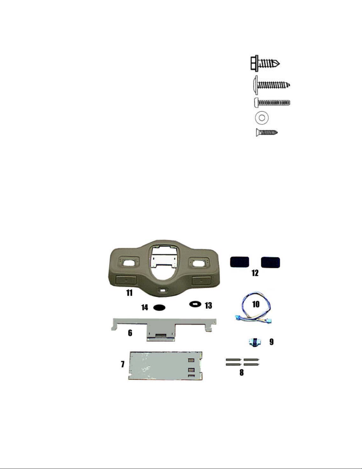
ITEM Description QTY
1
2
3
4
5
6
7
8
9
10
11
12
13
14
SCREW, # 10 X 1/2" HWH 7
SCREW, # 8 X 3/4" PWH 6
SCREW, 6-32 x 3/4" PPH 6
WASHER, # 6 4
SCREW, # 6 X 1/2" PFH 2
FRONT MOUNTING BRACKET 1
REAR MOUNTING BRACKET 1
SWITCH MOUNTING BRACKET 4
ADAPTER 1
WIRE HARNESS 1
CONSOLE 1
SPEAKER GRILLE 2
COVER PLATE 1
COVER PLATE DECAL 1
1
2
3
4
5
INSTALLATION INSTRUCTION # 44-0034A
2
I. PREPARATION OF VEHICLE INTERIOR
June 2,1999
Printed in the U.S.A.
Page 3

IF VEHICLE IS NOT EQUIPPED WITH FACTORY REAR A/C AND REAR AUDIO CONTROLS,
PROCEED TO STEP 4.
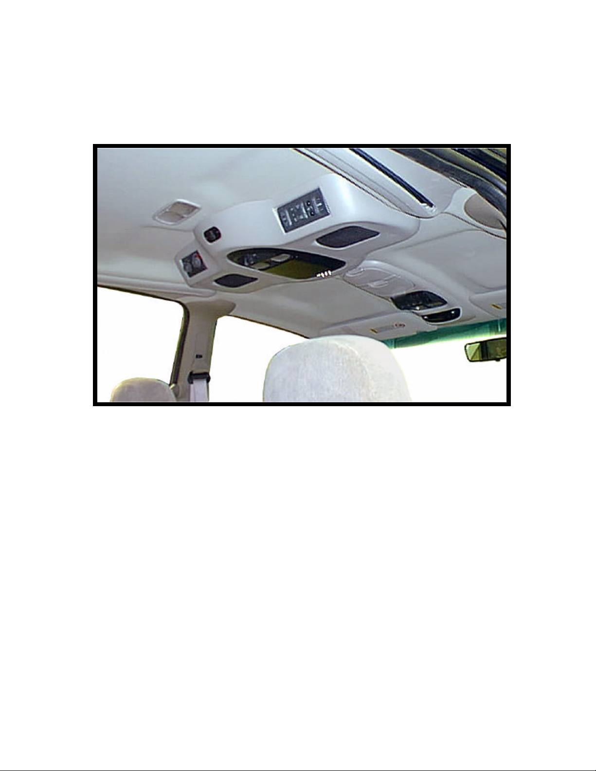
1. Carefully remove the O.E.M. console mounted to
inner roof of vehicle by pulling downward on sides to
release clips. See Figure 1.
2. Lower console and disconnect wiring at (3) three locations.
Remove and retain controls from console and lay them in
FIGURE 1
a safe place. Discard console. See Fig. 2.
3. Remove and retain (2) two O.E.M. screws which
4. Using a razor knife, carefully trim headliner as shown.
FIGURE 3
Make sure the 27” cut is centered left to right in vehicle.
Caution: Before cutting headliner material,
check for wiring or other componentry above
headliner. Cut only where indicated.
DO NOT OVERCUT HEADLINER. See Figure 4.
5. Remove and retain O.E. dome light. Caution: Headliner
material is brittle. Use care when removing dome
light. Access dome light clip through opening
previously cut in headliner.
6. Scribe a center line on the sheet metal roof of vehicle.
FIGURE 2
secure plastic panel. Slide panel rearward until front
edge of panel can be lowered through headliner.
Slide forward and discard panel. See Figure 3.
3
FIGURE 4
Page 4

7. Remove and retain (2) two screws which secure front
brace. Make sure that bracket engages securely.
mounting bracket (item 6 pg. 2) to console (item 11 pg
2). Install front mounting bracket over O.E. brace,
align slot with center line scribe and front edge of the
O.E. brace. Make sure that the bracket is centered
left to right. If applicable align and fasten O.E. screws
in O.E. clips in the roof of the vehicle. Secure using
(4) four # 10 x1/2" screws (item 1 pg. 2). See Fig. 5.
8. Inset rear mounting bracket (item 7 pg. 2), with bent
edges upward, between headliner and sheet metal roof.
Slide bracket rearward until tabs engage rear O.E.
Align slots in bracket with the center line scribed in the
roof. Secure brackets together using (3) three #
10 x1/2" screws (item 1 pg. 2). See Figure 5.
FIGURE 5
9. Install jumper wire harness (item 10 pg 2) to
extend the O.E.M. audio control harness, if
equipped. See Figure 6.
FIGURE 6
II. PREPARATION OF CONSOLE FOR INSTALLATION
IF VEHICLE IS NOT EQUIPPED WITH FACTORY REAR A/C AND REAR AUDIO CONTROLS,
PROCEED TO STEP 13.
10. Carefully remove cover from respective switch
location on console (item 11 pg 2) if applicable.
See Fig. 7.
11. Using a razor knife, trim away tab.
FIGURE 7
12. Install A/C switch on driver’s side opening and audio
controls on passenger’s side opening. Note: Make sure
switches and controls are installed in the proper
direction. Remove backing from tape on switch mounting
brackets (item 8 pg 2) and install (1) one bracket on top
and (1) one on bottom of each switch. Press firmly on
brackets to secure to switch and inside of console.
4
FIGURE 8
Page 5

IF SPEAKER UPGRADE KIT WAS PURCHASED,
INSTALL PER INSTRUCTIONS PROVIDED.
SEE FIGURE 9 FOR SUGGESTED LOCATIONS.
FIGURE 9
III. INSTALLATION OF CONSOLE
NOTE: Additional assistance in mounting the overhead console in vehicle is advised to prevent
damage to console or components. Caution: Do not overtighten screws. Use extra support
for the console until secured to the vehicle, failure to do so may cause damage to console or
installed components.
13. Install and route all video and audio cables, and any other added component requirements to their respective
places in the vehicle. Refer to component installation instructions for wiring diagrams. The suggested
routing of the video system cable is as follows: Above the headliner from video system to B-pillar. Down
the B-pillar to the floor and underneath scuff panel. Up the passenger’s side kick panel and across the
bottom side of dash panel. Route the power lead to a
fused accessory controlled source. Connect the ground
lead to the vehicle chassis. Route the remaining wiring
(RCA plugs, Remote Sensor extension, etc.) to the
VCP location. See Figure 10. Connect per instructions
included with the video system. If video system if to be
used as a television, install an appropriate antenna per
instructions included with the antenna.
14. Construct a jumper harness that will connect the vehicle’s
dome light to the black and white wires from the lights in
video system.
FIGURE 10
15. Raise console (item 11 pg. 2) into approximate position and connect all wiring to components.
16. Position console against headliner. Loosely install
using (2) two 6-32 x 3/4” screws (item3 pg.2) through
the smaller holes in bracket on console into threaded
clips on front mounting bracket. See fig. 11.
17. Using a scribe or similar tool, align holes in speaker
area with slots in mounting bracket. Loosely secure
sides of console using (2) two #8 x 3/4" screws (item
2 pg. 2). See figure 11. Make sure console alignment
is straight, then tighten all screws.
18. Release video screen from locked position. Lower
video screen to viewing position for access to
5
FIGURE 11
Page 6

mounting location in top of video system housing.
bet
wee
n
vide
19. Raise video system into approximate position and connect all wiring to components. Connect wiring and
cabling to video system per instructions included
with video system.
20. Check function of all components and lights. See
operating instructions for video system operations
check. For further assistance, refer to the video
system manual for the technical support phone
number listed for your area.
21. Insert video system into opening in console.
Note : Make sure wires do not get pinched
FIGURE 12
o system and console .
22. Align holes in housing with clips in mounting bracket. Secure using (4) four 6-32x 3/4" screws
(item 3 pg.2) and (4) four #6 washers (item 4 pg. 2). See Figure 12.
Caution : Do not overtighten screws.
23. Raise video screen into locked position.
24. Install speaker grille (item 12 pg 2). Align clips in
grille with holes in console and press firmly. See
Fig. 13.
25. If speaker upgrade kit was not installed, install
cover plate (item 13 pg 2) at rear of console and
secure using (2) two # 6 X 3/8" screws (item 5
pg 2). See Figure 13.
26. Install cover plate decal (item 14 pg 2).
27. Install dome light in original manner.
FIGURE 13
6
 Loading...