

Page 1
Printed in the U.S.A
INSTALLATION INSTRUCTIONS
FOR
50-0286x-019 SERIES 1181278
CHEVROLET VENTURE VCP HOUSING
These instructions are intended for use only by experienced professionals in the automotive
customizing business. Special tools and equipment, as well as specialized handling and care
of product during installation, may be required. Before beginning this installation, carefully read
through the following instructions. Use extreme care when cutting headliner material.
Check for wiring or other componentry above headliner material. Cut only where indicated.
Materials/ Tools required for this installation:
1. #2 Phillips screwdriver 2. Powered screwdriver or drill with adapter
3. 3/16" hex socket 4. 7mm hex socket
5. Awl or similar tool 6. Audiovox VCP (AVP-7180 or equiv.)
INSTALLATION INSTRUCTION # 44-0035A
Mar. 11,1999
Page 2
MATERIALS PROVIDED FOR INSTALLATION:
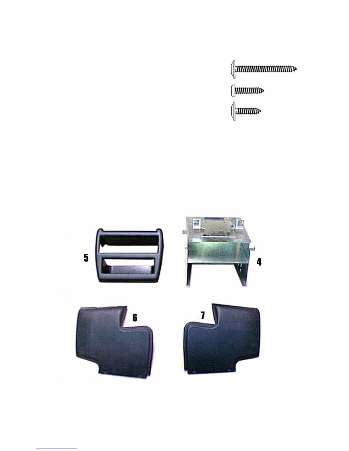
ITEM Description QTY
1
2
SCREW, # 8 X 1 1/2" PWH 2
SCREW, # 8 X 3/4" PWH 2
2
3
4
5
6
7
SCREW, # 8 X 9/16" PWH 8
VCP MOUNTING BRACKET 1
BEZEL 1
DRIVER SIDE PANEL 1
PASSENGER SIDE PANEL 1
1
3
I. PREPARATION OF VEHICLE INTERIOR
INSTALLATION INSTRUCTION # 44-0035A
2
Mar. 11, 1999
Printed in the U.S.A.
Page 3

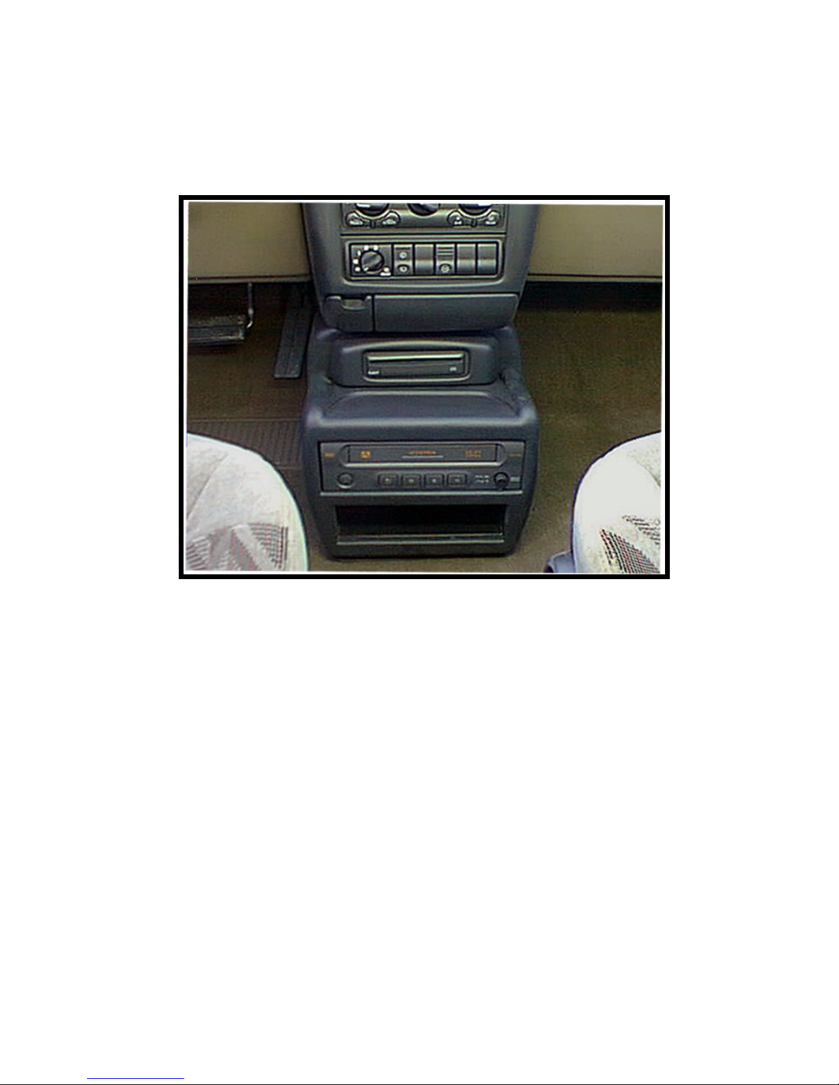
1. Open door on O.E. center console. Using a 7mm
socket, remove and discard (2) two screws which
secure lower O.E. console. See Figure 1.
FIGURE 1
2. Slide console outward from original position and
disconnect wiring from CD player. See Figure 2.
3. Remove and retain (2) two heater vents. See Fig. 2.
FIGURE 3
II. PREPARATION OF COMPONENTS FOR INSTALLATION
FIGURE 2
4. Remove and retain CD player bezel. Remove by
prying outward to release clips. See Figure 3.
NOTE: If vehicle is equipped with storage
pocket instead of CD player, remove and
retain storage pocket.
3
Page 4

5. Depress tabs which secure CD player in console.
Slide outward to remove CD player from
console. See Figure 4.
FIGURE 5
8. Remove and retain plastic parts from mounting bracket
(item 4 pg.2 ) lay them in a safe place. Install CD player
onto mounting bracket. See Figure 6.
NOTE: Make sure that tabs are inserted into
bottom of CD player.
NOTE: If vehicle is not equipped with CD player
fold tabs downward.
III. INSTALLATION OF CONSOLE
4
FIGURE 4
6. Remove the (2) screws which secure bracket to
the CD player. See Figure 5.
7. Tilt bracket downward and outward to remove
bracket from CD player.
FIGURE 6
Page 5

10. Align holes in rear of CD player with holes in mounting
FIGURE 7
bracket.
11. Secure CD player to mounting bracket using the (2) two
original screws. See Figure 8.
12. Place mounting bracket in vehicle in approximate position
where original console was located.
13. Connect CD wiring and insert video cables and wiring
through opening in rear of mounting bracket.
14. Position mounting bracket against plastic panels
NOTE: Tabs on lower bracket aligns with slots
15. Using an awl or similar tool align holes in
16. Secure mounting bracket using (2) two #8 X
1 1/2" screws (item 1 pg. 2). See Figure 9.
FIGURE 9
9. Route video and audio cables from overhead
console location to passenger’s side B pillar.
Down B pillar and underneath scuff panel.
Up passenger’s side kick panel and across the
bottom side of dash panel. See Figure 7.
FIGURE 8
that original console secured to.
on bracket on floor of vehicle.
bracket with holes in plastic panel and threaded
clips behind panel. See Figure 9.
5
Page 6

17. Remove and discard the front (2) two screws of the
VCP cabinet. See Figure 10.
18. Insert VCP into mounting bracket and make all
necessary wiring connections. Check function of
19. Slide VCP inward until rear of VCP contacts tab in
20. Secure VCP with (2) two #8 X 3/4" screws (item 2
FIGURE 10
VCP. See operating instructions included with
components. For further assistance, refer to the video
system manual for the technical support phone number
listed for your area.
rear of mounting bracket. See Figure 11.
pg.2 ) in original holes where screws were previously
removed. See Figure 11.
FIGURE 11
21. Install the (2)two heater vents in original manner.
22. Install the O.E. CD player bezel (previously removed)
in original manner. See Figure 12.
NOTE: If vehicle is not equipped with a CD player,
install O.E. storage pocket in original manner.
23. Install the side panels (items 6 & 7 pg.2) and secure
using (2) two #8 X 9/16” screws (item 3 pg.2) on each
side. Use an awl or similar tool to align holes in side
panel with holes in bracket.
NOTE: Make sure that the heater vents engage the
original side panel. See Figure 12.
24. Install bezel (item 5 pg. 2.) and secure using (4) four
#8 X 9/16" screws (item 3 pg. 2). See Figure 12.
6
FIGURE 12
 Loading...