

Audio Valve Sunilda Owners manual

W A R R A N T Y
AUDIOVALVE warrants its components for a three-year period on all electronics and a 90-day period on
the tubes from the purchase date.
In the event of a failure of your amplifier, AUDIOVALVE will repair or readjust this unit or, should the
occasion arise, will replace it provided that all conditions stipulated in this warranty are met.
In order to initiate service of any kind it is necessary to obtain distributor or dealer authorization prior to
shipping the unit for service.
Any of the following conditions shall void the warranty:
Operation not in accordance with this manual.
Abuse , accidental damage or unauthorized modifications , as determined by AUDIOVALVE or its
agents exclusively.
Removal, defacing or falsifying of the serial numbers.
Shipping without the original complete factory crates.
WARRANTY REGISTRATION
Please fill out and return this warranty form to the distributor within 15 days of the purchase date,
or fill out our online warranty registration form at: www.audovalve. info
MODEL : _______________________________________________
SERIAL NUMBER : _______________________________________
PURCHASE DATE : ______________________________________
AUTHORIZED AUDIO - VALVE DEALER:
PURCHASER`S NAME : ___________________________________
STREET ADDRESS : ______________________________________
CITY : __________________________________________________
ZIP / POSTAL CODE : _____________________________________
The two middle rotary knobs select low impedances for MC
systems in the first five switch positions starting from the left.
The last position at the very right of these switches has a
47kOhm load and is intended for use with MM systems.
So for MC systems chose the impedances 47 R-1 k in the first five
switch positions and select the impedance in the sixth switch
position (MM 47k), if a MM system has been connected to this
input.
According to your requests all switch positions may be combined in
any order thus allowing the simulation of a large number of
different loads for your pick-ups.
Note:
Always turn down the volume at the pre-amplifier to safeguard
your speakers when changing the following settings at SUNILDA:
1) When switching over from one input to another input.
When switching from MM to MC, because the amplification increases by 20dB.
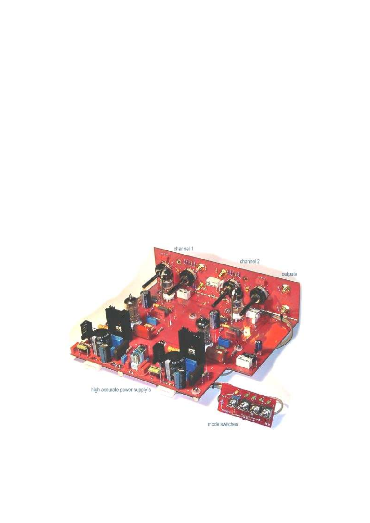
A view of the compact and absolute wireless electronic - riaa modul from SUNILDA. There is no
hum, bee or any noise - only music. The design on a double side pc board is constructed in double
mono technology, use best and selected components and guarantee high stable and highend venyl
re - productions.

If connecting only one system, please use the input 1 according to
the marking at the back of the appliance. Make sure the cinch
cables as well as the adjacent earth conductor are well fitted.
At the right of the front screen you will find a row of flip
switches. Only the switch in the middle to be actuated at level
indicates the input to be used by yourself. Flip this switch to the
left, if you have configured to input 1 at the back. Flip it to the
right, if you have also configured to input 2 and intend to use both
inputs.
There is an additional switch each at the right and at the left of
the level flip switch to be actuated vertically assigning the
connected pick-up by model to the respective input. The flip
switch is flipped upwards, if a MC system is connected to the
respective input and is flipped downwards when connecting a MM
system.
The very left switch of all 4 flip switches can mute the output
signal, if being flipped upwards (yellow LED) or can change into
stand-by mode (red LED) with the switch pointing downwards.
In this case SUNILDA is heated up without anode supply voltage.
With the switch in neutral position none of these two functions
are active. This switch position is neutral and usually the prefered
position.
Relevant information:
Whenever one of these 4 flip switches is actuated, the outputs of
the phone pre-amplifier are muted for a period of 30 secs. to
suppress the internal voltage variations at the output. This is for
safety control only.
IMPEDANCE
By means of the four rotary knobs at the left side of the front
screen the impedances for the pick-up's are selected for both
outputs independantly from each other.
Looked at from the middle the knobs are in a mirror-inverted
position, i.e. the two middle rotary knobs select the load
resistance for the pick-ups: the middle left knob for input 1 and
the middle right knob for input 2.
By means of the outer rotary knobs the appropriate leading load
for the individual input is selected. You may change these settings
at the amplifier, if required.

Set-up and installation of the Phono Amplifier SUNILDA
After having unpacked your phono equipment set the phono preamplifier up at its chosen place. The power supply should be
positioned at a distance from the pre-amplifier by at least the
length of the connecting cable.
Equally, other large electrical consumers should not be positioned
near SUNILDA and the record player. The power supply can be
best placed on the floor, however make sure the power switch on
the front of the power supply is visible and within reach.
Only when manipulating this main switch on the power supply
SUNILDA is either made alive or, after having switched off, is
completely dead identification by means of a red LED at the
right front of the power supply.
The LED shines, if the pre-amplifier is switched off at the switch
on the front of the amplifier, with the power supply, however
remaining alive. The red LED signals that the power supply is still
alive.
In case the amplifier will not be used for a longer period of time,
as f.Ex. in holiday times, make sure the amplifier as well as the
power supply is cut off!
After having set-up both appliances at first connect power supply
and amplifier with the included CENTRONICS cable and secure
the cable against falling out at both ends.
Subsequently connect the power supply to mains voltage by means
of the powercord.
Ensure that the power supply is CUT OFF with no LED shining at
the appliance.
Now start to instal the signal lines between the pickup and
SUNILDA. Fix the earth conductor of the record player to the
earth terminal assigned to each input at the back of the preamplifier next to the cinch inputs.
Cable the output of the SUNILDA phono pre-amplifier to your
EKLIPSE pre-amplifier using the appropriate cinch cables.
The pre-amplifier is still cut off. When putting the power supply
into operation, the red LED at the right front of the amplifier
below the ON OFF switch begins to shine.
Before you also connect the pre-amplifier, check the settings for
the pick-up at the appliance .
 Loading...