

AudioValve Challenger 400 User Manual

INSTRUCTION
manual
for
CHALLENGER 400
MONO POWER AMPLIFIER
_____________________________________
This handcrafted product was special made for your high demands,
to display the music on its finest way.
We guarantee that this amplifier was carefully produced
and tested in all details.
rev.01.2013
_____________________________________________________________________

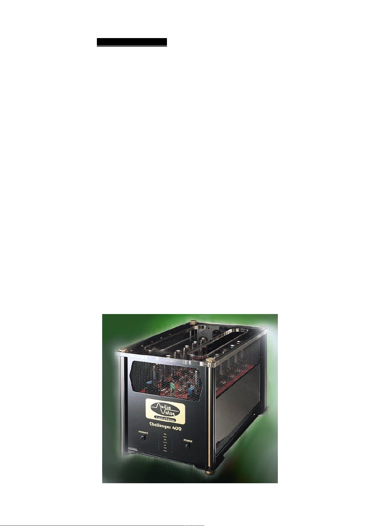
Challenger 400 power tube amplifier ____
Congratulations on your decision to become the proud owner of the
AUDIO-VALVE Challenger power amplifier.
This manual has been prepared to help you understand the operation
of your amplifier and to provide some information about its design and
the variety of ways it may be used.
We have designed and manufactured this amplifier to faithfully and
accurately reproduce music. This hand build instrument should give
a lifetime of pleasure and with a little care and a full understanding
of the operation recommendation in this manual the Challenger
should provide trouble free performance.
List of contents
- Warning and precautions
- Front panel - rear panel
- Drawing front panel
- Drawing rear panel
- Input - output terminals
- Polarity - phasing
- Installation and operation
- Automatic bias control ( ABR )
- Specifications
- misc.

Challenger 400 power tube amplifier ___
WARNING
This amplifier Challenger operates in class - A and is
therefore capable of generating a moderately high temperatue
which requires careful placing to aviod any effect this heat
may have on other equipment, furniture and fittings etc.
Do not remove the top cover from this ampllifier.
Hazardous voltages are present. Any repair work should
be referered to a suitable qualified and experienced
service person.
Do not attempt to connect any input of this amplifier to
any of its outputs.
Do not earth any output terminal or connect any of these
terminals together without following the instructions in
this manual or seeking qualified assistance.
Do not place this amplifier in any position where liquids
or any foreign material may accidentally enter it.
Do not disconnect any in / output wire, while the amplifier is
operating.
Do not connect any voltage source short circut, earth / ground
or appliance (other than suitable HiFi quality loudspeakers )
to any output terminal.
Some preamplifiers, proccesors, CD players etc produce
large switching pulses when switched on, causing a loud
click through the loudspeakers. For this reason, turn on
all other equipment in your system and operate the
Stand - by mode of the amplifier before turning on the Challenger.
Note: the Challenger power amplifier do not cause this problem.
Challenger 400 power tube amplifier ____
FRONTPANEL
The front panel of the Challenger power amplifier
incorporates with a small panel filled with two switches.
These switches control the day to day function of the amplifier.
The operation of this two switches is like following:
MAIN SWITCH
This heavy duty rocker switch is at the right side
of this panel and switched the mains / line power of the
amplifier On or OFF. A blue LED immediatly beside the
switch illuminates to indicate that the power is ON.
This amplifier draws on moderate high current when
switched on. It is not good practice to repeatedly
active this switch ON and OFF rapidly.
STAND - BY SWITCH.
This switch on the left of the panel alters the operation
STAND BY of the amplifier. Switch down is operation
STAND BY , ( the blue LED`s is off).

Challenger 400 power tube amplifier ____
REAR PANEL
The facilities on the rear panel of the Challenger may
seem not so complex. The rear panel incorporates all
of the terminals for connencting the input signals and
the output signals to the loudspeaker. A reasonable
understanding of this amplifier and the logical approach
should ensure that you are listening to this amplifier in a
very short space of time without any difficults at all.
Please remember that the AUDIO VALVE Challenger
power amplifier is a high quality electronic instrument
capable of an exceptional level of performance.
Be sure that you are understanding your requirements fully
before you make any connection to this amplifier.
INPUT TERMINALS
Input terminals for this Challenger power amplifier are easily
accessible and fitted to the lower centre area of the rear panel.
RCA INPUT. These standard type of RCA terminals are for
use with unbalanced signals from most sigal sources such as
audio preamplifiers.
XLR BALANCED INPUT. XLR connector fitted to
the amplifier are for use with balanced line signals from
audio preamplifiers etc. Balanced signals are carried
via a three way cable that connects all three pins at each
of the interconnect cable.
DO NOT operate this amplifier with both RCA and XLR
cables connect at the same time.
When using the RCA connector, please place at the XLR input a
" Dummy " plug, which has an intern short connection between
gnd. and minus phase.
 Loading...