

Page 1

INSTRUCTION
owner - manual
Assistent 50
Intergrated Stereo class -a tetrode tube amplifier
This handcrafted product was special made for your high demands,
to display the music on its finest way.
We guarantee, that this amplifier was carefully produced
and tested in all details.
_________________________________________________________
Congratulations on your decision to become the proud owner of the
AUDIO VALVE Assistent 50 amplifier.
Page 2

Assistent 50 integrated tube amplifier_____________________
This manual has been prepared to help you understand the operation of your
amplifier and to provide some information about its design and the variety of
ways it may be used.
We have designed and manufactured this amplifier to faithfully and accurately
reproduce music. This hand build instrument should give a lifetime of pleasure
and with a little care and a full understanding of the operation recommendation
in this manual the Assistent 50 should provide trouble free performance.
Please take time to read this manual
thoroughly before using your amplifier.
There should be two persons grabbing the outer rim of plexiglas top to lift up,
rest on edge of crate then continue all lifting from the bottom of the chassis.
List of contents
- Warning and precautions
- Front panel - rear panel
- Drawing front panel
- Drawing rear panel
- Input - output terminals
- Polarity - phasing
- Installation and operation
- Automatic bias control ( ABR )
- Specifications
WARNING
This amplifier Assistent 50 operates in class - A and is
therefore capable of generating a moderately high temperature which requires
care full placing to aviod any effect this heat may have on other equipment,
furniture and fittings etc.
Do not remove the top cover from this amplifier.
Hazardous voltages are present. Any repair work should
be refer to a suitable qualified and experienced
service person.
Do not attempt to connect any input of this amplifier to
any of its outputs.
Do not earth any output terminal or connect any of these
terminals together without following the instructions in
this manual or seeking qualified assistance.
Page 3

Assistent 50 integrated tube amplifier_____________________
Do not place this amplifier in any position where liquids
or any foreign material may accidentally enter it.
Do not disconnect any in / output wire, while the amplifier is
operating.
Do not connect any voltage source short circuit, earth / ground or appliance
(other than suitable HiFi quality loudspeakers ) to any output terminal.
Some preamplifiers, processor, CD players etc produce
large switching pulses when switched on, causing a loud
click through the loudspeakers. For this reason, turn on
all other equipment in your system before turning on the
Assistent 50.
All handling at the open amplifier has to be done
when the main power plug is disconnected .
Please notice that you never exceed the mains voltage in the prescribed value
shown at the lable of the serial number on the rear side. If you can`t provide the
amplifier with the exact shown main voltage, please use a voltage stabilizer
- particulare for the US market and Mainland China
The amplifier needs a certain time to form the brand new
components (capacitors) otherwise they can be destroyed.
Use the Stand - By mode for warm hold periodes ( tube heating ) the amp
without listening. Do not leave your house when the amp works use on
equipment, or during sleeping time.
Please only do use your amplifier while listening to music.
Note: the Assistent 50 amplifier do not cause this problem.
Page 4
Assistent 50 integrated tube amplifier_____________________
FRONT PANEL
Beside the volume knob there are no manual handlings on the front panel.
The Assistent 50 is purely remote controlled designed, this includes also the
volume control.
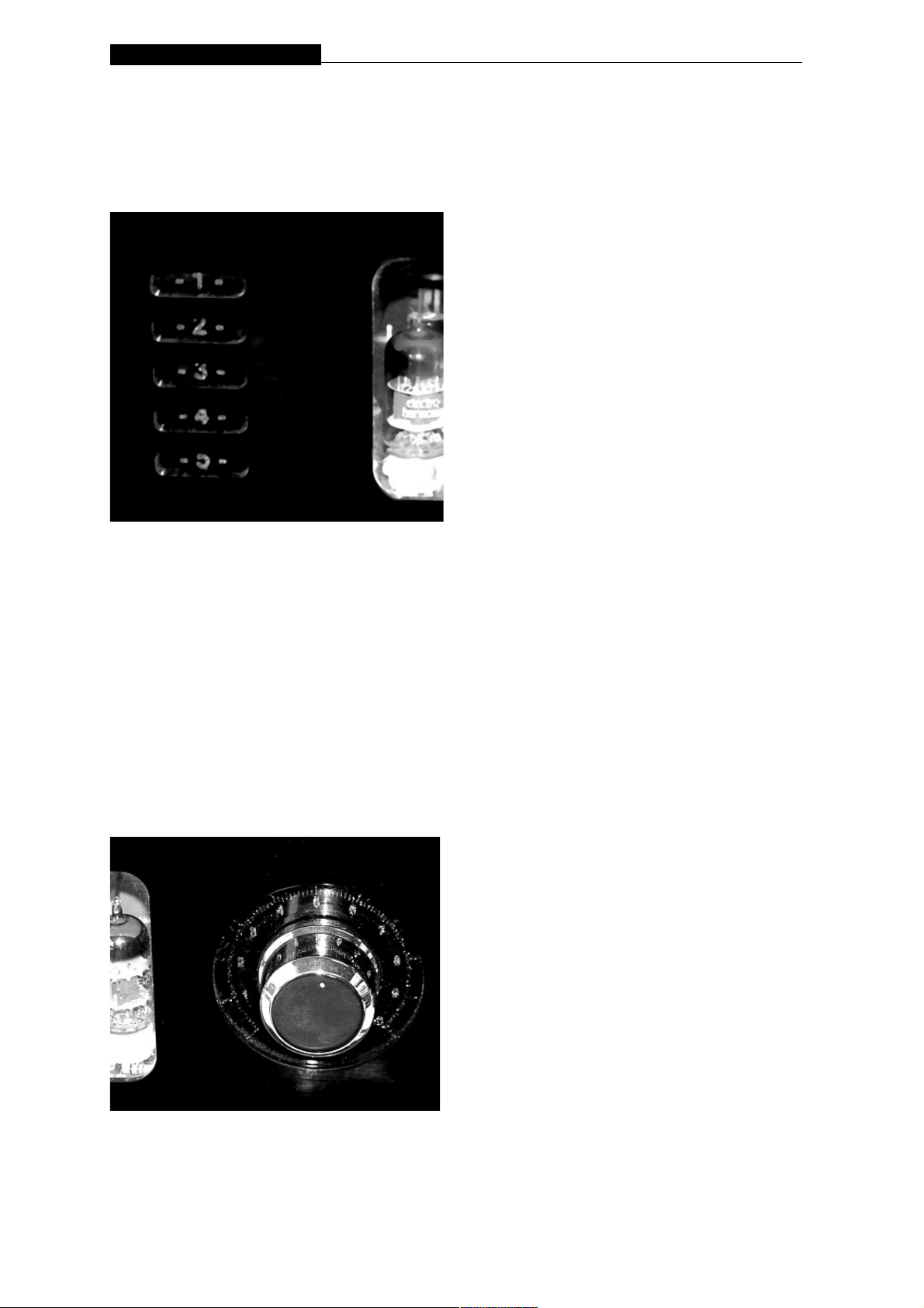
The front panel of the Assistent 50 is spitted in 3 sections:
On the left side is the display for the 5 input sources.
The chosen input is indicated by a blue light.
When the Assistent 50 is in the Mute function, this input sources is flashing.
In Stand By mode all input sources are dark.
The middle of the front is showing the Audio Valve Logo, and is displaying in a
blue light a.s.a. the Assistent 50 is switched on with the remote control - the
button ON/OFF.
Page 5
Assistent 50 integrated tube amplifier_____________________
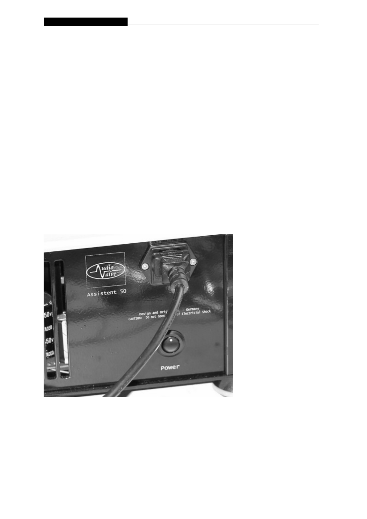
The volume potentiometer with the heavy knob is the third section on the right
side.
Also this section is displaying in a blue light while in operate mode.
The volume is remote controlled, but has also the possibility of manual use.
By the use of the remote control the scala illumination is getting darker
while the motor potentiometer is turning.
REAR PANEL
MAIN VOLTAGE and Main Power SWITCH
The heavy duty rocker switch is on the rear side under the main plug and
switches the mains power of the amplifier ON / OFF.
When switching on the Assistent 50 the front logo in the middle of the plexiglass
illuminates in red light.
This signal that the Assistent 50 is under main voltage, but not in the operate
mode.
This has to be done with the remote control.
Be sure that you understand the requirements fully
before you make any connection to this amplifier.
Page 6
Assistent 50 integrated tube amplifier_____________________
INPUT TERMINALS
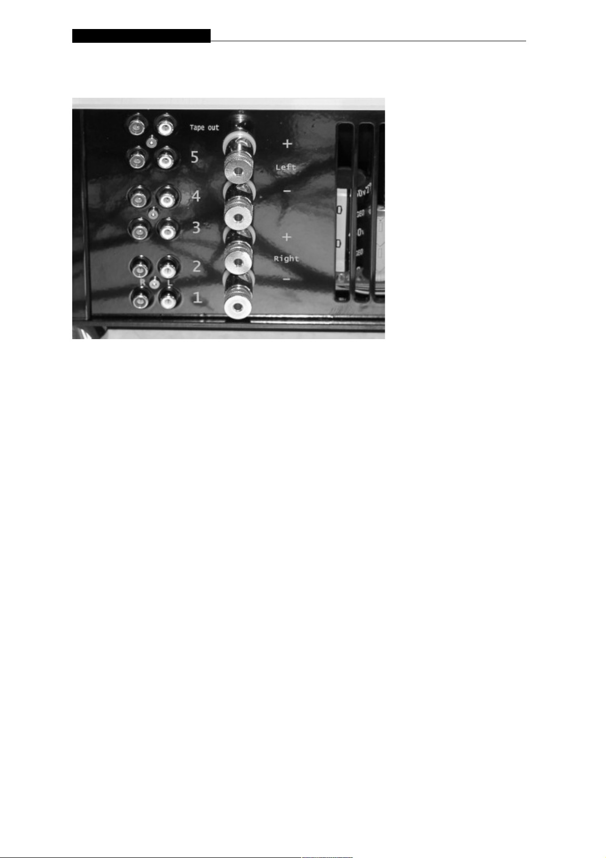
The 5 RCA INPUTs are standard RCA terminals for the
use of unbalanced input signals coming from most signal sources .
SPEAKER TERMINALS
Speaker terminals - 8 Ohm - are located on the left rear panal, close to the input
sources.
Two pairs of heavy duty gold plated binding posts for each cannel are supplied.
CONNECT your loudspeaker positive terminal to the
amplifier (+) output terminal. Connect your loudspeaker
negative terminal to the ( - ) output terminal.
POLARITY - PHASING
Quality of the connections must be examined to ensure a high
performance trouble free operation is enjoyed. Check that the connections are
tight, but do not overtighten with exessive use of spanners etc. If bare wires are
used, make sure that no loose strands of wire short across to the other
terminals or the amplifier chassis. When using plugs such as Banana, be sure to
use good quality one`s with a firm fit.
Please remember that the AUDIOVALVE Assistent 50
amplifier is a high quality electronic instrument
capable of an exeptional level of performence.
Page 7

Assistent 50 integrated tube amplifier_____________________
INSTALLATION AND OPERATION
MAINS VOLTAGE
CHECK that the mains voltage printed on the rear of this
amplifier is similar to the mains voltage normaly supplied to
your area. If indoupt, please consult your AUDIOVALVE dealer.
Please notice that you never exceed the mains voltage in the prescribed value
shown at the lable of the serial number on the rear side. If you can`t provide the
amplifier with the exact shown main voltage, please use a voltage stabilizer
- particulare for the US
and Mainland China marcet.
The main fuse housing in the case from main plug on the reas side. Use fro 230
VAC the type 1,5 amp-sb and for 115 AVC the type 3,15 amp-sb.
PLACEMENT AND VENTILATION
This AudioValve ASSISTENT 50 amplifier is designed to
operate at a moderately high temperature. The ideal location
is on the rigid stand or floor mounted away from direct contact with any objects,
materials or deep pile carpets which may be effected by the heat or which may
interrupt the flow of air around the amplifier.
When operating the amplifiers quite a lot of heat is generated which should be
allowed to dissipate without restriction. Make sure that no objects are placed on
the top of the amplifier. Always ensure adequate ventilations.
MAIN POWER connection is via supplied plug-in lead. The standard IEC socket
connects the mains power at the amplifier end while a local mains plug is
required at the wall end. In the event where a "local" plug needs to be fitted to
the wall end of the lead, ensure the at the plugs is wired correctly by a suitable
qualified or experienced person.
Ensure the main switch of the rear side of this amplifier is OFF before attempting
any modification of the mains connection.
MAINS FUSE
A Mains fuse is fitted within the IEC Mains / Line socket on the rear of the
amplifier. A small draw at the bottom of this socket may be removed (after the
IEC plug is removed) by levering it out with a flat blade screw driver. The fuse
fitted should be razed at no greater than 1,6A for 230 VAC and 3,15A for 115
VAC slow blow.
In the unusual event that this fuse should blow, you must first
establish the cause of this failure, cure the fault and then replace the fuse with
one of the same type.
DO NOT FIT A FUSE WITH HIGHER RATING.
Page 8

Assistent 50 integrated tube amplifier_____________________
"Start your engine ... "
Connect the amp to the main source.
The display in the front is dark.
Then you switch the main switch on the back panel, the display will turn red.
Then you press the on/off button on the remote for a short moment, just one
time, don`t hold it long, the red display will go off and beginn slightly to shinning
blue. Then you waite for about a periode of 1 min. the tube is heating in the
meantime will come up and the display will very slowly gets blue shining.
After 1 min. the plate voltage is loaded, the display blue shining completely and
the amp is out of the mute phase.
If you press ANY button during this peride, the amp and you are" confuse " it will
not start up.
AUTOMATIC BIAS CONTROL FUNCTION ( ABR )
Every QQE 03/12 power tube is controlled by an unique complete automatic bias
regulator for each system in the tube.
When the amplifier is warmed up, the red ABR - led next to each power tube will
light up, more or less bright shining in colour.
Page 9

Assistent 50 integrated tube amplifier_____________________
SPECIFICATIONS:
Type: Integrated stereo class - A tube amplifier
Power consumption: 220 VA in "progress - mode",
8 watt in "remote-mode",
80 watt in "stand-by" mode
Power: 2 x 50 watt / 8 ohm
Inputs: 1 - 5; outputs: 1 rec - out
Efficency: 0 dbm
Damping: 8
Input impedance: 47 kOhm
Harmonic distortion: < 0,3% / 20 watt%
s/n ratio: - 86 dbm
gain: 25 db
Bandwide: 15 hz - 70 khz
Dimensions: W 420 x H 155x D 320 mm
Weight: 18 kg
Functions: all be remote control
Origin: Germany
tubes: 2 pcs. ECC82, 2 pcs. ECC 83, 8 pcs. QQE 03/12, RS 1029 or CV 2798
Page 10

Assistent 50 integrated tube amplifier_____________________
W A R R A N T Y
AUDIOVALVE warrants its components for a two - year period on all electronics
and a 90-day period on the tubes from the purchase date.
In the event of a failure of your amplifier , AUDIOVALVE will repair or readjust
this unit or , should the occasion arise , will replace it provided that all conditions
stipulated in this warranty are met.
In order to initiate service of any kind it is necessary to obtain distributor or
dealer authorization prior to shipping the unit for service.
Any of the following conditions shall void the warranty:
• Operation not in accordance with this manual.
• Abuse , accidental damage or unauthorized modifications , as determined
by AUDIOVALVE or its agents exclusively.
• Removal , defacing or falsifying of the serial numbers.
• Shipping without the original complete factory crates.
Page 11

Assistent 50 integrated tube amplifier_____________________
WARRANTY REGISTRATION
Please fill out and return this warranty form to the distributor within 15
days of the purchase date with this form here, or make it online on our
webside.
• MODEL : _______________________________________________
• SERIAL NUMBER : _______________________________________
• PURCHASE DATE : ______________________________________
• AUTHORIZED AUDIOVALVE DEALER:
• PURCHASER`S NAME : ___________________________________
• STREET ADDRESS : ______________________________________
• CITY : __________________________________________________
ZIP / POSTAL CODE : _____________________________________
Page 12
Assistent 50 integrated tube amplifier_____________________
 Loading...