

Page 1

Page 2
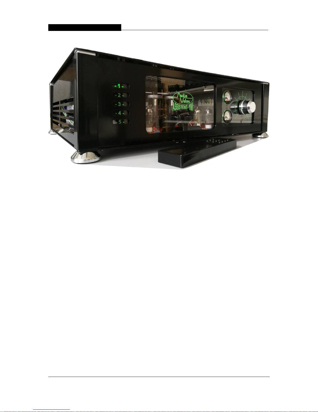
Assistent 100 – Mark 2 integrated tube amplifier_ ___________
ASSISTENT 100 - Mark 2
Integrated stereo triode tube amplifier
owner manual
This handcrafted product was special made for your high demands,
to display the music in its finest way.
We guarantee, that this amplifier was carefully produced
and tested in all details.
Page 3

Assistent 100 – Mark 2 integrated tube amplifier_ ___________
Congratulations on your decision to become the proud owner of the
AUDIO-VALVE Prometheus power amplifier.
This manual has been prepared to help you understand the operation
of your amplifier and to provide some information about its design and
the variety of ways it may be used.
We have designed and manufactured this amplifier to faithfully and
accurately reproduce music. This hand build instrument should give
a lifetime of pleasure and with a little care and a full understanding
of the operation recommendation in this manual the Prometheus
should provide trouble free performance.
List of contents
- Warning and precautions
- Front panel - rear panel
- Drawing front panel
- Drawing rear panel
- Input - output terminals
- Polarity - phasing
- Installation and operation
- Automatic bias control ( ABR )
- Specifications
Please take time to read this manual
thoroughly before using your amplifier
Page 4

Assistent 100 – Mark 2 integrated tube amplifier_ ___________
WARNING
This amplifier Prometheus operates in class - A and is
therefore capable of generating a moderately high temperatue
which requires careful placing to aviod any effect this heat
may have on other equipment, furniture and fittings etc.
Do not remove the top cover from this ampllifier.
Hazardous voltages are present. Any repair work should
be referered to a suitable qualified and experienced
service person.
Do not attempt to connect any input of this amplifier to
any of its outputs.
Do not earth any output terminal or connect any of these
terminals together without following the instructions in
this manual or seeking qualified assistance.
Do not place this amplifier in any position where liquids
or any foreign material may accidentally enter it.
Do not disconnect any in / output wire, while the amplifier is
operating.
Do not connect any voltage source short circut, earth / ground
or appliance (other than suitable HiFi quality loudspeakers )
to any output terminal.
Some preamplifiers, proccesors, CD players etc produce
large switching pulses when switched on, causing a loud
click through the loudspeakers. For this reason, turn on
all other equipment in your system and operate the
Stand - by mode of the amplifier before turning on the Prometheus.
No forget is procedure: power amplifiers all time: first OUT and
last ON.
Page 5

Assistent 100 – Mark 2 integrated tube amplifier_ ___________
Introduction to AudioValve
All AudioValve products are designed by Helmut Becker and feature
advanced, modern circuitry, combined with the superb sound of
valves. Now it is no longer necessary to sacrifice one to get the other.
Combining the finest in modern valve technology with sophisticated smartbias
circuitry, AudioValve brings you the best of both worlds - and more.
With contemporarily-styled chassis built from 4 & 5 mm laser-cut steel, every
amplifier and pre-amplifier we manufacture utilises double sided PC boards
and automatic bias regulators to ensure a continuously uniform current flow
to and a perfect match between all the valves throughout their entire life,
even as the various valves decay at different rates.
Unlike other valve amplifiers, where a certain amount of guesswork and
experience is required to know when valves need to be replaced, with
AudioValve amplifiers not only do valves not have to be removed
prematurely (prior to burn out), but when burnt out does occur, only the bad
valves need to be replaced. The amplifier will automatically adjust and
distribute the total current flow to optimally match the new configuration.
AudioValve amplifiers always deliver nothing but the most advanced,
economical, high quality valve sound. Power output valves in most models
may be varied among several different types with no modifications to the
units, so that an appreciable degree of sonic system matching and user
preference may be accommodated.
No matter what combination of valves one uses (differing valves, new valves, old valves),
one will experience at all times the balanced and coherent sound of amplifiers working
with brand new, perfectly matched valves. The bonus is that there is never any need to
use a meter or screwdriver to adjust bias on any valve in any condition of
operation. AudioValve�s smart - bias circuitry is the best and most
unobtrusive available!
The ASSISTANT 100 amplifier represents exceptional value for money. We
have designed and manufactured this power amplifier to faithfully and
accurately reproduce music. The high quality of components used and
advanced valve operational principles employed in this design ensures that
you will enjoy the superb audio performance and pride of ownership,
inherent in such a hand-crafted product as this, for many years to come.
BIAS AND PCB
Traditionally, valve biasing is performed with a screwdriver to adjust the bias
current to the valve. Any such adjustment can only be optimum for an
instant as valves, even selected ones or a matched set, cannot hold a
consistency of performance in the long term. Each valve will deteriorate
individually and, if in a set, not necessarily in the same way as others in that
set. A matched pair or quad will therefore only remain matched for a
relatively short period of time!
Helmut Becker of AudioValve has developed a unique valve biasing circuit
that automatically monitors, biases and controls each valve independently
thereby maintaining any number of valves at their optimum performance
level. These valves do not even have to be of the same type or condition.
This is AudioValve�s Automatic Bias Regulator (ABR) circuit, a feature that
Page 6

Assistent 100 – Mark 2 integrated tube amplifier_ ___________
AudioValve considers essential to deliver optimum performance from any
multiple power valve amplifier and, in particular, to get the very best from
the stunning 6C33.
AudioValve�s ABR therefore delivers a long awaited dream - to combine
the operational convenience of solid-state amplifiers with the sonic benefits
of pure triodes. True 21st century valve-technology!
The PCB
All electronic components of the ASSISTANT 100 are mounted on one double
sided mil-spec printed circuit board created from a pure copper covered
panel using CAD/CAM software to produce a circuit board completely free
from solder bridges or point-to-point wiring. All signal and power tracks are
separated by grounding tracks to minimise cross-talk and noise and the
overall construction is designed to ensure low microphony and excellent
conductivity.
The advantage of this approach is a consistency and reliability of
performance and the certainty that all production examples of any
AudioValve model will be exactly like its reference sample! This is in stark
contrast to amplifiers that employ hardwired components, where the sonic
outcome will depend upon the construction technicians ability to solder all
joints to a consistent standard and place the components in the same
position and orientation as those of the reference sample to ensure
consistency of interaction with other components.
AudioValves PCB ensures that all components receive the same accuracy
of assembly and that electro-dynamic interactions between components
are constant in all aspects of the construction. Only the use of a well thought
out and calculated printed circuit can achieve this.
MORE WARNINGS & PRECAUTIONS
The ASSISTANT 100 amplifier operates in a floating class-A and is therefore capable of
generating moderate to high temperatures. This may have an adverse
effect on other equipment, furniture and fittings close by and you will need
to position the amplifier carefully to avoid this.
Do not remove the top cover or the metal top from this amplifier whilst it is in
operation or connected to the mains supply as you will be exposed to
potentially lethal voltages.
Do not attempt to connect any input of this amplifier to any of its outputs
otherwise damage to components will result.
Do not earth any output terminal or connect any of these terminals together
without following the instructions in this manual or seeking qualified
assistance.
Do not connect any voltage source, short circuit, earth/ground or appliance
(other than a suitable Hi-Fi quality loudspeaker) to any output terminal.
Repair work should only be undertaken by a suitably qualified service
engineer.
Be sure that you understand the requirements fully
before you make any connection to this amplifier or switch ON !!
This amplifier ASSISTENT 100 operates in class - A and is
Page 7

Assistent 100 – Mark 2 integrated tube amplifier_ ___________
therefore capable of generating a moderately high temperature which requires care full
placing to aviod any effect this heat may have on other equipment, furniture and fittings
etc.
Do not remove the top cover from this amplifier.
Hazardous voltages are present. Any repair work should
be refer to a suitable qualified and experienced
service person.
Do not attempt to connect any input of this amplifier to
any of its outputs.
Do not earth any output terminal or connect any of these
terminals together without following the instructions in
this manual or seeking qualified assistance.
Do not place this amplifier in any position where liquids
or any foreign material may accidentally enter it.
Do not disconnect any in / output wire, the power cord or the connecting cables between
the amp and the power supply , while the amplifier is operating.
Some preamplifiers, processor, CD players etc produce
large switching pulses when switched on or off, causing a loud
click through the loudspeakers. For this reason, turn off your power amplifier at first
when you plan to switch off your audio device.
Turn on your power amplifier at last when you plan to switch on your audio
device.
All handling at the open amplifier has to be done
when the main power plug is disconnected .
Please notice that you never exceed the mains voltage in the prescribed value shown at
the lable of the serial number on the rear side. If you can`t provide the amplifier with the
exact shown main voltage, please use a voltage stabilizer - particulare for the US ( 115
VAC ) market and Mainland China
The amplifier needs a certain time to form the brand new components (capacitors)
otherwise they can be destroyed.
Use the Stand - By mode for warm hold periodes ( tube heating ) when you aren`t
listening. Please switch OFF the amp while leaving the house or sleeping !
Please only do use your amplifier while listening to music.
Page 8

Assistent 100 – Mark 2 integrated tube amplifier_ ___________
UNPACKING & SET UP
Ideally your dealer will carry out this process for you. If you wish to unpack
and set-up the amp yourself please follow the following steps carefully.
Each ASSISTANT 100 comes in its own wooden crate and weighs 40kg
unpacked, so it is advisable to have another person assist you with the
following un-packing operations.
First remove the lid to the crate using a pozi-drive No 2 screwdriver.
The power output valves are packed individually inside the crate. Remove all
four of these and place them somewhere safe!
To remove the ASSISTANT 100 from its crate first undo the plastic wrapping. Each
person should then grab the outer rim of the Perspex top and lift the amplifier
until it can be rested on the edge of the crate. Any further lifting should be
carried out holding the bottom of the amplifier chassis. Do not lift the
amplifier using the protective grille!
We suggest you leave all packaging in the crate and re-fix the top so you
can use it again in the unlikely event that you need to return the unit under
warranty (see warranty conditions at the end of the manual) or place the
unit in storage.
Next remove the protective metal top plate and Perspex top plate assembly from the
top of the amp so you can fit the power valves. This cover is fixed to the
Perspex top plate by screws. This top plate is fixed to the amp by 4 round
smooth topped bolts, one in each corner of the top plate. To remove the
assembly, undo these bolts, not the screws.
It is possible that the driver valves already on the circuit board may have
been vibrated loose in transit, so first check that they are securely in place – if not,
push them firmly home. Once you have done this, remove the power
valves from their packing one at a time and fit them into the vacant sockets.
Take care to align the pins correctly before pushing them fully into position
otherwise the socket may be damaged requiring a return of the unit to the
factory for repair.
Once all four power valves have been installed, clean any finger marks off
them and the driver valves with a tissue or lint-free cloth and replace the top
plate assembly. This assembly is decoupled from the amplifier�s chassis by
plastic washers. When you re-fit the cover do not over-tighten the knurled
nuts or the decoupling will be reduced. It is sufficient to tighten the nuts until
they touch the top plate and then tighten one half-turn more only.
The amplifier is now ready for connecting into your audio system. Experience
has shown that these amplifiers benefit from resting on a solid surface rather
than carpet. Your AudioValve dealer will be able to recommend a suitable
support that ensures adequate airflow around and through the amplifier. Do
not place this amplifier in a position where liquids or any hard objects may
accidentally enter it.
HAVE A LOOK THAT ALL TUBE CORRECT PLACED IN THE TUBE
SOCKETS BEFORE YOU SWITCH ON THE AMP !!
Page 9
Assistent 100 – Mark 2 integrated tube amplifier_ ___________
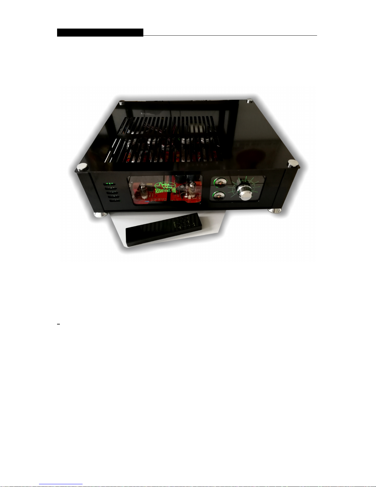
FRONT PANEL
The ASSISTENT 100 is remote controlled designed, this includes also the volume control,
input selection, stand-by mode, mute, and power ON or OFF.
The front panel of the ASSISTENT 100 is spitted in 3 sections :
On the left side is located the 5 channel input selection, shown by a blue shinning LED.
On the right you see the VOLUME pot and 2 relative level meters.
In the middle is a clear acryl window which shows the blue shining AudioValve logo when
the amp is in operate mode, and a red one, when the amp is in the sleep mode (power –
off ). The blue brightness is internal adjustable.
On the right side of the ASSISTENT 100 is located the volume potentiometer,
( which is also adjustable by hand with a heavy knob ) and two relative power meters
with integrated back ground light, which will be shinning by higher out level.
The 2 section ALPS motor potentiometer guaranteed a high accurate analog volume
control . The heavy knob is surrounded by a blue shinning scale while in operate mode.
Page 10
Assistent 100 – Mark 2 integrated tube amplifier_ ___________
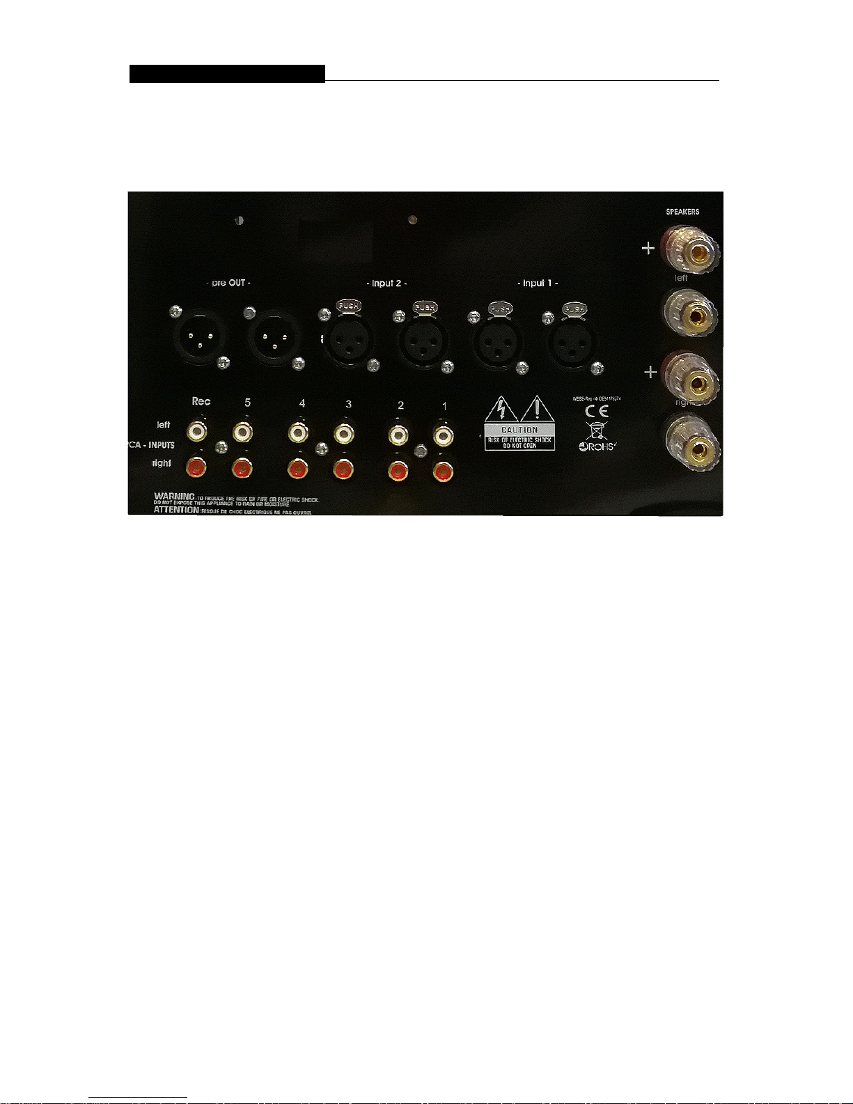
REAR PANEL
all possibilities to connect your amp …
INPUT TERMINALS
The 5 pair RCA and 2 pairs XLR Inputs are standard terminals for the
use of unbalanced and balanced input signals coming from the signal sources . The
ASSISTENT 100 uses for all fage XLR inputs female jackets and for the TAPE output one
pair of RCA jackets.
OUTPUT TERMINALS
The ASSISTENT 100 Mark 2 has two pair of output terminals in vertical direction for 8
ohm loads, you can internal switch to 4 ohm speakers
PLACEMENT AND VENTILATION
This AudioValve ASSISTENT 100 amplifier is designed to
operate at a moderately high temperature. The ideal location
is on the rigid stand or floor mounted away from direct contact with any objects,
materials or deep pile carpets which may be effected by the heat or which may interrupt
the flow of air around the amplifier.
When operating the amplifiers quite a lot of heat is generated which should be allowed to
dissipate without restriction. Make sure that no objects are placed on the top of the
amplifier. Always ensure adequate ventilations.
Page 11

Assistent 100 – Mark 2 integrated tube amplifier_ ___________
INSTALLATION AND OPERATION
MAIN VOLTAGE
and Main Power Plug ( fuse ) and Main Switch
MAIN POWER connection is via supplied plug-in lead. The standard IEC socket connects
the mains power at the amplifier end while a local mains plug is required at the wall end.
In the event where a "local" plug needs to be fitted to the wall end of the lead, ensure
that the plugs is wired correctly by a suitable qualified or experienced person.
Ensure the amplifier is disconnected from the main voltage before attempting
any modification of the main connection.
The heavy round duty rocker switch for the main voltage ON /OFF is located on the rear
side of the power supply near by the main power connector. The main fuse is next to the
main plug, the value is 3,15 amp sb. for 230V AC or 6 amp. sb as for 117V AC.
DO DISCONNTECT the main power cord from the voltage when you check the fuse !
When the ASSISTENT 100 is switched ON with the the power switch, the display in front
of the amplifier shows the AUDIO VALVE logo in a sleep mode, and the display of the
main power supply is NOT shinning, but the lights in the panel meter glow. So you konw,
the MIAN switch is in poper ON mode. This status shows that the ASSISTENT 100 is
prepared for main power function.
Now you can switch ON the amp by the remote control, press the the power button ON
and you see the front panel will be red shining by LED lights – its the STAND BY mode
too. After a wile from 30 seconds the amp go in the operate mode, the anode plates
become high voltage and the front panel light chance from red to blue or green. Now the
amp ready to play music.
Please switch OFF the main power while leaving the house or sleeping, the red light in
front will be go off !
Make sure that your home voltage is the same as the printed voltage on the lable of the
rear side of the power supply.
Please notice that you never exceed the main voltage in the prescribed value shown on
the lable of the serial number on the rear side.
If you can`t provide the amplifier with the exact shown main voltage, please use
a voltage stabilizer - particulare for the US or Taiwan ( 115 VAC, max. 120 V AC )
and Mainland China market with 230 V AC.
MAIN FUSE
The Mains fuse is fitted in the IEC Main / Line socket on the rear of the power supply.
The fuse must has the value 3,15A for 230 VAC and 6 A for 117 VAC slow blow.
If the fuse keeps blowing up the amplifier must be checked by a professionel technican.
DO NEVER FIT A FUSE WITH HIGHER RATING.
Page 12

Assistent 100 – Mark 2 integrated tube amplifier_ ___________
REMOTE CONTROL
In case the remote doesn`t work or you replace the battery, please follow the
instructions:
- Make sure that the batteries are fitting tight at their place.
- On the back side of the remote through a little hole you can see a blue LED .Located on the PC
board of the remote.
- Now press at the same time the volume up and down button together, untill the LED flashes, then
stop doing so.
- If it flashes 1 time, the remote is for the CONDUCTOR
- 2 times for the EKLIPSE
- and 3 times for the ASSISTENT 50 and 100 .
- You can change the program of the remote by pressing the buttons of the volume, untill the LED
is flashing as much as you need to be the correct program.
Page 13

Assistent 100 – Mark 2 integrated tube amplifier_ ___________
CHANGING VALVES AND POWER VALVES
IMPORTANT before changing a valve you must remove the mains lead from
the IEC socket and allow the valves to cool down. Touching a hot valve can
cause very serious burns.
Standard power valve type: GU50
.
Automatic Bias Regulator (ABR ) function and interpretation
Each power valve is controlled by an ABR for each circuit within the
Valve.
There are two LEDs right side each power valve circuit. These LED`s
indicate the status of the valve when the amplifier is in OPERATE
mode and will light if the valve malfunctions in some way or in STAND – BY mode.
If a power valve in the ASSISTANT 100 falls in performance to the point
where it needs to be changed, the appropriate ABR circuit will
indicate this by lighting LEDs next to the valve that needs
replacing.
Please note: In the “STAND BY” mode the ABR red LED shinning too !!!
Exchange the faulty valve for a suitable replacement from the list
above. You need only exchange the faulty valve as the ABR
automatically adjusts the interrelationship between the valves to give
optimum sound.
AudioValve will supply individual replacement valves (or complete
sets of valves) through its distributors at an extremely competitive
price.
Once you have changed the faulty power valve the LEDs should go
out. If this or any other of the LEDs remains lit, turn the amp off at the
POWER switch and contact your AudioValve dealer. Under normal
operating conditions none of the LEDs are lit, athough:
if the amplifier is in STAND BY mode, a LED on each power valvel
light up, and when the amplifier is being driven to very high output
levels it is normal for the LEDs that monitor the
valve circuits to simultaneously light dimly.
Page 14

Assistent 100 – Mark 2 integrated tube amplifier_ ___________
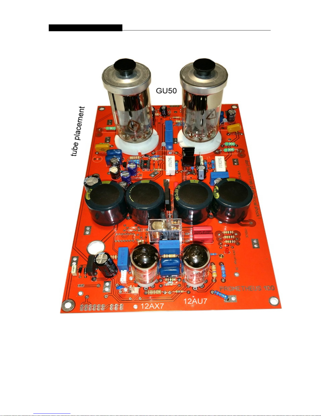
TUBE PLACING
the 4 big valves are russia models named GU50 – and you no can replace them by an
other models.
SPECIFICATIONS
Inputs: 5 pair RCA – 47Kohm, 2 pair fage XLR ( Input 1+2 )
Outputs: one pair RCA TAPE OUT, 2 pairs 8 ohm speaker terminals
Efficiency: 0dBm for max. power output
power consumption: 300 - 800 VA max., stand - by mode: 30VA
power output: 100 watt rms before start clipping / 80 watt 1% dist. / 8 ohm load, per
channel
distortion – 8 ohm load
80 watt - 0,15 %
100 watt – start clipping
bandwide: - 3db / 5 hz up to 40 khz
damping: 20
s/n - ratio: better 80 db
full automatic bias controlled power tubes
tubes: 2 x 12AX7, 2 x 12AU7, 4 x GU50
Dimensions & weight: 54cm lenght * 45cm wide * 17cm high, 40 kg
NOTE:
we use 2 output transformers size for 500 watt each channel, this make a incredible bass and
control.
Page 15

Assistent 100 – Mark 2 integrated tube amplifier_ ___________
W A R R A N T Y - Terms
AUDIOVALVE warrants its components for a three-year period on all
electronics and a 90-day period on the tubes from the purchase date.
In the event of a failure of your amplifier , AUDIOVALVE will repair or
readjust this unit or , should the occasion arise , will replace it provided that all
conditions stipulated in this warranty are met.
In order to initiate service of any kind it is necessary to obtain distributor or
dealer authorization prior to shipping the unit for service.
Any of the following conditions shall void the warranty:
Operation not in accordance with this manual.
Abuse , accidental damage or unauthorized modifications , as determined by
AUDIO VALVE or its agents exclusively.
Removal , defacing or falsifying of tne serial numbers.
Shipping without the original complete factory crates.
Page 16

Assistent 100 – Mark 2 integrated tube amplifier_ ___________
WARRANTY REGISTRATION
Please fill out and return this warranty form to the US distributor within 15 days of the
purchase date or use our online warranty register form by: www.audiovalve.de
MODEL : _______________________________________________
SERIAL NUMBER : _______________________________________
PURCHASE DATE : ______________________________________
AUTHORIZED AUDIO - VALVE DEALER:
PURCHASER`S NAME : ___________________________________
STREET ADDRESS : ______________________________________
CITY : __________________________________________________
ZIP / POSTAL CODE : _____________________________________
Send to :
AudioValve
Mr. Becker
Dormannweg 48 B
34123 KASSEL - Germany
[email protected]
Page 17

Assistent 100 – Mark 2 integrated tube amplifier_ ___________
CE – Confirmity
Declaration Of Conformity
declare under our sole responsibility that the product(s)
Manufacturer: AudioValve,
Germany, 34123 KASSEL, Umbachsweg 70, [email protected]
to which this declaration relates is/are in conformi y with the requirements of
the following directive(s)
Product Name: Asistent 100 Mark 2 – power mono blocks
Product Type: Audio Amplifier
Complies with Standards:
LVD: 92/31/EEC, 93/68/EEC, & 73/23/EWG
Safety: EN60065
EMC: EN55013, EN55020, EN55022, EN55103, EN61000-3-2, & EN61000-3-3
Page 18
Assistent 100 – Mark 2 integrated tube amplifier_ ___________
 Loading...